








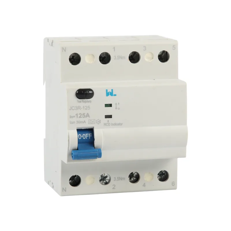
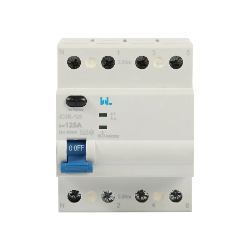
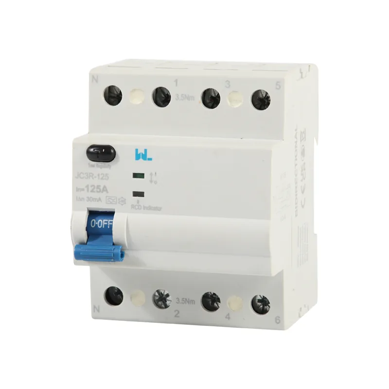
Dispositivo de corriente residual JC3R-125
Introducción
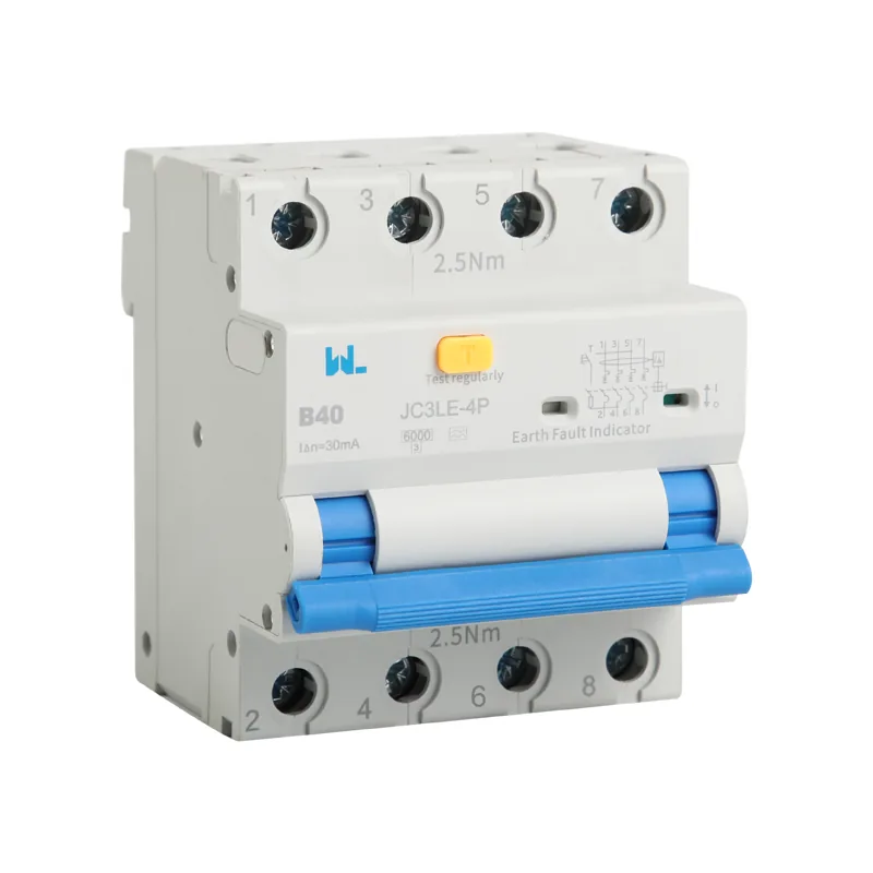
JC3R-125 4 pole RCDs may be used to provide earth fault protection on 3 phase, 3 wire systems, as the current balance mechanism does not require a neutral to be connected in order to operate effectively.
JC3R-125 RCDs must never be used as the sole method of direct contact protection, but are invaluable in providing supplementary protection in high risk environments where damage may occur.
However W9 GROUP JC3R-125 4 pole RCDs do, ideally, require a neutral conductor to be provided on the supply side of the RCD in order to ensure that the test circuit operates satisfactorily. Where connection of a neutral supply is not possible, then an alternative method of ensuring that the test button is operational is to fit a suitably rated resistor between the load side neutral pole and a phase pole not associated with the normal test button operation.
JC3R-125 4 pole RCD is available in ac type and A type. AC type RCDs are only sensitive to sinusoidal type fault currents. A type RCDs, on the other hand, are sensitive to both sinusoidal currents and “unidirectional pulsed” currents, which may be present, for example, in systems with electronic devices for rectifying the current. These devices are capable of generating pulsed shape fault currents with continuous components that an AC type RCD is unable to recognize
JC3R-125 RCD provides protection against earth faults occurring in equipment and reduces the effects of electric shock on human beings and thus saves lives.
JC3R-125 RCD measures the current flowing in the live and neutral cables and if there is an imbalance, that is current flowing to earth above the RCD sensitivity, the RCD will trip and cut off the supply.
JC3R-125 RCDs incorporate a filtering device to provide protection against transient surges in the supply to the unit, thus reducing the occurrence of unwanted tripping
Information
| Estándar | IEC61008-1, EN61008-1 | |
| Electronic features | Corriente nominal en A (A) | 25, 40, 50, 63, 80, 100, 125 |
| Tipo | Electromagnetic | |
| Type(wave form of the leakage sensed) | AC, A, AC-G, A-G AC-S and A-S are available | |
| Polacos | 3P+N | |
| Tensión nominal Ue (V) | 3P+N: 400/415 | |
| Sensibilidad nominal IΔn | 30mA, 100mA, 300mA are available | |
| Tensión de aislamiento Ui (V) | 500 | |
| Rated residual making and breaking capacity IΔm | 500(In=25/40A), 630(In=63A), 1000(In=80/100A) | |
| Frecuencia nominal | 50/60Hz | |
| Capacidad de ruptura nominal | 6KA, 10KA | |
| Tensión de resistencia a la impulsión nominal (1,2/50) Uimp (V) | 6,000 | |
| Voltaje de prueba dieléctrica a la frecuencia indicada durante 1 minuto (KV) | 2.5 | |
| Nivel de contaminación | 2 | |
| Características mecánicas | Vida eléctrica | 2,000 |
| Vida mecánica | 4,000 | |
| Indicador de posición de contacto | Sí | |
| Nivel de protección | IP20 | |
| Temperatura de referencia para el ajuste del elemento térmico (℃) | 30 | |
| Temperatura ambiente (con promedio diario ≤35℃) | -5…+40 | |
| Temperatura de almacenamiento (℃) | -25…+70 | |
| Instalación | Tipo de conexión de terminal | Cable/tablero tipo U/tablero tipo pin |
| Dimensiones del terminal superior/inferior para el cable | 25 mm2/18-3 AWG | |
| Dimensiones terminales superiores/inferiores para la barra de bus | 10 mm2/18-8 AWG | |
| Torque de ajuste | 2,5 N*m/22 In-lbs | |
| Instalación | En el soporte de pared según la norma DIN EN 60715 (35 mm) | |
| Conexión | Están disponibles desde arriba o desde abajo |