








Thermal-Magnetic vs Electronic Trip Breakers
Two quotations can offer the same breaker current and still describe very different protection. One may provide a simple overload and magnetic release; the other may offer several adjustable delays and additional functions. Buying the more elaborate option without a settings plan can add work without solving the feeder’s actual problem.
Quick answer: the thermal magnetic vs electronic trip decision depends on the required protection functions, coordination and operating support. A thermal-magnetic release can suit a documented feeder duty with relatively simple adjustment. An electronic release can provide more flexible protection, but the fitted version determines what is available. Neither release type establishes breaking capacity, product certification or selectivity by itself. Compare the two candidates at the same voltage, fault duty and load conditions, then include the cost of commissioning and maintaining their settings.
What changes when the trip unit is electronic
A thermal-magnetic release derives overload operation from heating and high-current pickup from magnetic actuation. An electronic trip unit measures current, evaluates its protection settings and commands the breaker mechanism to open. In both cases, the complete circuit breaker must interrupt the fault within its declared ratings.
Electronic units may offer long-time, short-time, instantaneous or ground-fault overcurrent functions. The familiar letters L, S, I and G describe those functions when provided. They are not a guarantee that every electronic MCCB includes all four, and ground-fault overcurrent protection is not automatically equivalent to an RCD intended for additional personal protection.
Adjustment can also exist in a thermal-magnetic release. The available overload and magnetic settings depend on the variant. A useful comparison therefore starts with the fitted function list, not a blanket statement that mechanical means fixed and electronic means adjustable. Review the basic thermal and magnetic trip principles before comparing setting schedules.
Compare trip curves under the same conditions
An electronic release may offer a more controllable response over a declared range, but a claim of better accuracy needs actual tolerance data. Compare the stated pickup tolerance, operating-time band, current reference, temperature conditions and frequency. A brochure adjective such as precise is not a replacement for these values.
For example, an overload setting expressed as a multiple of sensor rating is not necessarily the same as one expressed as a multiple of frame current. This is a calculation issue before it becomes a performance issue. In an illustrative calculation, 0.8 times a 250 A reference gives 200 A. The result is meaningful only after the manufacturer’s reference and permitted range are established.
Do not convert that arithmetic into a claim that either candidate trips immediately at 200 A. Each release operates according to its curve and defined conditions. A comparison that omits the curve band can make two devices appear equivalent when their responses to starting current or a sustained overload differ.
| Selection factor | Thermal-magnetic release | Electronic release |
|---|---|---|
| Overload response | Thermal operating characteristic | Electronic long-time function when provided |
| High-current response | Magnetic pickup characteristic | Instantaneous or other documented functions |
| Adjustment | Fixed or adjustable by variant | Function and range depend on the trip unit |
| Diagnostics | Depends on accessories and indication | May be available; verify the actual version |
| Communications | Not implied by release type | Not implied by the electronic designation |
| Breaking capacity | Check the complete breaker at voltage | Check the complete breaker at voltage |
Choose coordination functions the project can use
Protection coordination is an arrangement-level result. An adjustable short-time delay may help an upstream device allow a downstream protective device to clear a fault, but the permissible delay also depends on equipment withstand and the fault study. Simply making the upstream device slower can create a different problem.
Use manufacturer coordination information for the exact device pair, operating voltage and settings. Time-current curves are useful in the overload and delayed regions; high-current interaction may require tested selectivity or backup data. Do not transfer a tested result between brands, frame sizes or release variants without supporting evidence.
The operating team also needs to maintain the selection. Who owns the approved settings? Can an unauthorised adjustment be detected? Will the records survive a breaker replacement? More adjustable functions create more options and more configuration to control. For a simple feeder, a well-matched thermal-magnetic curve may be easier to maintain than unused electronic functionality.
Compare installed cost and maintenance work
Price comparisons should include the breaker, accessories, engineering, commissioning and service support. An electronic unit may justify additional cost where its documented functions resolve a real coordination or diagnostic requirement. That value should be tied to an identified task rather than an invented percentage saving.
An illustrative cost review can list purchase cost plus setting-study labour plus commissioning plus planned maintenance. If one option needs a test interface or auxiliary supply for a requested function, include that requirement. The availability of a local test procedure and replacement support can matter more than a small difference in initial purchase price.
| Project condition | Useful comparison | Acceptance evidence |
|---|---|---|
| Stable, straightforward feeder | Can the simpler curve meet the duty? | Load, cable and fault review |
| Several downstream protection stages | Which settings provide documented coordination? | Study and exact device-pair data |
| Repeated unexplained trips | Are usable event indications available? | Function list and operating procedure |
| Remote supervision | What interface and power are actually included? | Interface specification and accessory schedule |
| Limited maintenance resources | Which configuration can the team support? | Manuals, training and test arrangements |
HSE’s maintenance guidance links inspection and testing frequency to equipment, environment and previous results. It does not provide a universal maintenance interval for either release type. Apply manufacturer instructions and local requirements when defining the work.

Specify the release and the complete breaker
IEC 60947-2:2024 is a circuit-breaker product standard. It does not select the trip settings for a particular installation or certify a product merely because the number appears in a description. Verify the exact model’s supporting documents, destination-market requirements and voltage-specific Icu and Ics declarations.
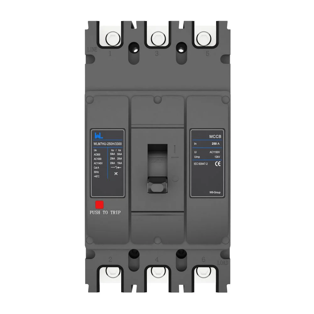
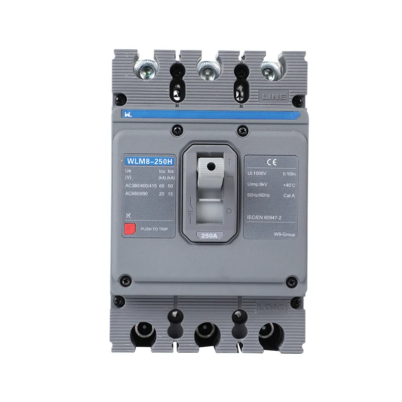
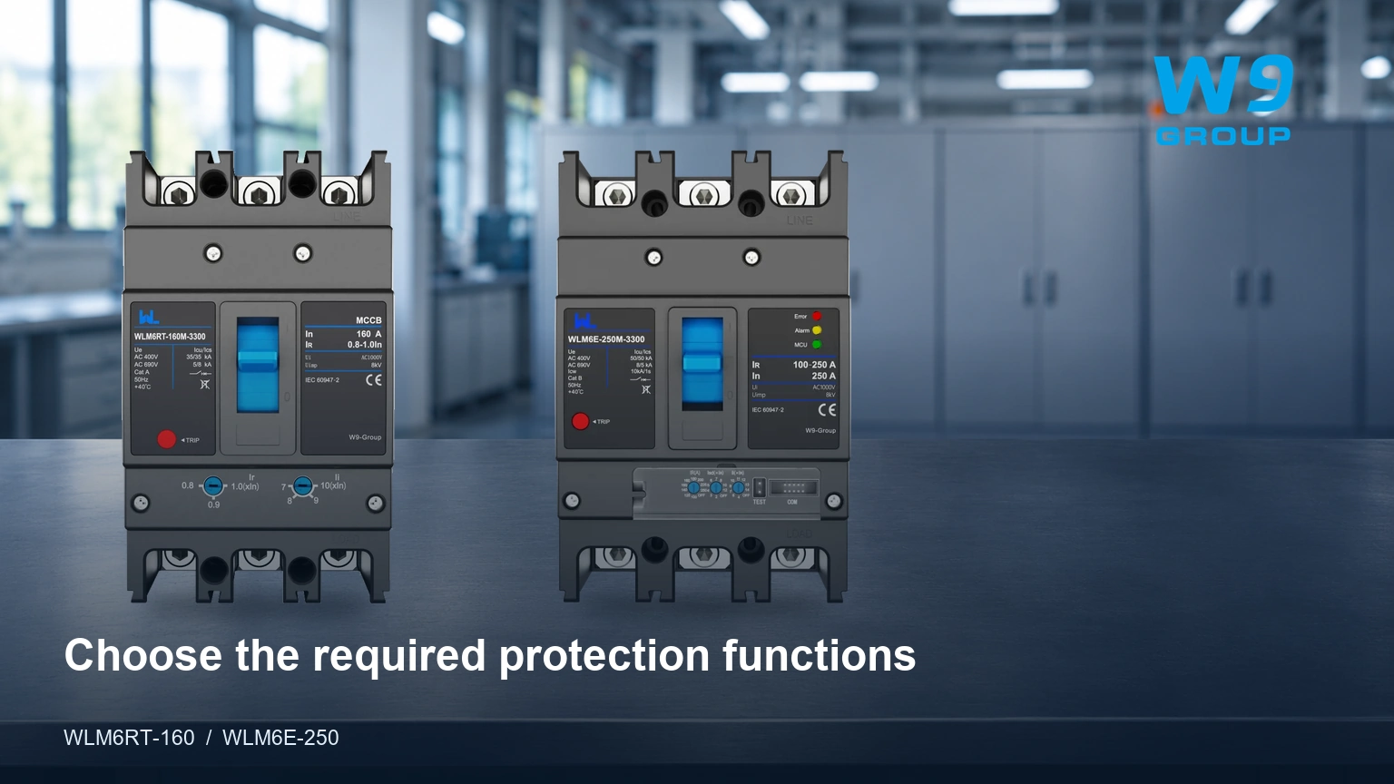
Put four decisions into the enquiry: the required protection functions, acceptable curve and setting ranges, the complete breaker ratings, and the commissioning evidence. W9 Group’s WLM6E electronic MCCB is an enquiry starting point; the supplied release version and any communications or ground-fault options should be identified separately.
Ask for trip-unit tolerance data where accuracy affects the design, and retain a commissioning settings record for either option. A device that meets the study when delivered can cease to meet it after an undocumented adjustment or substitution.
Thermal-Magnetic and Electronic Trip Questions
What is the difference between thermal-magnetic and electronic trips?
The first uses thermal and magnetic release mechanisms; the second evaluates sensed current electronically. Compare actual functions and response data, because the release name does not establish every feature.
Which thermal-magnetic circuit breaker is best?
The appropriate breaker is the one whose documented ratings and curve satisfy the circuit. There is no defensible universal best choice without a voltage, fault level, load profile and installation specification.
Where can I find the correct breaker manual?
Request the document matching the manufacturer, frame, release and accessories. A generic family catalogue may omit the adjustment limits or test procedure required for the installed version.
How does a thermal-magnetic release work?
Current-related heating operates the overload function and magnetic actuation provides high-current pickup. Both release the mechanism, while the complete breaker performs interruption.
What is a thermal-magnetic circuit breaker used for?
It is used for suitable distribution and equipment overcurrent duties. Additional functions such as residual-current detection or specialised motor protection require separate confirmation.
How does a thermal circuit breaker respond to an overload?
Its thermal element responds over time to heating. The actual response depends on current, initial temperature and the manufacturer’s operating characteristic.
References
- IEC 60947-2:2024 — industrial circuit-breaker scope.
- HSE HSG85 — safe electrical working practices.
- HSE — equipment maintenance and inspection planning. Sources checked 2 November 2026.
Buy the protection functions your project can specify, commission and maintain. Review W9 Group’s MCCB range and request a quotation with the required release functions so the two offers can be compared on the same basis.