


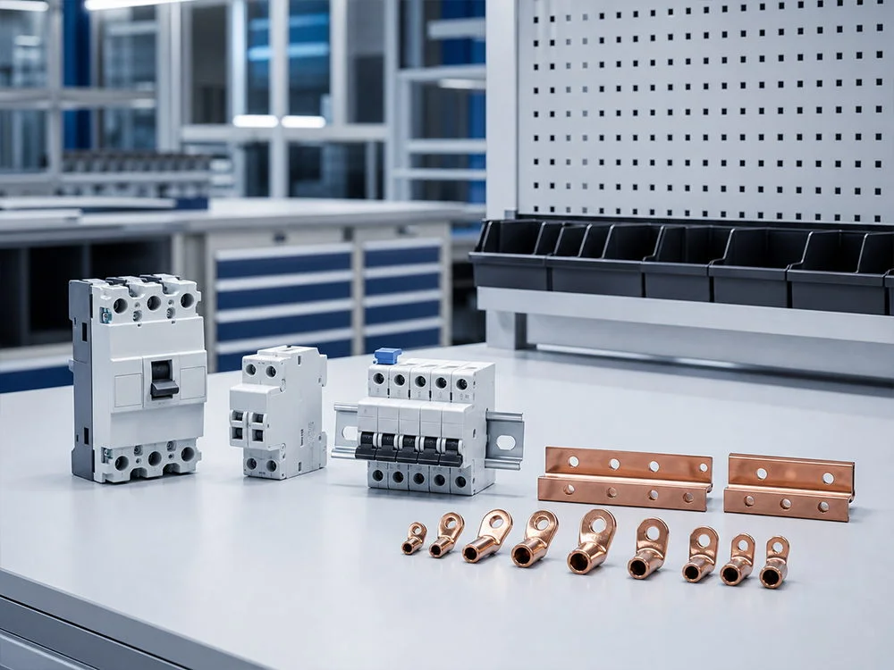






MCCB Auxiliary Contacts vs Shunt Releases
A control panel may need to report whether a breaker is open and also open that breaker on a remote command. Ordering an accessory for “remote control” does not adequately describe either requirement. The indication circuit and the opening circuit perform different jobs, and selecting one accessory cannot be assumed to provide both.
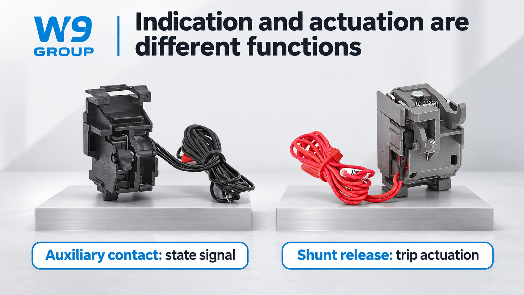
An MCCB auxiliary contact provides a signal associated with a documented breaker state. A shunt release receives an electrical command that operates the opening mechanism. Neither function automatically identifies why a protection trip occurred. Specify indication, commanded opening and fault-trip reporting separately, then match each accessory to the exact host breaker.
Separate status indication from a trip command
An auxiliary contact changes its contact state according to the manufacturer’s stated relationship with the breaker mechanism. The control system interprets that contact through a suitably designed signal circuit. The contact does not independently power the controller, detect a fault or open the main circuit. Its electrical rating and state table must suit the intended signal duty.
A shunt release for an MCCB is an actuator. It needs the specified supply and command conditions to operate. Do not assume that an accessory with the right physical outline accepts the available AC or DC control voltage. Likewise, a device intended for a defined operating duty must not be treated as suitable for a permanently applied command unless the manufacturer confirms that use.
A fault-trip alarm contact is another distinction. Its purpose is to indicate the documented trip condition, which may differ from simple open or closed position feedback. The exact response to manual opening, protective tripping, remote opening and reset must come from the product’s state table. A signal name such as “breaker fault” in a controller does not change what the installed contact physically indicates.
| Accessory | Required task | Essential selection information |
|---|---|---|
| Auxiliary contact | Report a defined operating position | State table, contact duty and approved host |
| Shunt release | Initiate opening on a valid command | Supply, operating duty and approved host |
| Fault-trip alarm contact | Report the specified trip condition | Event response and reset behavior |
| Motor operating accessory | Provide its specified mechanical operating functions | Exact permitted operations and interlocks |
Specify contact duty and coil supply separately
The main breaker’s current rating does not establish an auxiliary contact’s switching capability. The signal circuit has its own voltage, current and load characteristics. Request the accessory’s documented contact ratings for the intended duty and, where relevant, its minimum switching load. A contact suitable for one control load may not be suitable for a different input circuit.
The shunt release has a separate electrical specification. Identify AC or DC operation, the relevant rated supply and any stated restrictions on command duration or repetition. Ask how the release behaves during reset and whether additional control logic is required. If the documentation does not answer those questions, keep them open in the design review instead of making assumptions from a catalogue photograph.
The wider protection design also matters. A shunt release may be commanded by a separate detector or supervisory system, but the release alone does not create a protection function. For example, MCCB earth-leakage protection requires an appropriate sensing and decision arrangement as well as a means of opening the circuit.
Use the exact accessory diagram for wiring
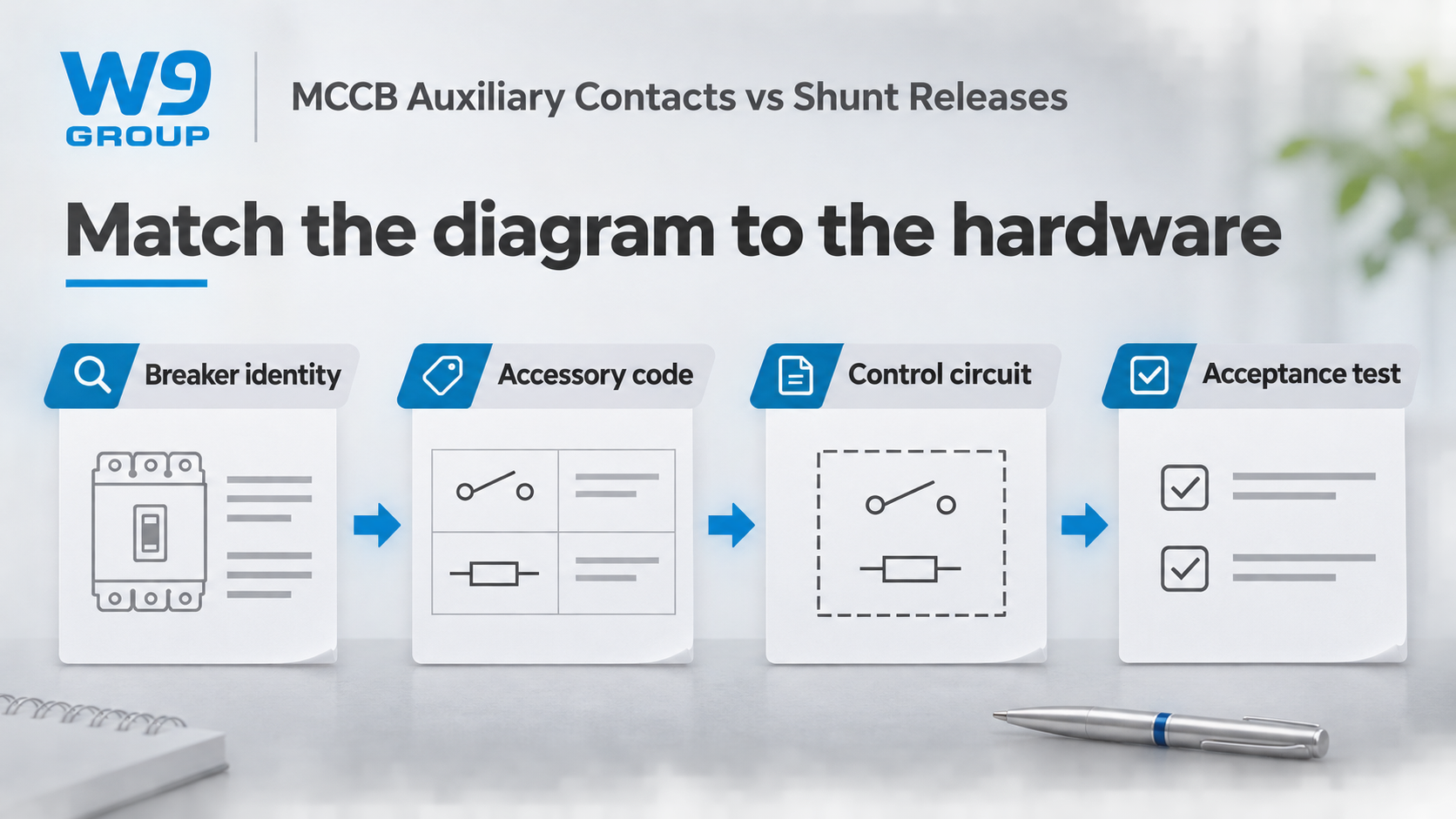
Begin with the full breaker designation, accessory code and document revision. The drawing must identify the accessory terminals or leads and the conditions under which its symbols are shown. Different manufacturers can use different conventions, and even related product generations may not share a wiring arrangement. Wire color or physical position is not an adequate substitute for the approved diagram.
For an indication circuit, record the expected state at the actual controller input for each required breaker condition. For a commanded opening circuit, identify the command source, supply and approved release arrangement. This is a functional specification for qualified designers and commissioning personnel, not a generic instruction to connect terminals found on an unfamiliar device.
Model-specific wiring documentation should remain with the panel records. If the accessory changes during procurement, review the diagram and input or output configuration before installation. A replacement that physically fits can still reverse the expected indication or require a different supply. Document the change so later maintenance personnel do not troubleshoot against an obsolete drawing.
Confirm mechanical compatibility before approving an accessory
Check the host series, frame, generation, pole arrangement where relevant and permitted mounting position. Accessory space may also be affected by other fitted options. Ask the manufacturer to confirm the complete combination rather than approving each accessory independently and assuming that all of them can be installed together.
Distinguish factory-fitted options from permitted field installation. Opening a cover or disturbing the mechanism may fall outside the service instructions for the product. IEC 60947-2 is relevant to the circuit-breaker product requirements, but citing it does not establish that an arbitrary accessory combination preserves the intended performance. The exact product evidence and installation scope still matter.
| Review point | Auxiliary contact question | Shunt release question |
|---|---|---|
| Required function | Which condition must the controller indicate? | Which command must initiate opening? |
| Electrical interface | Does contact duty suit the signal circuit? | Does the supply match the release specification? |
| Mechanical interface | Is the location approved for this host? | Is this release approved for this mechanism? |
| Commissioning | Are the required states represented correctly? | Does the approved operating chain perform correctly? |
| Maintenance record | Are terminals and expected states documented? | Are supply, command conditions and reset recorded? |
Test the signal and operating chain as different functions
A changed controller indication does not prove that the main circuit opened. Conversely, a breaker that opens correctly may still have an incorrect feedback signal. The acceptance procedure should therefore distinguish the operating result from the indication result. Tests must be performed by competent personnel under the manufacturer’s procedure and the site’s electrical-safety arrangements.
Record the initial condition, commanded event, actual breaker response and resulting indications. Include the test method and any limits on its coverage. An indication check, a release function check and protection performance testing are not interchangeable. HSE guidance supports planned maintenance based on equipment, environment and previous findings rather than an undocumented trial-and-error approach.
Separate acceptance criteria also improve purchasing decisions. A quotation should state which accessories, diagrams and commissioning provisions are included. Compare the cost of completing the required functions, including engineering and testing, rather than comparing two accessory prices as though they provide the same capability.
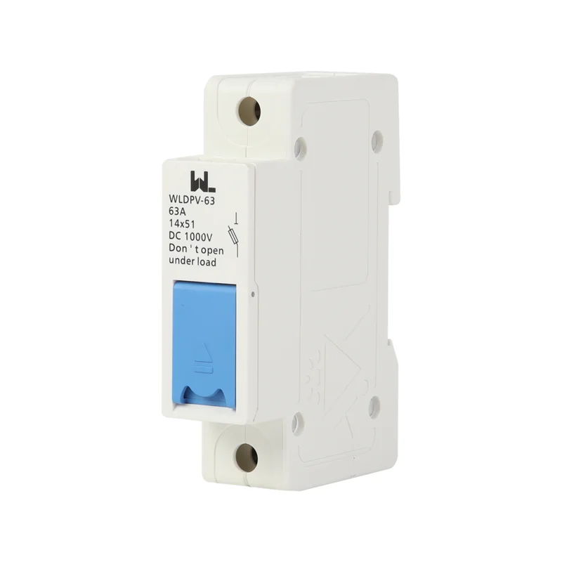
W9 Group’s single auxiliary contact provides a product reference for a position-feedback enquiry. Confirm the exact host, contact duty and state table before using it in a control-system design.
Frequently asked questions
What are these circuit breaker parts called?
Use auxiliary contact for the specified position signal and shunt release for commanded opening. A fault-trip alarm contact has a different indication role; confirm the manufacturer’s exact terminology and codes.
Are the control relay and power supply part of the breaker?
They may be separate panel components. Define the supply boundary and responsibility for the complete control circuit so the accessory order does not omit equipment needed by the design.
Do the four basic circuit elements identify the required accessory?
No. Source, conductors, load and control are general circuit concepts. Accessory selection needs the specific indication or opening function and its electrical and mechanical interfaces.
Can an incorrect shunt release supply damage the accessory?
An unsuitable supply or operating duty can cause malfunction or damage. Use only the documented conditions; do not use a guessed voltage or repeated energization as a diagnostic method.
What should an accessory wiring diagram show?
It should identify the exact accessory, its terminals or leads, the reference state and relevant supply or contact requirements. Keep its revision matched to the installed equipment.
Can a local supplier provide an interchangeable accessory?
Only documented compatibility can establish that. Proximity and a similar photograph do not prove the accessory fits the host or performs the required function.
References
- IEC 60947-2:2024, circuit-breaker standard scope.
- HSE HSG85, safe working practices for electrical equipment.
- HSE, Maintaining electrical equipment safety.
Request the right MCCB accessory
For commanded opening, review W9 Group’s shunt release accessory. Send the complete breaker code, required opening function and control-circuit specification when requesting a quotation. Ask for the approved combination and its matched documentation before installation.