








How to Select MCCB Earth-Leakage Settings
A feeder begins tripping after several electronic loads are added. Someone proposes increasing the leakage setting until the interruptions stop. In this hypothetical scenario, that adjustment could hide an insulation problem or undermine the required protection. The first task is to understand what changed, not to choose a more convenient threshold.
MCCB earth-leakage settings must follow the protection objective, installation requirements, connected-load behavior and the exact release specification. Sensitivity and time delay are separate decisions. Neither can be inferred from the breaker frame current, and a residual making or breaking rating is not a leakage pickup value.
Leakage Pickup Current and Trip Delay
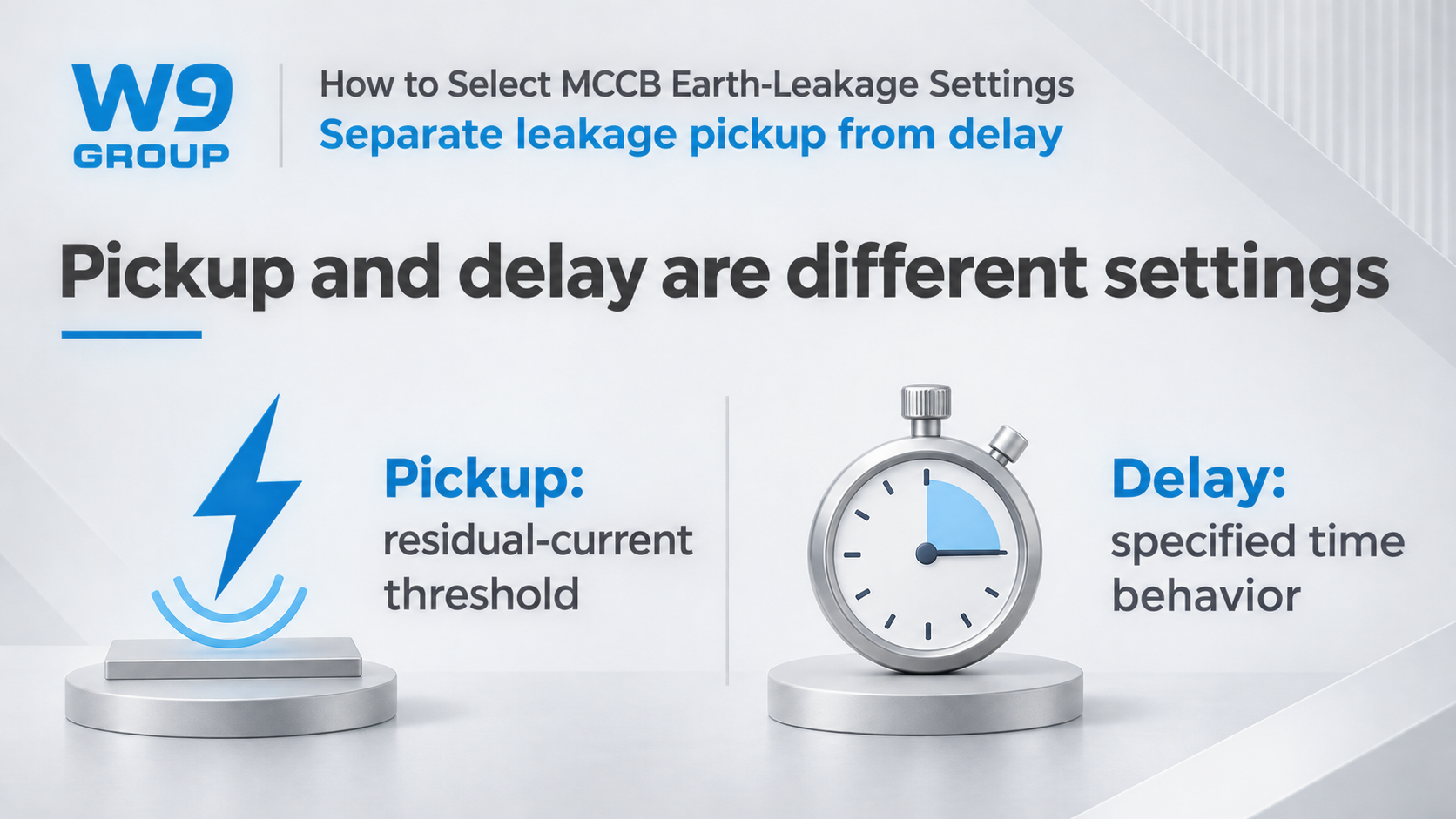
Pickup describes the specified residual-current threshold. Delay describes the time behavior associated with operation. The manufacturer’s terminology, reference conditions and tolerances matter, so a single number copied from a family brochure is not a complete setting specification.
Do not assume that a listed delay is a guaranteed total disconnection time. A document may describe a non-actuating interval, an intentional delay or another characteristic. The complete operating and interruption behavior must be assessed against the installation’s required disconnection criteria.
For the broader distinction between electronic protection functions and their settings, see the electronic MCCB trip-unit guide. A controller’s technology does not establish its sensitivity range or the availability of every residual-current function.
| Quantity | Meaning | Common mistake |
|---|---|---|
| Selected current or frame designation | The identified breaker or current-carrying duty | Using it as the leakage threshold |
| Residual operating current | The specified leakage pickup characteristic | Ignoring waveform and time requirements |
| Time characteristic | The documented delay or response behavior | Treating a non-actuating interval as total clearing time |
| Residual making or breaking capacity | A declared switching-duty quantity | Reading it as sensitivity |
Shock Protection and Equipment Protection
The design may require automatic disconnection, additional protection against electric shock or a specific equipment-protection function. Write that objective into the setting schedule. The earthing arrangement, circuit use and applicable installation rules determine which criteria must be met.
HSE discusses RCDs rated at no more than 30 mA for limiting certain electric-shock risks, while explaining that they cannot protect against every type of shock. That guidance is not a universal feeder setting. A different residual-current duty may have different design requirements, and the selected MCCB may not offer the sensitivity required for additional protection.
A higher threshold is not a fault remedy. If the existing device trips, investigate the circuit and connected equipment before changing the setting. A change is acceptable only when the responsible design assessment shows that the required protection is still provided.
Likewise, the lowest available pickup is not automatically the best setting for every upstream feeder. The complete design must account for normal residual behavior, required disconnection and coordination with downstream protection. Those constraints need to be resolved together rather than ranked by a generic rule of thumb.
Normal Leakage and Residual-Current Waveforms
Identify the connected loads and their operating modes. Electronic equipment can have normal leakage contributions, and several loads may contribute to the residual current seen by one upstream device. Starting, switching and changes in equipment condition can alter the observed pattern.
Measurements should be made by a competent person using a method and instrument suitable for the installation and relevant waveform. Record the operating conditions with the results. An isolated reading with no description of which loads were running provides a weak basis for changing a protective setting.
The release’s residual waveform response must match the requirement. Type labels are not interchangeable, and the word electronic does not prove that a device responds to every residual-current form. Obtain the connected equipment’s requirements and the exact protective-device declaration.
Waveform suitability comes before fine-tuning sensitivity. Adjusting the pickup of an unsuitable response type does not turn it into a suitable device. If the required behavior cannot be established from the documentation, resolve the product selection before proceeding to a setting value.
Upstream Leakage Delays and Downstream Selectivity
Where an upstream delay is proposed, check the exact upstream and downstream characteristics and the installation’s maximum permitted disconnection time. Different sensitivity values alone do not establish selectivity. Neither does a generic time interval copied from another manufacturer’s family.
Any alarm-only mode must be documented separately from tripping protection. A useful maintenance alarm can support investigation, but it does not satisfy a requirement for automatic disconnection by itself. The schedule should state which action is required and which mode is actually supplied.
For an external earth-leakage relay arrangement, the sensing device, relay, trip actuator and switching device form a system. Request evidence for the complete supported arrangement. A relay pickup value alone does not demonstrate the operating time or suitability of the entire trip chain.
| Design input | Decision it supports | Evidence to retain |
|---|---|---|
| Protection objective and earthing arrangement | Required residual-current function | Approved design basis and applicable requirements |
| Load behavior and measured leakage | Assessment of normal operation and faults | Measurement conditions and equipment information |
| Upstream and downstream devices | Permitted coordination and delay | Exact characteristics and coordination assessment |
| Supplied release and trip arrangement | Available pickup, time behavior and action | Matching manual, order code and test instructions |
Testing and Recording WLM6LY Leakage Settings
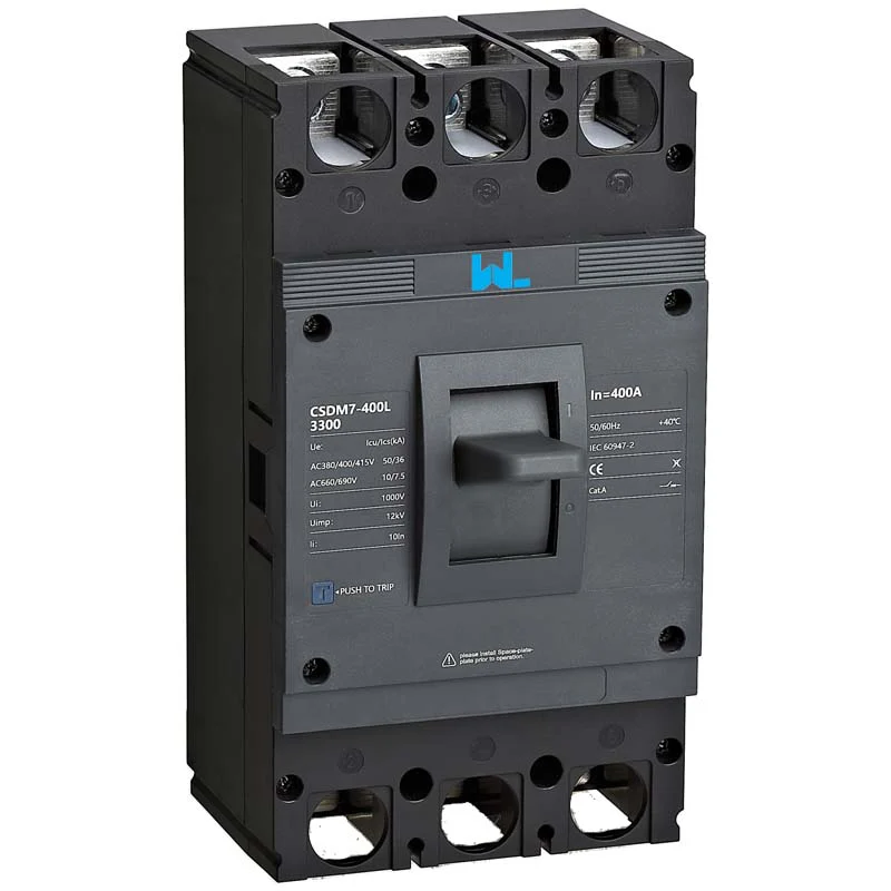
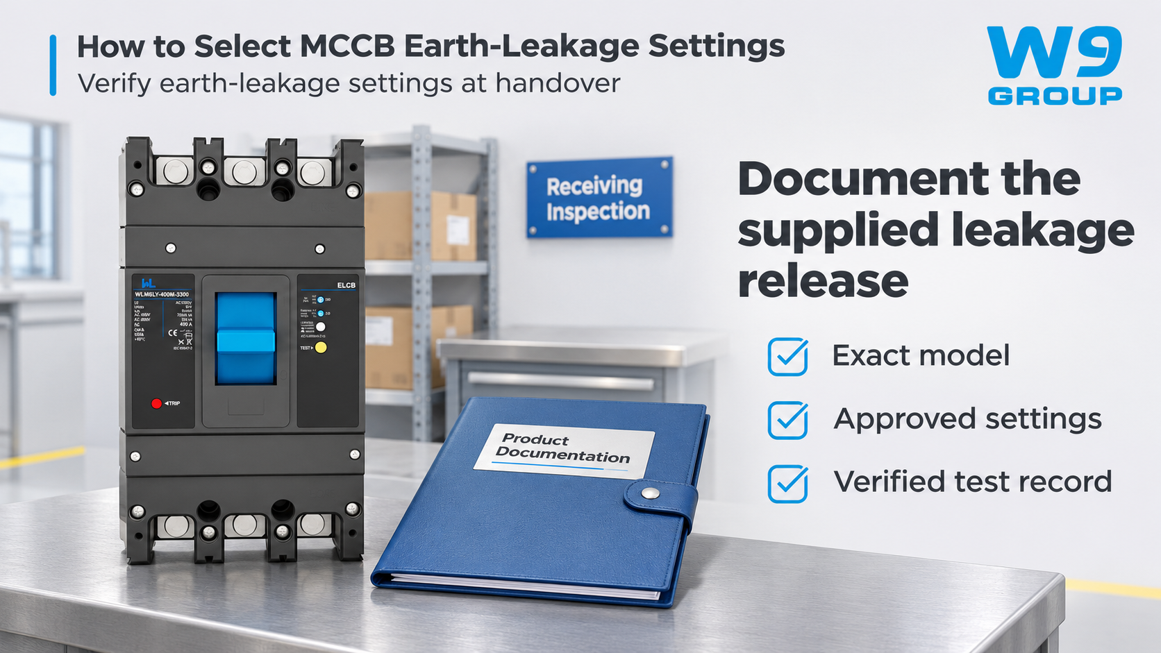
W9’s WLM6LY-400 earth-leakage MCCB page lists a thermal overcurrent release, an electronic leakage release and AC residual-current response. It also asks buyers to confirm the available sensitivity and delay for the exact configuration. Do not substitute another model’s setting table.
The native table includes delay-related values under wording that mixes a time-unit heading and second-based entries. Treat that as a documentation item to resolve, not as permission to publish a recommended delay. Obtain the matching manufacturer’s definition and characteristic before assigning a setting.
IEC 60947-2 supplies the industrial circuit-breaker standard context. Its public scope does not provide a setting schedule for an unidentified installation or certify a proposed configuration. HSE safe-working guidance also applies: this article is a selection guide, not an instruction for live adjustment or improvised testing.
- Record the exact breaker, release and approved protection objective.
- Confirm the supported pickup, time behavior, response type and trip mode.
- Use the specified commissioning method and acceptance criteria.
- Retain the measured results, final settings and authorization for changes.
Send missing information through W9 technical enquiries. The final setting needs a documented acceptance basis. That record is valuable during later troubleshooting and makes clear which assumptions were checked at commissioning.
MCCB Earth-Leakage Settings FAQ
Can a Two-Pole MCCB Meet the Circuit’s Leakage Requirements?
When the supported two-pole configuration matches the circuit’s supply, switching and sensing requirements. Confirm the neutral and test-circuit arrangement from the exact manufacturer’s drawing.
Which Model Details Are Needed to Obtain the Correct MCCB Manual?
Request the manual using the complete breaker and leakage-release codes, including relevant suffixes. A similar product photograph or family brochure is not enough to establish setting references and test instructions.
What Should an Earth-Leakage Protection Quotation Include?
The complete protection arrangement, release options, accessories and commissioning requirements affect cost. Compare quotations that include the same functions and documentation rather than only the breaker price.
Does the Earth-Leakage Breaker Name Define All Its Functions?
It is a broad term for a device that responds to the specified leakage condition. Confirm its actual product class, operating principle and whether overcurrent protection is included.
Is a Leakage Alarm Equivalent to Automatic Disconnection?
It performs the declared action when the relevant leakage condition is detected. Confirm tripping versus alarm behavior; an alarm-only function must not be mistaken for automatic disconnection.
Should the Leakage Pickup Be Increased After a Trip?
Preserve available evidence and have the circuit assessed under safe isolation arrangements. Do not repeatedly reset or increase the pickup without resolving the fault and confirming the protection design.
References
- IEC 60947-2:2024: circuit-breaker scope and edition information
- HSE electrical safety FAQ: RCD use and limitations
- HSE HSG85: safe working practices
A defensible setting follows the protection objective and the actual device. Explore the W9 circuit-protection range and contact the team with the sensitivity, waveform and time requirements established for your project.