








How to Diagnose MCCB Shunt Trip and Auxiliary Contact Faults
A remote trip command is issued, but the expected breaker indication does not change. That observation leaves several possibilities: the command was not delivered, the control supply was unsuitable, the opening accessory did not operate, or the feedback circuit reported the wrong state. Replacing the shunt release immediately may leave the actual fault untouched.
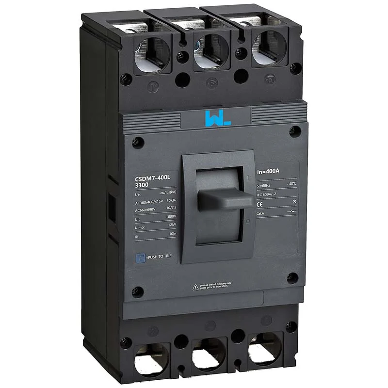
Useful MCCB accessory fault diagnosis separates the command, operating and indication functions. Establish what the breaker actually did, identify the exact accessory, and choose tests that address the unresolved part of the chain. There is no universal coil-resistance value or improvised power-supply test that can establish the condition of every shunt release.
Record the symptom before disturbing the circuit
Preserve available event records, controller messages and observed operating conditions. State whether the breaker failed to open, opened without the expected indication, or produced an unexpected signal. These are different symptoms. A screen message may reflect a configured input rather than the main contact position, so keep the displayed state and the physical operating result separate in the record.
Identify the host breaker, accessory code, documented electrical requirements and relevant drawing revision. Note recent changes to the control supply, controller logic, wiring or installed accessory. A fault beginning after modification suggests where to investigate, but timing alone is not proof of the cause. Record the change history without replacing evidence with an assumption.
The wider installation may include electronic protection, external relays and several control sources. The electronic MCCB troubleshooting guide helps distinguish protection behavior from surrounding control-system issues. Testing must still follow the exact manufacturer’s instructions and the site’s approved safe-working arrangements.
Trace the trip command before condemning the coil
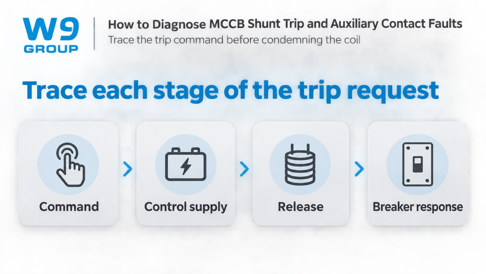
Begin with the intended functional sequence: a valid command, an appropriate control supply, delivery through the approved circuit, operation of the release and opening of the breaker. Review the documents and available records to find which part of that sequence is unproven. This is a diagnostic framework, not a generic terminal-by-terminal energized test procedure.
A shunt-trip control-supply fault can resemble a failed release. The relevant question is whether the specified conditions are available at the required time and location under the manufacturer’s test method. The existence of a nominal supply elsewhere in the cabinet does not establish that the accessory received a valid command.
Command duration and operating duty also matter. Do not apply a guessed voltage, leave a coil energized indefinitely or repeatedly pulse it to see whether it responds. Different releases have different documented requirements. If the exact procedure is unavailable, obtain it before conducting the dependent test rather than turning an uncertain diagnosis into additional damage.
| Observed symptom | Function to investigate | Evidence needed |
|---|---|---|
| No commanded opening | Command, supply, release and mechanism | Approved functional test and exact accessory requirements |
| Breaker opens but indication stays unchanged | Feedback contact and signal circuit | State table, actual operating state and controller input record |
| Unexpected remote opening | Command source and control logic | Event history and relevant circuit records |
| Intermittent feedback | Signal path and documented contact duty | Operating conditions and suitable inspection or test findings |
| Problem begins after replacement | Identity, compatibility and installation | Old and new part codes and matched instructions |
Compare auxiliary-contact signals with the correct state table
An auxiliary contact reports its specified relationship to the breaker mechanism. A trip-alarm contact may have a different response. Before declaring a contact faulty, confirm which accessory is installed and what the relevant state table says about manual opening, closing, tripping and reset. Do not expect every contact to identify every kind of trip.
Then separate contact behavior from the rest of the signal circuit. Wiring, input supply, controller configuration and indication logic can affect what an operator sees. A control-system screen that says “closed” does not independently prove main-contact closure. Likewise, an open indication does not establish that the installation is safely isolated for work.
Auxiliary-contact testing requires a method suited to the specified contact duty and installed arrangement. A simple reading taken under undefined conditions may not answer the actual fault question. Use the manufacturer’s procedure and the approved work plan, recording the breaker state and test scope so the result can be interpreted later.
Distinguish electrical faults from installation problems
An accessory may be the wrong variant, installed in an unapproved position or mechanically incompatible with the host. Check the approved combination and installation records before treating poor operation as a manufacturing defect. A similar shape, matching wire count or shared current-rating label cannot establish compatibility.
The complete breaker’s condition also matters. An accessory test cannot prove that damaged internal mechanisms or main contacts are fit for service. Follow the manufacturer’s inspection and service limits. The breaker inspection guide explains why visible condition, operating history and the permitted maintenance scope belong in the assessment.
Where the evidence points to a defective item, preserve its identity and the test findings for supplier review. Do not dismantle a sealed or nonserviceable accessory to create a more detailed diagnosis. If the manufacturer requires return assessment or complete-device replacement, account for that route in the outage plan.
Verify the operating chain before returning the breaker to service
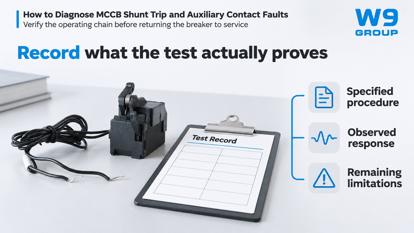
Correcting one defect is not the same as demonstrating the required function. After approved work, verify the relevant operating and indication paths under the applicable procedure. Record which conditions were tested, the actual responses and any exclusions. Where a separate detector commands the release, the acceptance plan must address the intended combination, not only the loose accessory.
Return-to-service verification should also confirm that temporary test arrangements have been removed and authorized settings and drawings are current. These checks belong to competent personnel responsible for the installation. HSE guidance emphasizes safe isolation and maintenance appropriate to the equipment and environment; it does not justify a universal test interval or a shortcut around model-specific instructions.
| Verification item | What to record | What it does not prove alone |
|---|---|---|
| Accessory identity | Installed code and approved host | Correct operation under every condition |
| Commanded opening | Method, initial state and actual result | Correctness of all indication signals |
| Feedback behavior | Required states and observed signals | Safe isolation of the installation |
| Protection-chain function | Included detector, release and breaker scope | Untested protection performance |
| Work completion | Approved changes and remaining limitations | Compliance outside the assessed scope |
IEC 60947-2 provides the circuit-breaker product-standard context. Referencing it in a maintenance record does not certify an improvised test or prove that a substitute accessory is approved. Keep product evidence, service instructions and the site test record connected but distinct.
Frequently asked questions
Which breaker parts are involved in a failed remote trip?
The command source, control supply, circuit, release and operating mechanism may all be relevant. The observed symptom must be narrowed through the applicable procedure before assigning the fault to one part.
Can panel components cause an apparent breaker accessory fault?
Yes. A control-supply issue, field connection or controller configuration can affect opening or indication. Review the complete installed function rather than testing the accessory in isolation without context.
Can a basic four-part circuit model locate the fault?
It can help organize a general explanation, but it cannot supply model-specific acceptance criteria. Diagnosis requires the actual control diagram, accessory specifications and approved testing method.
Can a circuit breaker parts kit resolve an accessory fault?
Only if diagnosis identifies a defective serviceable item and the kit contains the approved replacement. A kit is not a diagnostic method and cannot correct an unresolved supply or controller problem.
Where should I obtain the circuit breaker parts catalogue?
Use the manufacturer or an authorized technical source for the exact host series. Also request the accessory diagram, state table and test instructions; a catalogue alone does not define the diagnostic procedure.
Which accessory types need different fault tests?
Position contacts, trip-alarm contacts and opening releases have different functions and acceptance criteria. Identify the installed type before choosing a test, and use its model-specific procedure.
References
- IEC 60947-2:2024, circuit-breaker standard scope.
- HSE HSG85, Electricity at work: Safe working practices.
- HSE guidance on maintenance, inspection and testing.
Request support with the fault evidence attached
When discussing W9 Group’s MCCB shunt release, provide the full host and accessory codes, control-supply specification, symptom and qualified test findings. Ask for the exact operating and installation documents before further testing. A clear evidence trail helps distinguish a replacement requirement from a control-circuit or configuration correction.