


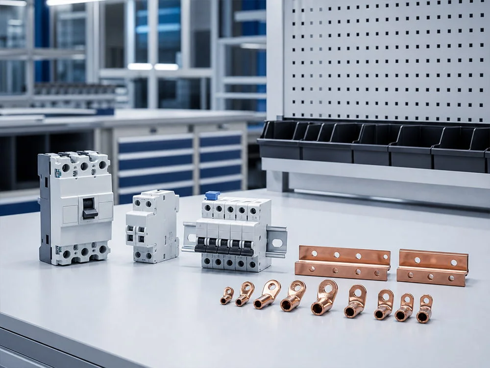

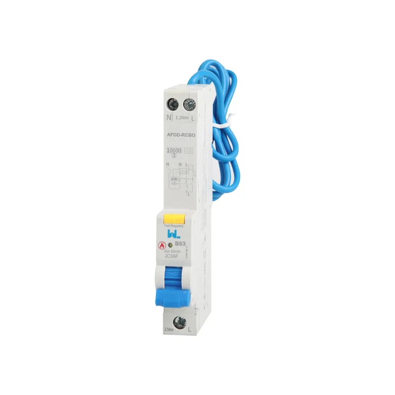
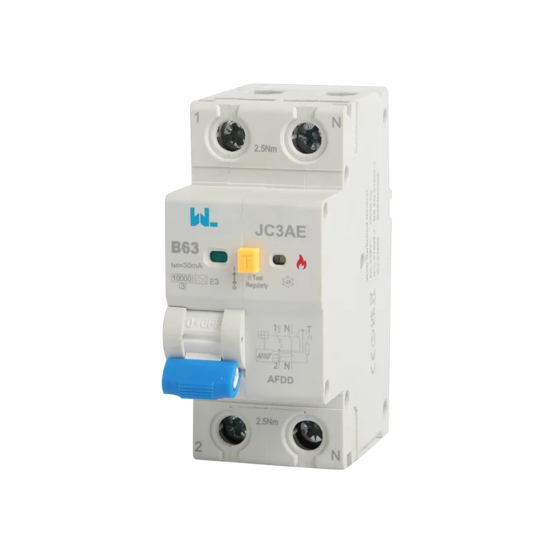
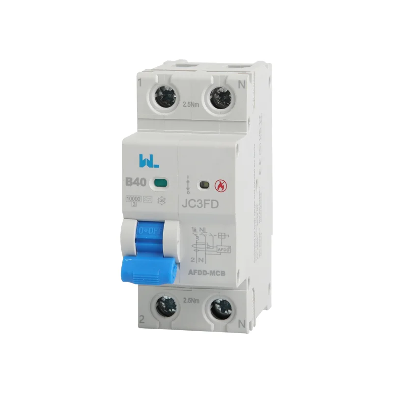
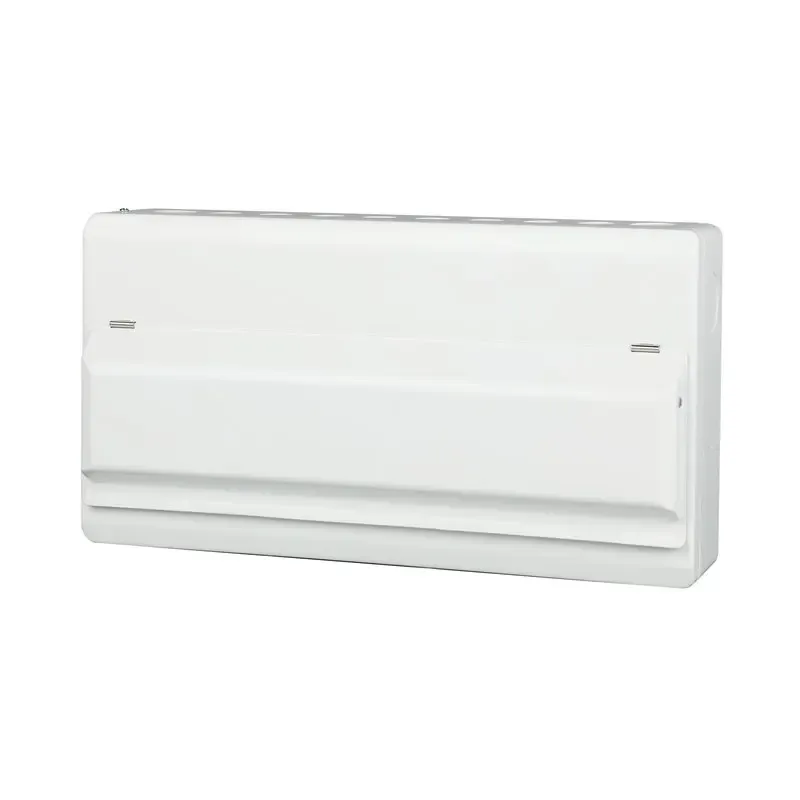





DC MCCB (DC Molded Case Circuit Breaker) Basic Guide
A DC MCCB enquiry needs more than current and a DC label. The available voltage, source fault behaviour, polarity and approved connection determine whether a breaker can interrupt the actual circuit.
DC arc interruption differs from AC because there is no periodic natural current zero. A valid DC rating therefore belongs to a specific device, voltage and connection arrangement. An AC rating cannot be converted by a guessed factor.
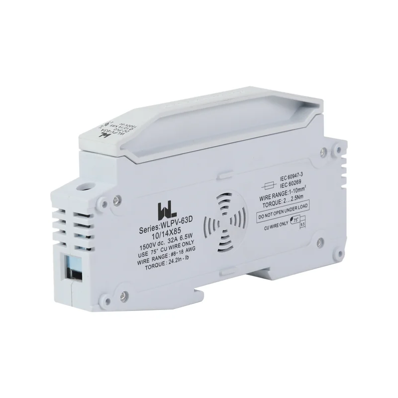
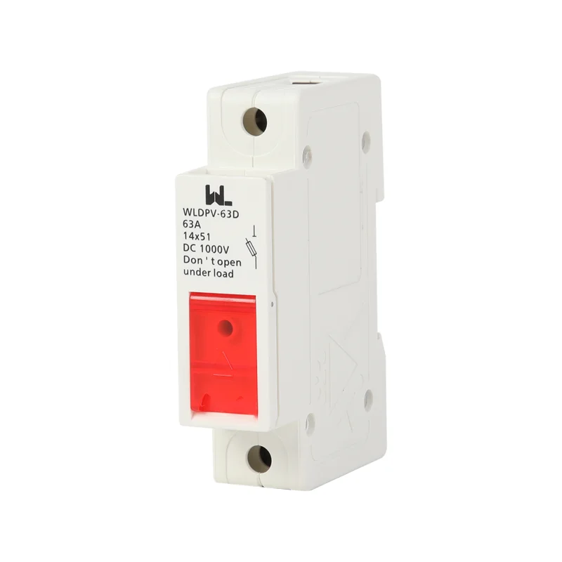
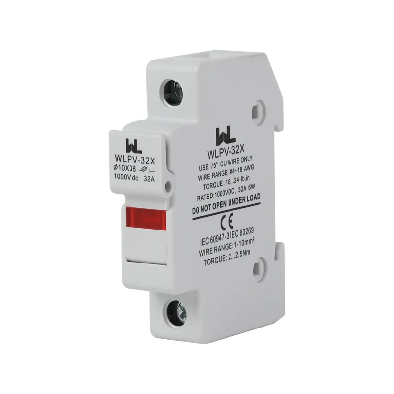
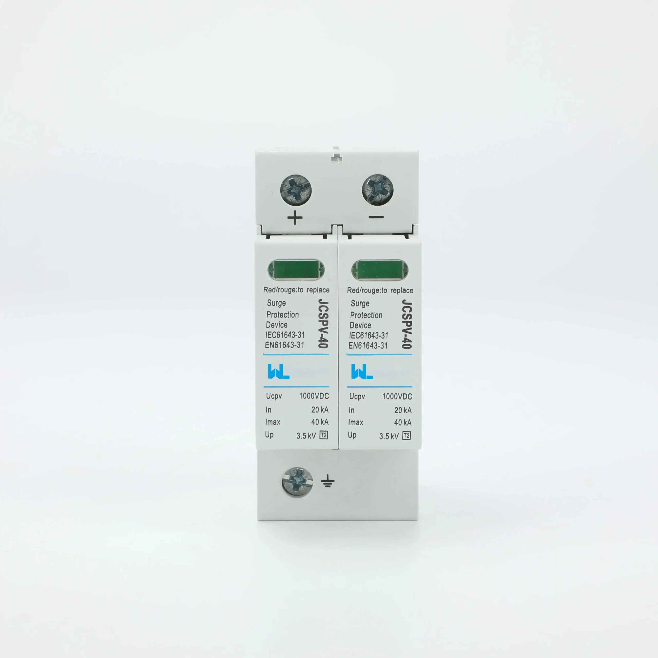
Review the photovoltaic protection range against the maximum DC voltage and permitted pole connection.
Define the source and maximum voltage
For PV, establish maximum operating voltage under the design conditions and parallel-source contributions. For batteries, obtain prospective fault current and stored-energy information. For rectifier-fed circuits, the source impedance and source time constant can affect interruption duty. These are not interchangeable assumptions.
Record earthing and whether current direction can reverse. A polarity-sensitive device must follow its approved diagram. Even a non-polarity declaration does not permit arbitrary pole connections or every source application.
The photovoltaic distribution guide distinguishes PV-string assumptions from battery fault-current duties.
Match the rating to the approved pole arrangement
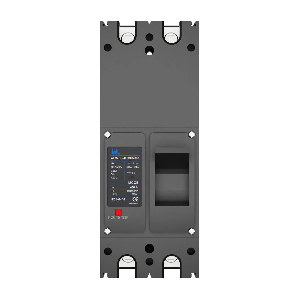
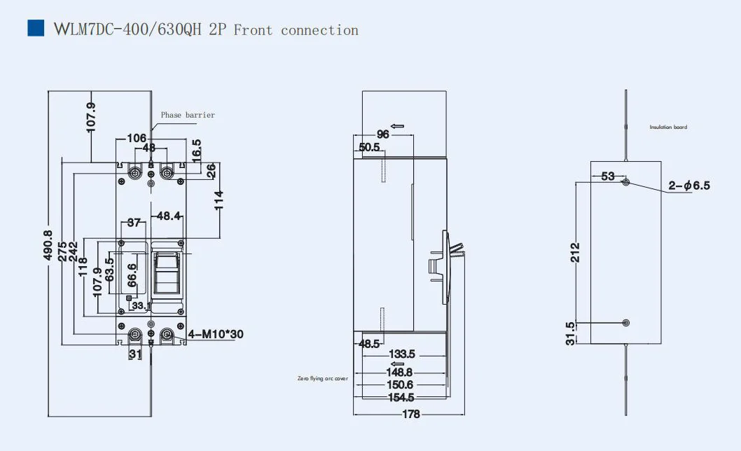
Read voltage-specific fault data for the exact model and permitted pole connection. Multiple poles may have a specified series arrangement; that is a manufacturer instruction, not a field design shortcut. The protective conductor is not a switched live path.
| Input | Why it matters |
|---|---|
| Maximum voltage | Insulation and interruption duty |
| Fault current | Required breaking capacity |
| Source behaviour | Current rise and available energy |
| Polarity and earthing | Permitted connection and interruption path |
| Operating current | Conductor and thermal protection |
Coordinate protection and isolation
An MCCB’s overcurrent release must protect conductors and coordinate with other devices. A PV string, battery feeder and converter input can need different settings and equipment. Confirm the declared isolation function and the actual means of safely separating every source for maintenance.
| Application | Specific review |
|---|---|
| PV combiner | Parallel contributions and maximum array voltage |
| Battery feeder | Fault energy and current direction |
| DC industrial load | Starting or regenerative operation |
| Converter circuit | Manufacturer protection and isolation instructions |
Procurement and acceptance
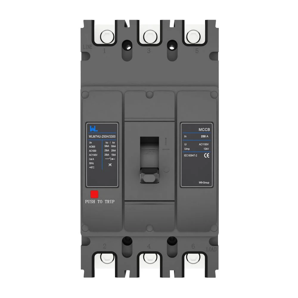
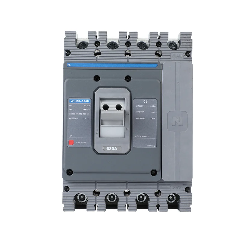
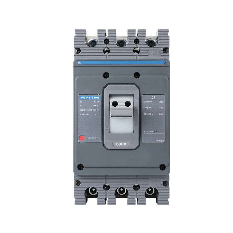
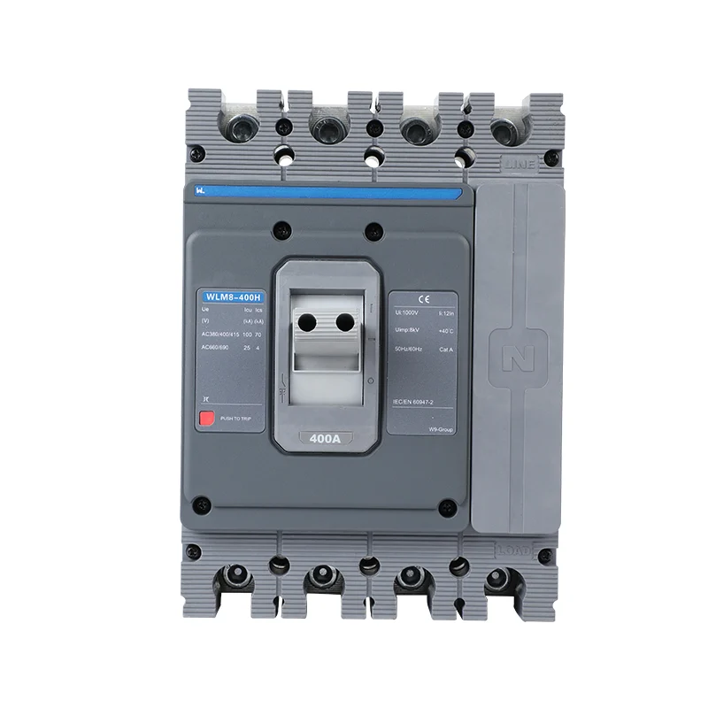
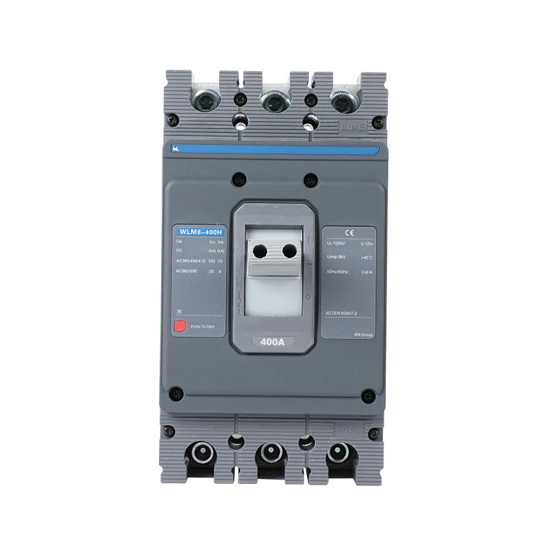
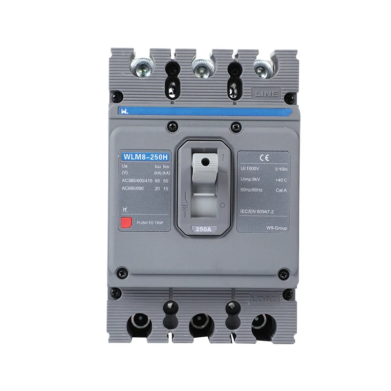
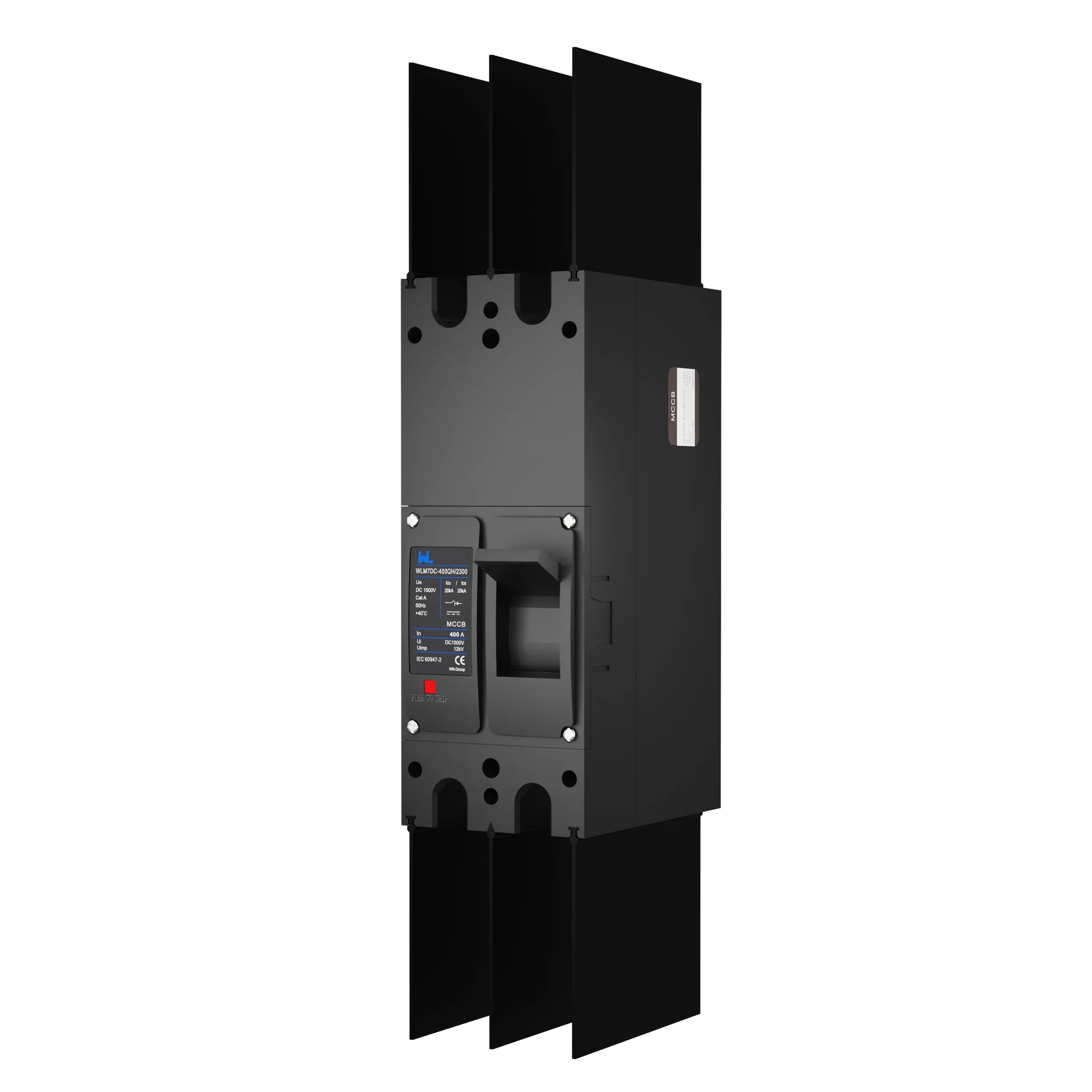
Request the full order code, DC rating table, permitted wiring, trip curves, terminals and installation limits. IEC 60947-2 context does not approve a device outside its declared duty. A photograph or generic solar description is insufficient evidence.
For W9 selection, provide the source data and one-line diagram and ask for the exact supported configuration. Retain the approved drawing with the order and verify the delivered markings before installation.
Frequently asked questions
Why is DC MCCB selection different from AC?
DC lacks periodic natural current zero and needs explicit interruption evidence for the source and connection. AC ratings do not establish DC capability.
What DC ratings are essential?
Confirm maximum voltage, operating current, fault capacity, polarity, permitted pole arrangement and relevant source conditions for the exact model.
Can a PV MCCB be used on a battery?
Only with explicit evidence for the actual battery fault duty and connection. A PV application label alone is insufficient.
Can I series-connect poles to raise voltage capacity?
Only as the exact manufacturer-approved diagram permits. Do not combine pole ratings arbitrarily.
References
- IEC 60947-2:2024 — circuit-breaker product scope.
- IEC 60364-7-712:2025 — photovoltaic electrical installations.
- IEC 60947-3 consolidated edition — switches, disconnectors and switch-disconnectors.
For a PV or DC selection, contact W9 Group with maximum voltage, operating and fault current, earthing and the intended pole connection.