































Technical Requirements for MCCB: A Practical Specification Guide
Technical Requirements for MCCB: A Practical Specification Guide
When a panel engineer in Manchester added a 400 A feeder for a packaging line, the first energisation ended with an immediate trip and a rejected submittal. The replacement breaker behaved no better. A fault-level review revealed the real problem: the schedule listed frame current but not the required breaking capacity, trip settings or accessory voltage. The failure was specification and coordination—not proof that the product family was bad.
Summary: A reliable molded-case circuit breaker (MCCB) specification separates rated operational voltage (Ue), insulation voltage (Ui), impulse withstand (Uimp), rated current (In), and ultimate/service breaking capacities (Icu/Ics). Start with a load and prospective-fault study, apply IEC 60947-1 and IEC 60947-2 (or the destination market’s adopted equivalent), then require model-specific test evidence and traceable labels before release.
An MCCB combines a molded insulating case, contacts, terminals and an overcurrent trip mechanism. It commonly protects building feeders, motors, photovoltaic (PV) distribution and bus sections against overloads and short circuits. The following requirements turn a catalogue request into an auditable purchase specification and a smoother commissioning record.
1. Define the electrical duty before choosing a frame
Record the system voltage and frequency, earthing arrangement, continuous design current, ambient temperature, installation method and prospective short-circuit current at the MCCB terminals. IEC 60947-1 sets common terms and conditions for low-voltage switchgear; IEC 60947-2 adds circuit-breaker ratings and test sequences. A frame number alone cannot establish suitability.
- Ue: match the actual AC or DC operating voltage, including line-to-line and neutral arrangements.
- Ui and Uimp: check insulation and impulse withstand against pollution, altitude and surge exposure in the enclosure.
- In: select from calculated design current after derating; do not copy a cable’s headline ampacity.
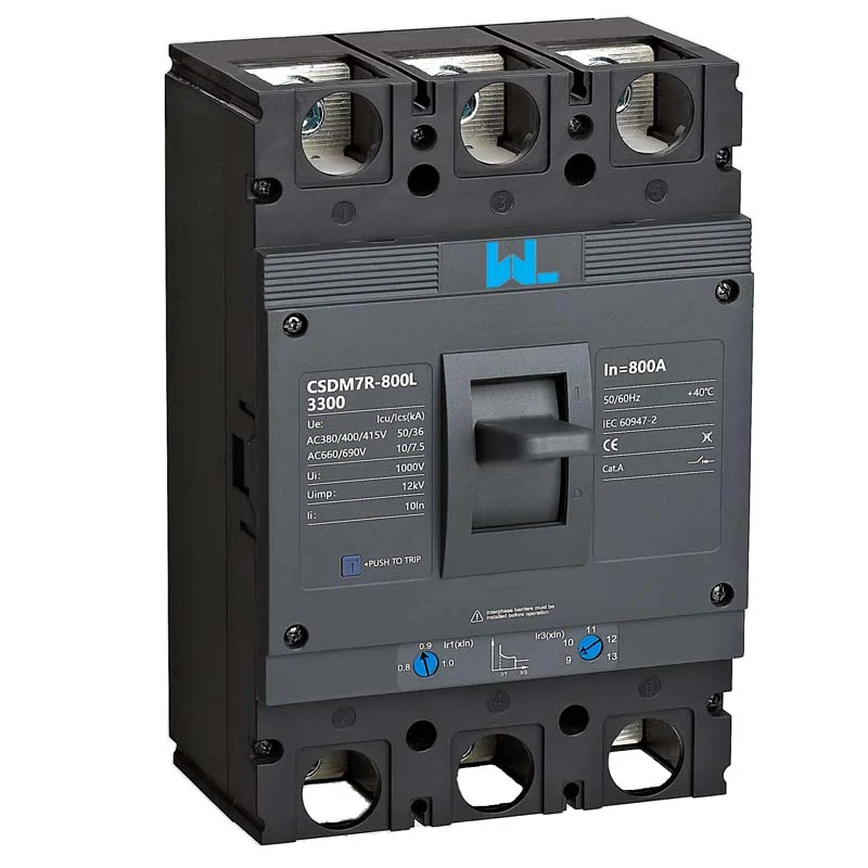
- Icu and Ics: Icu is ultimate short-circuit breaking capacity, while Ics indicates the service level after the standard test sequence. Both must be stated at the relevant voltage.
For a three-phase feeder, verify all poles, neutral treatment and terminal temperature rise as one assembly. A larger frame with an unsuitable trip unit can still leave conductors unprotected. A time-current coordination study should demonstrate discrimination with upstream and downstream devices.
2. Specify trip technology, terminals and mechanical design
Thermal-magnetic protection uses a bimetal for sustained overload and an electromagnetic release for high-current faults. Electronic trip units can add adjustable long-time, short-time, instantaneous and ground-fault functions; they also introduce control-power and verification requirements. Ask for the manufacturer’s declared test configuration—an accessory combination is not automatically covered because the base breaker passed a test.
Write mechanical details into the same schedule:
- State pole count, fixed or draw-out mounting, line/load orientation and terminal style. “Standard terminals” is not an engineering requirement.
- Describe handle type, padlocking or interlocking, and ON/OFF/TRIP indication. Use consistent symbols and labels that match the panel drawings.
- List accessories—auxiliary contacts, alarm contacts, shunt release, undervoltage release, motor operator or rotary handle—by function and rated control voltage.
- Set environmental limits for ambient temperature, altitude, humidity, enclosure ingress protection and vibration; request derating curves when conditions differ from catalogue tests.
Accessories are part of the control narrative. A shunt release may provide emergency isolation, while an auxiliary contact reports status to a PLC. Each requires a wiring diagram, compatibility confirmation and a functional test point.
3. Build a comparison that exposes total cost
The lowest unit price can become the highest installed cost when a breaker needs a second shipment, field modification or redesign after the fault study. Include engineering hours, panel space, commissioning, spares, documentation and outage exposure in total cost of ownership (TCO). The matrix below keeps technical and commercial criteria visible.
| Specification dimension | Basic fixed MCCB | Adjustable or electronic MCCB | Procurement implication |
|---|---|---|---|
| Trip flexibility | Factory-set thermal/magnetic response | Adjustable long-, short- and instantaneous functions on applicable models | Adjustment can avoid hardware changes when loads evolve; settings must be recorded. |
| Fault duty | Declared Icu/Ics at listed voltages | Same duty, plus limits tied to trip-unit configuration | Request evidence for the exact frame, poles and trip combination. |
| Monitoring | Local handle with optional contacts | Contacts, alarms and possible metering interface | Budget control wiring, commissioning time and spare electronics. |
| Maintenance | Visual inspection and manual operation | Functional tests plus electronic and auxiliary checks | Plan test labor and replacement lead time over service life. |
| Panel integration | Simple mounting and busbar interfaces | More accessory and communication interfaces to verify | Approve dimensional drawings before drilling or busbar fabrication. |
4. Expand the requirements by application
The same MCCB family can serve different loads, but acceptance evidence changes with the application. Installation rules and grid codes in the destination country determine additional obligations beyond IEC 60947-2.
| Application | Critical checks | Evidence to request |
|---|---|---|
| Building feeder | Design current, cable protection and discrimination with MCBs | Coordination curves, terminal data and installation manual |
| Motor feeder | Starting current, overload class and short-circuit coordination | Motor application table and tested combination details |
| PV or DC distribution | Correct DC voltage, polarity, isolation and fault path | DC-specific rating and polarity diagram; never infer AC duty |
| Generator or transfer panel | Inrush, reverse-power scheme, interlocking and neutral switching | Single-line diagram, accessory schedule and functional test plan |
| Data or process facility | Selectivity, remote status, repeatable settings and spares | Trip study, FAT checklist and labelled as-built drawings |
5. Standards, markings and the document pack
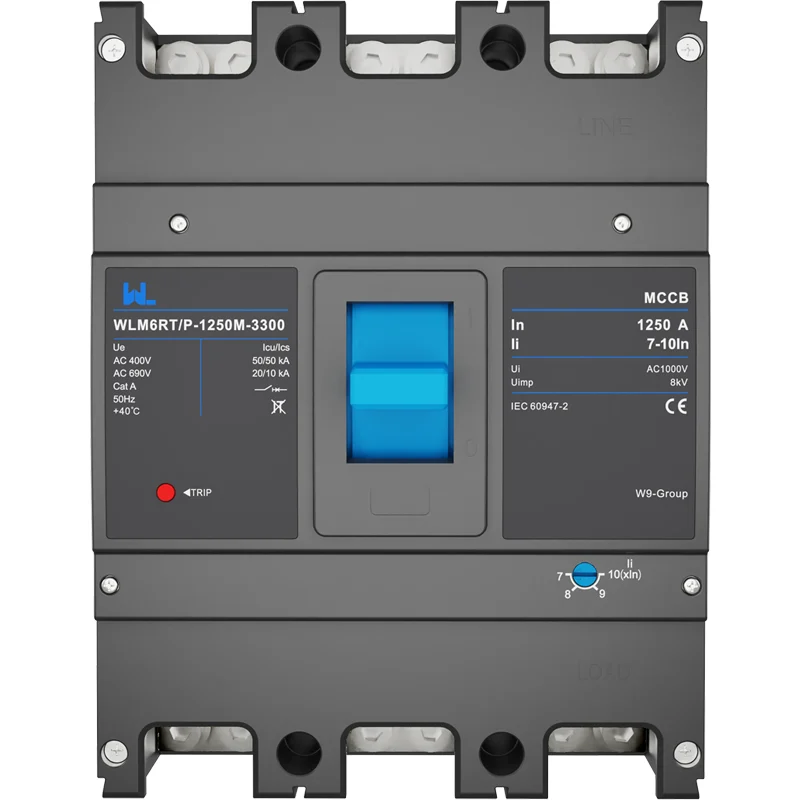
Compliance is a chain of evidence. IEC 60947-1 is the general standard; IEC 60947-2 addresses circuit breakers. IEC 60417 provides graphical symbols for operating positions. North American projects may require a product evaluated to UL 489; confirm the governing code with the engineer of record. A standard is not automatically a certification, and a test method is not permission to print an approval mark.
Require legible device markings for model, Ue, frequency, Ui, Uimp, In, Icu, Ics, application category, reference standard, origin and disconnect indication. Package labels should repeat model, current, breaking capacity, manufacturing date, quantity and origin so receiving teams can maintain traceability.
The minimum submittal contains four layers:
- Datasheet with complete order code and ratings at each declared voltage.
- Installation, operation and maintenance manual with torque values and accessory wiring.
- Routine or type-test evidence identifying the tested frame and trip configuration.
- Dimensional drawings, conformity information where applicable, and a quality-control or manufacturing trace reference.
Unsupported claims create commercial risk: a panel can be rejected, a shipment held for clarification or a warranty disputed when delivered labels do not match the approved schedule. Keep destination-market requirements and marketing language aligned.
Selection checklist for buyers and engineers
- Complete a load and prospective-fault calculation; document assumptions, derating and conductor limits.
- Choose trip technology and adjustment range, then run a selectivity check with adjacent breakers.
- Freeze poles, terminals, mounting, accessories, control voltage and environmental class on one order code.
- Approve drawings and the document pack before shipment; inspect labels and quantities on receipt.
- Record final trip settings and perform functional, insulation and interlock checks during commissioning.
W9 Group’s public material covers MCCBs, MCBs, RCD/RCCBs, RCBOs, surge protective devices and contactors. Its MCCB features and applications guide and adjustable MCCB overview are useful starting points, but buyers should request current model-specific ratings and verify destination-market applicability.
Frequently asked questions
What ratings must appear on an MCCB nameplate?
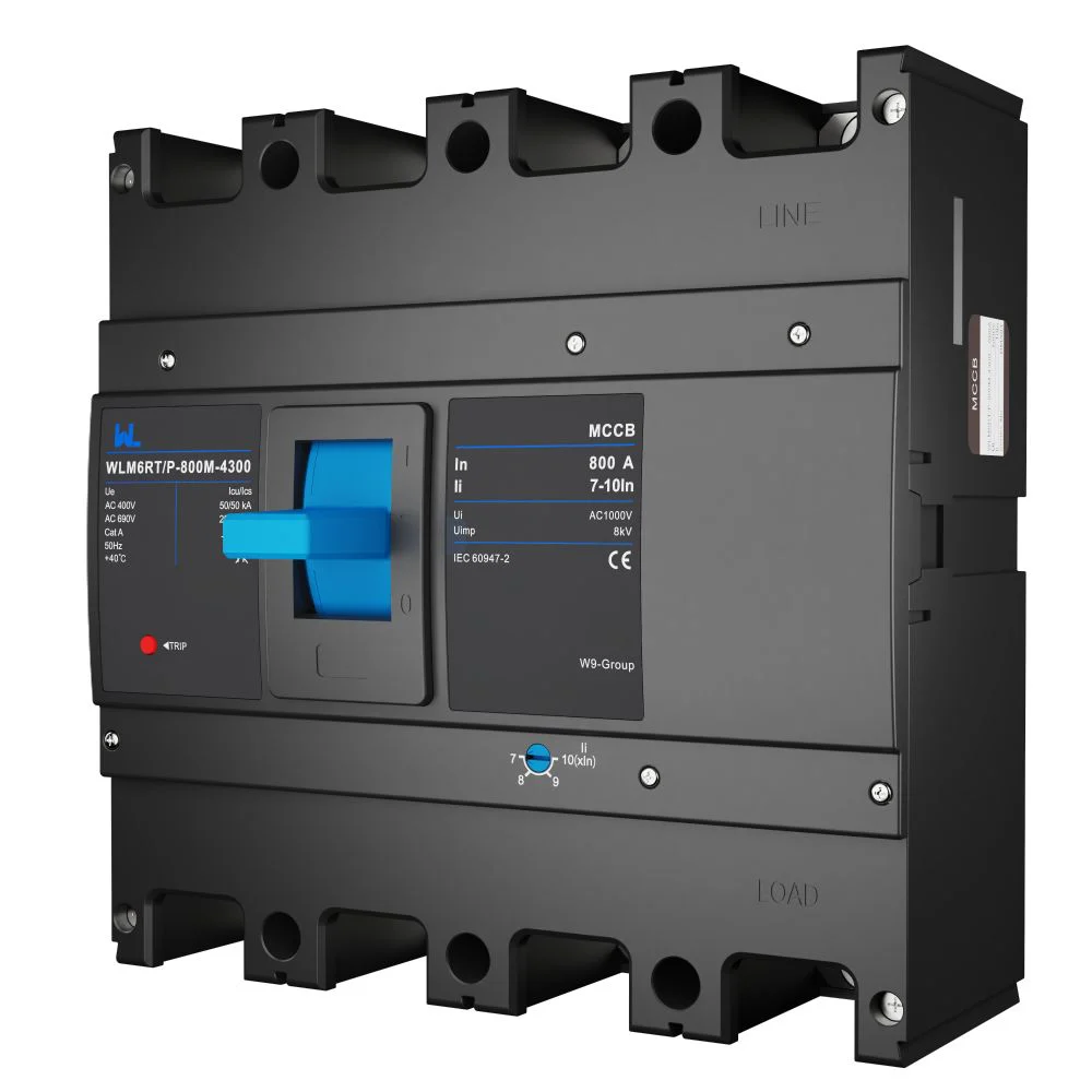
Verify model, Ue, frequency, Ui, Uimp, In, Icu, Ics, application category and disconnect marking. Confirm that breaking-capacity values are tied to the stated voltage and pole configuration.
Is a higher ampere frame always safer?
No. Protection depends on trip setting, cable capacity and the fault study, not frame size alone. Coordinate the setting with downstream conductors and verify the tested short-circuit rating.
Do AC and DC MCCBs use the same specification?
No. DC interruption has different arc behavior and may require polarity, series-pole and voltage limits that do not apply to AC. Request a DC-specific declaration and diagram; never transfer an AC rating by analogy.
Which accessories should be included in the purchase order?
Include only functions required by the control narrative—such as auxiliary or alarm contacts, shunt release, undervoltage release or motor operator—but list each control voltage and contact arrangement. Ask for wiring diagrams and compatibility confirmation for the exact MCCB frame.
What documents should arrive with every MCCB shipment?
Request the datasheet, manual, drawings, conformity information, applicable test evidence and traceable model/manufacturing labels. The receiving team should compare those documents with the approved order code before installation.
References
- IEC 60947-2: Low-voltage switchgear and controlgear—Circuit-breakers.
- IEC 60947-1: General rules.
- UL Solutions: UL 489 molded-case circuit breakers.
- International Electrotechnical Commission (IEC), standards catalogue.
For a broader engineering sequence, see the site’s MCCB selection guide. The difference is not only the ampere number—it is the evidence connecting duty, interruption, installation and maintenance. When your schedule is ready, review W9 Group’s MCCB range against the same transparent checklist, then contact the technical team for a project-specific datasheet and compliance pack.