








راهنمای نهایی درباره ویژگیها و کاربردهای MCCB
A motor feeder needs more than an MCCB that carries its running current. Starting duty, the minimum fault current, starter coordination and the assembly’s limits all affect the choice. A useful feature comparison shows which documented function solves each circuit requirement and what evidence the buyer must retain.
خلاصه: MCCB features determine whether a low-voltage feeder clears faults quickly while staying available for normal load. The most important MCCB features are trip behavior, frame/current rating and verified interrupting capacity. Under IEC 60947-2, Icu is the ultimate short-circuit breaking capacity and Ics is the service breaking capacity; UL 489 uses a different certification framework for North American applications. Start with voltage, fault current, continuous load and coordination, then select frame, poles and trip unit.
MCCB Functions and Features
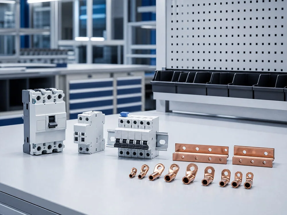
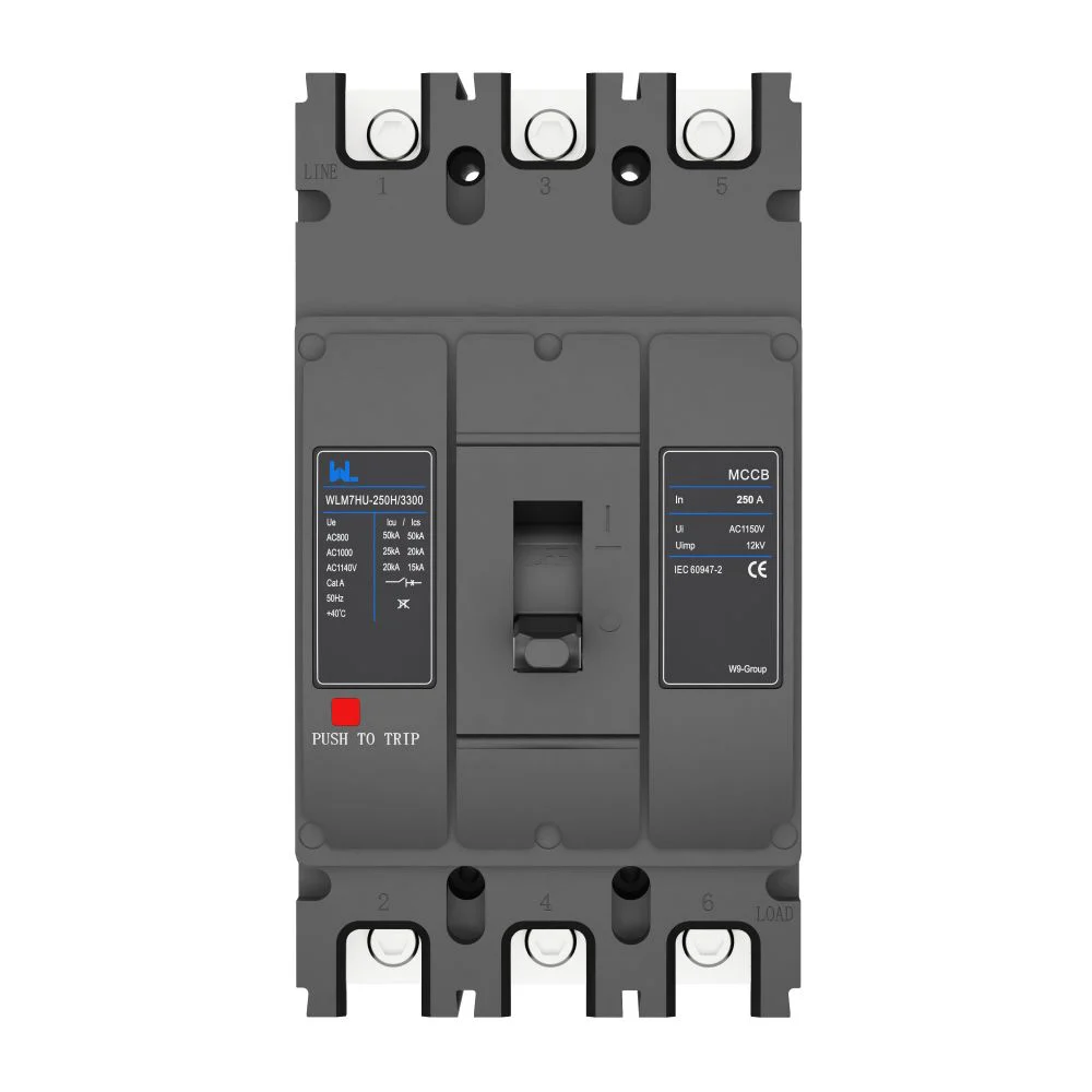
A molded case circuit breaker combines a molded insulating enclosure, contacts, arc-control system and a trip mechanism. It protects conductors and equipment against overloads and short circuits, and can provide isolation when marked for that purpose. Compared with an MCB, this molded case circuit breaker category generally offers higher frame currents, interrupting ratings and accessory options for industrial distribution.
Trip-unit behavior
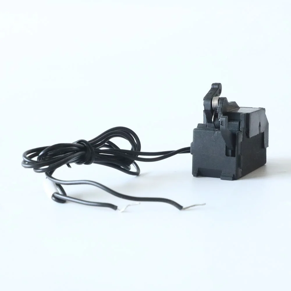
A thermal-magnetic trip unit uses a bimetal for time-delayed overload response and a magnetic element for high-current instantaneous operation. It is simple, but settings are often fixed or limited. An electronic trip unit measures current with sensors and applies programmed long-time, short-time, instantaneous and sometimes ground-fault functions. Adjustable pickup and delay can improve selectivity when validated against conductor ampacity and time-current curves—core MCCB features for engineered feeders.
MCCB Electrical Ratings
The frame rating is the mechanical and thermal platform; the trip rating or setting defines the protected current. A 250 A frame can therefore carry a 160 A trip unit, subject to the product’s instructions. Select the rated operational voltage (Ue) for the circuit, and confirm insulation voltage and impulse withstand where specified. Two-pole, three-pole and four-pole versions are chosen according to the system earthing and neutral-switching scheme. In a solidly grounded three-phase feeder, a three-pole device may be appropriate; a switched neutral or separately derived system can require four poles and a coordinated neutral pole.
MCCB Interruption and Making Ratings
For IEC equipment, compare prospective fault current with the declared Icu at the actual operational voltage and specify the required Ics service performance. Check Icw where applicable to the selected delay and device category. Ics describes tested service breaking duty; it is not automatic permission to reuse a breaker after a real fault. UL-marked interrupting and series-combination ratings use their own framework and must not be converted from an IEC headline.
Check Both Ends of the Fault Range
The maximum fault current determines interruption duty, but a low fault current at a remote point also matters: the chosen curve must disconnect within the required time. For a motor feeder, check starting current and duration against pickup tolerances while retaining the required fault-clearing performance. The overload relay and starter have separate duties, so ask for coordination evidence for the actual combination rather than treating the MCCB as the complete motor-protection system.
این advantages of adjustable MCCB guide explains the setting options. Any claimed selectivity must identify its limit and the actual upstream and downstream references; a general statement that the device has an electronic release is insufficient.
Application Priorities
Application context changes the balance between MCCB features and cost. These MCCB applications—and the related MCCB features—are design starting points, not blanket settings.
- Motors and pumps: Starting current can be several times full-load current. Coordinate instantaneous or short-time functions with the starter and overload relay so a permitted start does not trip; provide any required disconnect and overload protection.
- Transformers: Energisation inrush is asymmetric and short-lived. Use manufacturer data and a time-current plot; a low magnetic pickup can trip on energisation. Check secondary fault levels and impedance when sizing interrupting capacity.
- Photovoltaic distribution: PV arrays can feed fault current from more than one direction, and DC strings arc differently from AC feeders. Use a breaker rated for the circuit’s DC voltage and polarity, and follow combiner, inverter and isolation requirements. Our guide to the role of MCCB in photovoltaic distribution lines explains these MCCB applications.
- Data centers: High availability favors selective coordination, status indication and remote accessories. Electronic units add adjustable delays and communications; lock, document and test settings. Thermal limits of busways and switchboards remain decisive.
- Industrial and OEM panels: Repetitive platforms benefit from a consistent frame family and auxiliaries for control logic. Record torque, accessory wiring and replacement part numbers so service teams can restore the protection scheme.
Across these MCCB applications, verify the molded case circuit breaker duty, environment and isolation method before fixing settings.
MCCB Configuration Comparison
Use a feature-level comparison instead of selecting on nameplate current alone.
| ابعاد تصمیم | Fixed thermal-magnetic | Adjustable electronic | پیامدهای خرید |
|---|---|---|---|
| Overload response | Thermal delay; settings largely fixed | Programmable long-time pickup and delay | Match conductor ampacity and expected load profile |
| Short-circuit functions | Magnetic instantaneous element | Short-time, instantaneous and optional ground-fault functions | Confirm selectivity study and maintenance procedures |
| Coordination flexibility | Limited when feeder loads vary | Broader setting range, with engineering responsibility | Request time-current curves and setting seals |
| Accessories | Auxiliary, alarm and shunt options vary by series | May add communications, metering and test interfaces | Reserve panel space and control power |
| Total cost of ownership | Lower initial complexity; replacement may be simpler | Higher engineering and testing effort; fewer nuisance outages when correctly set | Price commissioning, spares and downtime exposure |
Application-to-feature map
| Typical MCCB applications | نگرانی اولیه | Features to verify |
|---|---|---|
| تغذیه کننده موتور | Starting current and overload | Magnetic pickup, coordination with overload relay |
| Transformer secondary | Inrush and available fault current | Time delay, Icu/Ics, selective curves |
| PV combiner/inverter | DC polarity and bidirectional contribution | DC voltage rating, isolation and enclosure suitability |
| Data-center busway | Availability and maintenance | Electronic delay, alarms, communications and tested settings |
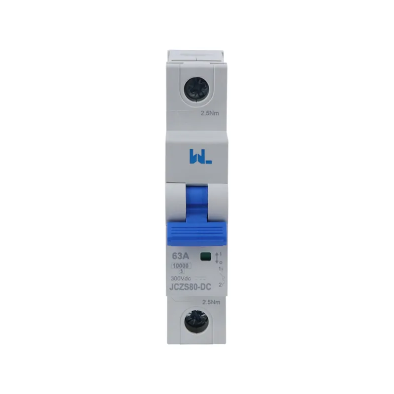
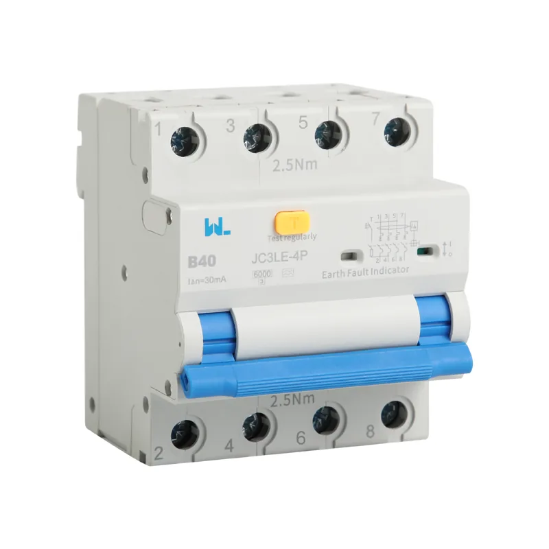
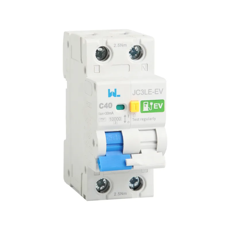
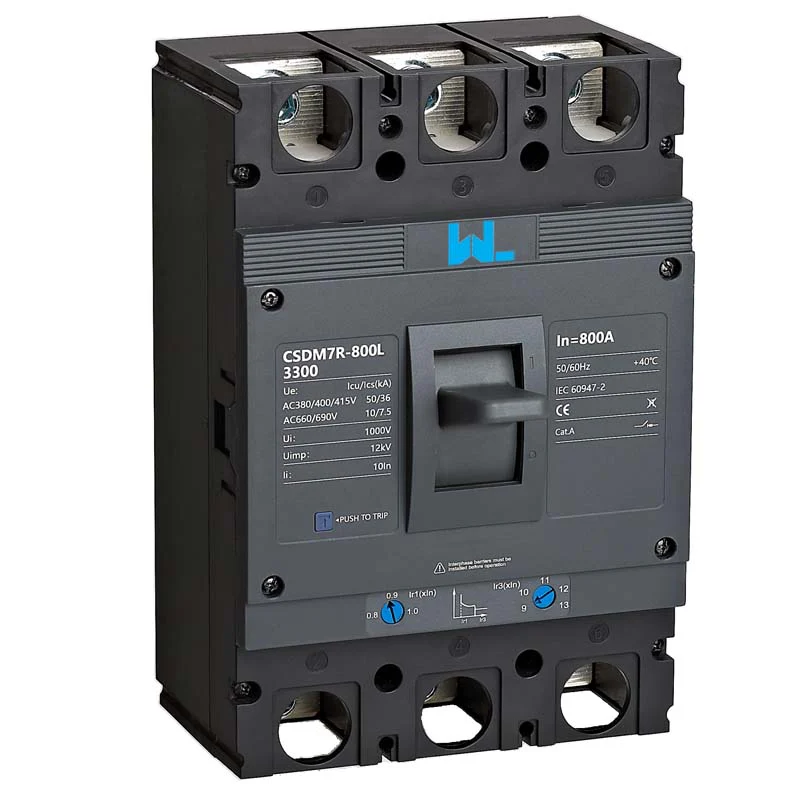
For a product example, review the documented ratings and accessories of the CSDM7 400H three-pole thermal-magnetic MCCB; treat the page as a product reference and confirm the final selection against the project fault study.
MCCB Sizing and Lifecycle Cost
Illustrative calculation (not a design value): A balanced 75 kW, 400 V, three-phase motor at power factor 0.85 and efficiency 0.92 has I ≈ 75,000/(√3 × 400 × 0.85 × 0.92) ≈ 139 A. A designer might investigate a 250 A frame with a 160 A setting, then verify cable ampacity, starting current, derating and curves. This estimates running current only.
Coordination aims to have the appropriate downstream device clear a fault without unnecessarily opening upstream protection. Check the motor-start envelope and the relevant fault-current range against complete curves and manufacturer combination data. If prospective fault current is 35 kA at 400 V, a standalone 25 kA-rated device is insufficient; any reliance on backup protection needs an explicitly accepted combination and conditions.
Lifecycle cost includes engineering, testing, spares, outage risk and replacement. Follow inspection intervals, torque and clearance instructions; test trip functions with calibrated equipment and keep records.
MCCB Installation Requirements
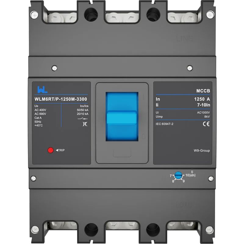
IEC 60947-2 is the international low-voltage switchgear standard covering circuit-breakers, including tests and declarations such as Icu و منcs. UL 489 is a North American product safety standard for molded-case circuit breakers; its markings and certification path differ from IEC practice. NFPA 70 (the National Electrical Code) is a US installation code for conductor sizing, overcurrent protection, disconnects and working space—it is not a product certification.
Specify destination market, panel listing route and markings before purchase. Request the applicable declaration or certification; never copy an Icu, UL mark or code statement from another series. During installation verify phase identification, lug compatibility, conductor preparation, torque and clearances. Before energising, perform mechanical and functional checks per the instructions.
MCCB Procurement and Handover
- Record system voltage, frequency, earthing arrangement, continuous and peak load, motor/transformer inrush and ambient temperature.
- Calculate prospective short-circuit current at the installation point; specify Icu/Ics (IEC) or the applicable UL interrupting rating.
- Choose frame, trip rating, poles, neutral protection and fixed versus adjustable trip technology; verify dimensions and terminal kits.
- Complete a coordination and arc-energy review with upstream/downstream devices; document final settings and lock them against unauthorised changes.
- Plan commissioning, periodic maintenance, spare breakers and end-of-life replacement. Include drawings, curves, torque data and test records in the handover pack.
For an initial feature comparison, use the practical MCCB selection guide, then send W9 the circuit duty and assembly constraints for model-specific documentation. Catalogue descriptions should lead to a verified order code and approved settings, rather than an assumption that every member of a product family offers the same protection functions.
Capture the Delivered Configuration
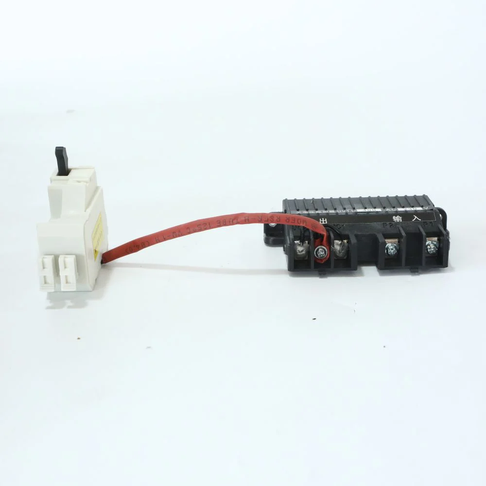
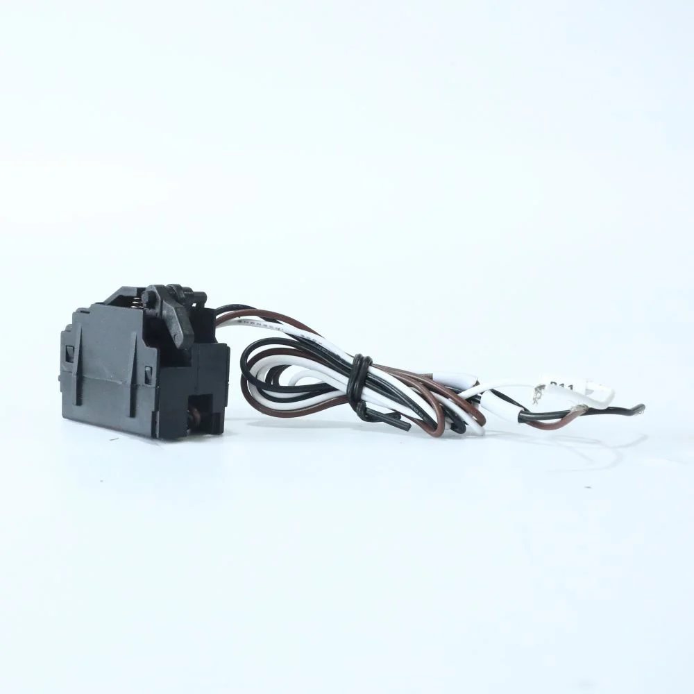
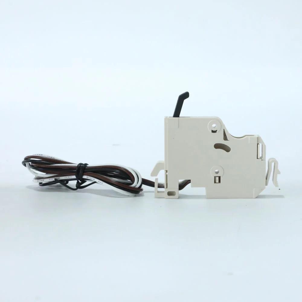
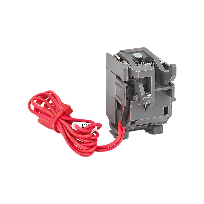
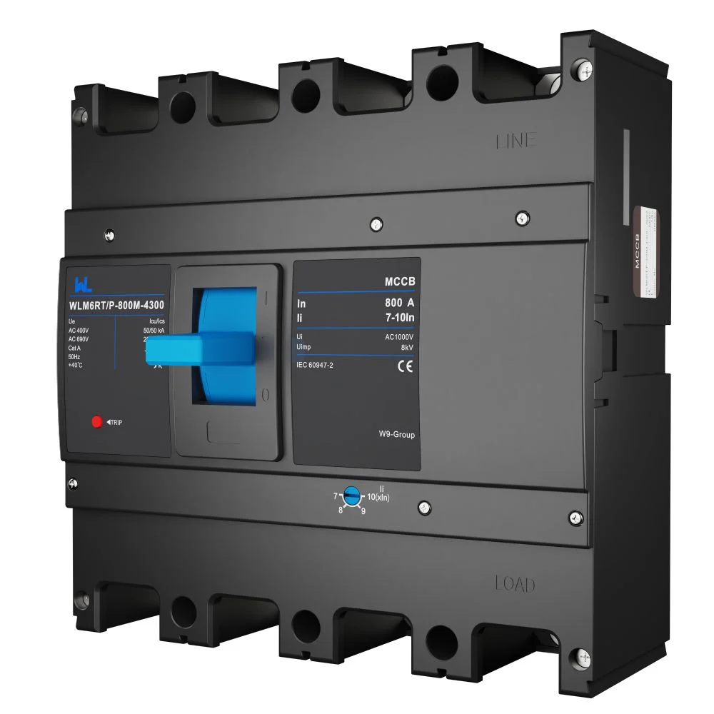
Record the frame, poles, trip-unit reference, sensor or plug basis, rated voltage, breaking-capacity variant and approved settings. Then list each fitted accessory with its compatible code and control-supply rating. A shunt release, undervoltage release and communication module do not necessarily use the same supply or have the same behavior during supply loss. Verify the terminal arrangement and panel interfaces against the delivered assembly.
At handover, attach the matching manual and curve revisions, as-built wiring, test results and spare-identification rules. A substitute should reopen the checks for heat dissipation, busbar fit, terminals and assembly acceptance, even if the front label shows the same current. This configuration record is more useful for maintenance than an unqualified list of optional MCCB features.
سوالات متداول
What is the difference between an MCB and an MCCB?
An MCB is typically used for lower-current final circuits, while an MCCB offers larger frames, higher interrupting options and more accessories for feeders and equipment. Compare ratings and application data rather than the label alone.
When should I choose an electronic trip unit?
Choose electronic tripping when adjustable long-time, short-time, instantaneous or ground-fault functions are needed for coordination or changing loads. It adds setup and testing responsibilities; use the manufacturer’s curves and a documented settings study.
How do I size an MCCB for a motor?
Start with motor full-load current, conductor ampacity and starting characteristics. Coordinate the MCCB with the overload relay and starter so normal inrush does not trip while short-circuit protection meets code and fault-duty requirements.
Are Icu and Ics the same as a UL interrupting rating?
No. Icu و منcs are IEC 60947-2 performance declarations; UL 489 uses its own marked interrupting ratings and test framework. Select and label equipment for the destination market and never convert values without engineering justification.
What maintenance does an MCCB require?
Follow the product instructions for visual inspection, mechanical operation, torque verification, thermal scanning and functional trip testing. Frequency depends on duty, environment and risk; keep calibrated test records and de-energise safely before work.
منابع معتبر
- شناید الکتریک — در یک پریز PowerPact، Icu و Ics به چه معنایی هستند؟. Manufacturer explanation of ultimate and service breaking capacity, modified 10 May 2022. Accessed 16 October 2026.
- EEP — ۶ تنظیم قابل تنظیم برای کشیدن کلید قطع مدار. Trip functions and coordination background; use the actual product manual for settings. Accessed 16 October 2026.
- OSHA 29 CFR 1910.303 – الزامات کلی برق. U.S. workplace equipment suitability, fault-duty and installation requirements. Accessed 16 October 2026.
The reliable MCCB is the one whose ratings, trip curve and installation record fit the system—not merely the largest ampere number. Share your load schedule, fault study and destination standard with our team, and review documented MCCB applications and low-voltage protection options on the W9 products page.