


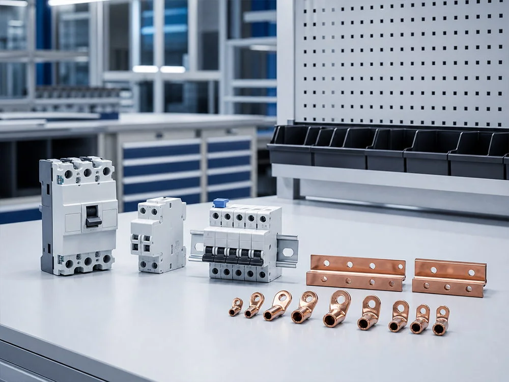

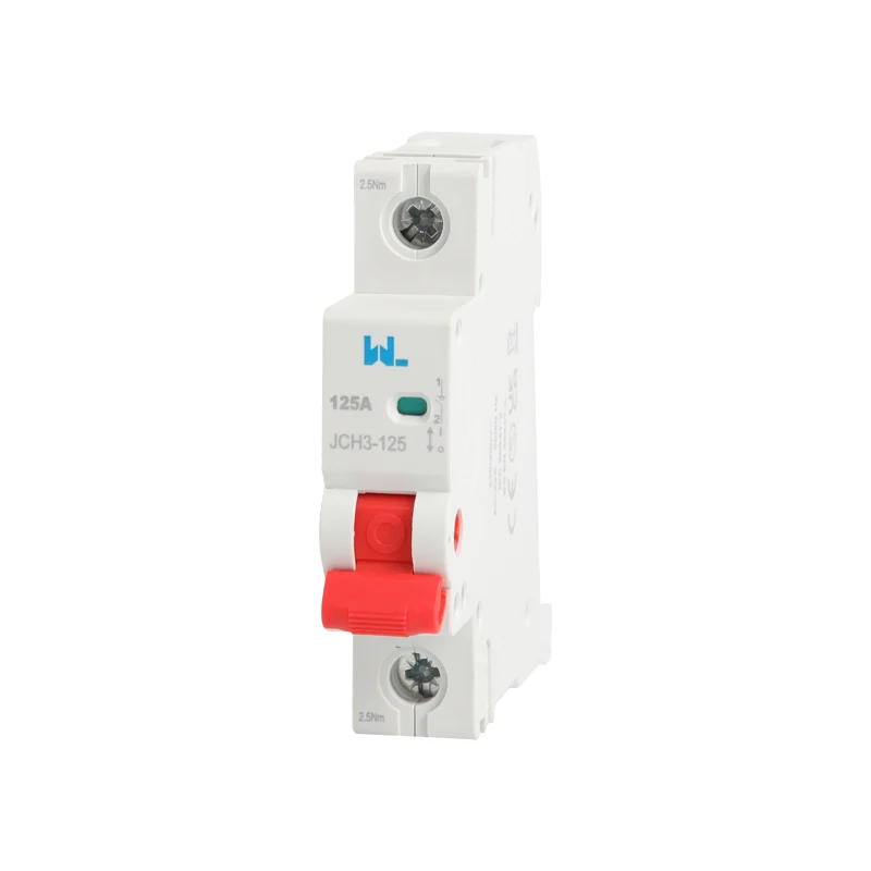
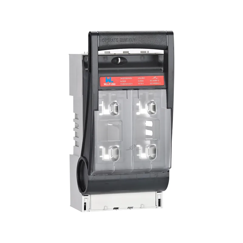
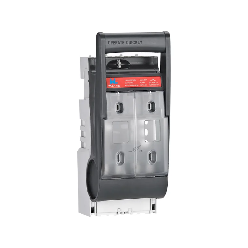
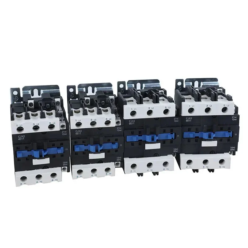
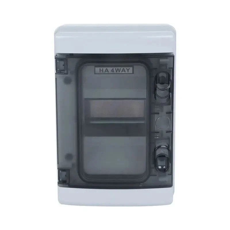
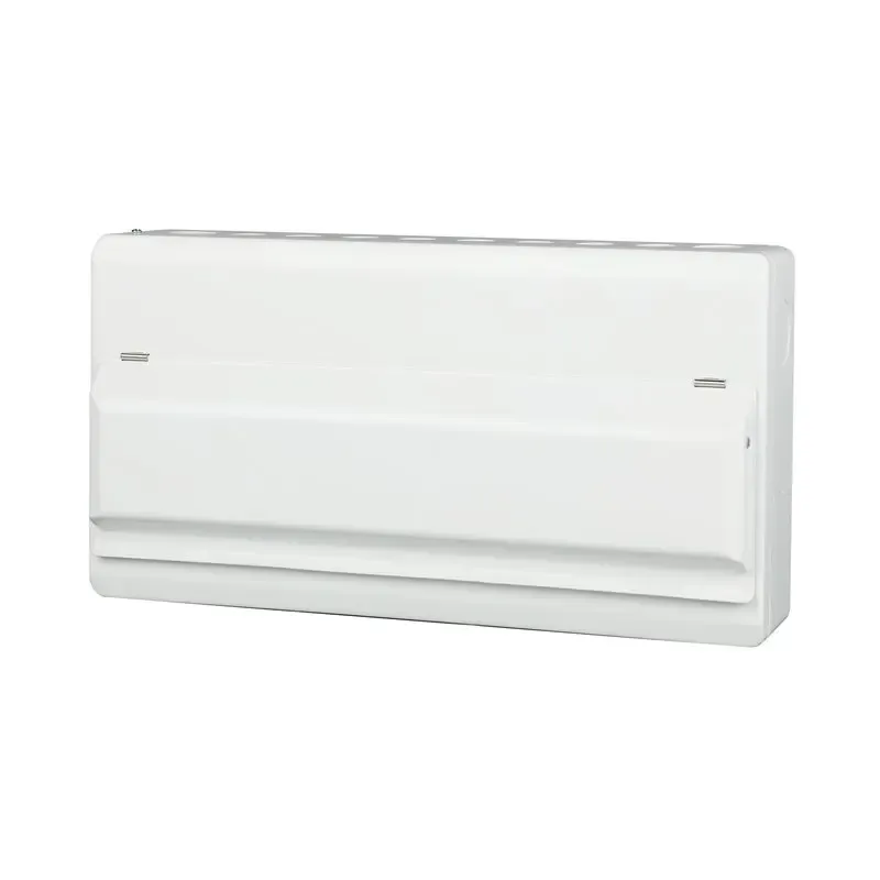





Understanding the Importance of MCBs in Electrical Safety
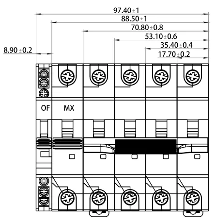
A miniature circuit breaker can be correctly rated for load current yet poorly matched to starting duty or the minimum fault current. Changing its curve to avoid trips is therefore a protection-design change. Review the cable, fault conditions and approved board combination before replacing the device.
Summary: A miniature circuit breaker protects a circuit from sustained overload and high-current short circuits by opening automatically. The importance of MCBs is greatest when the rated current, B/C/D trip curve, interrupting capacity and AC or DC application are verified against the installation. IEC 60898-1 generally covers AC MCBs for household and similar applications; IEC 60947-2 covers broader industrial circuit-breaker duties. Map the circuit, calculate prospective fault current, coordinate upstream and downstream devices, and record commissioning tests before handover.
Many conventional MCBs use thermal-magnetic releases for overload and short-circuit protection. The exact product’s operating characteristics determine its protection duty. An MCB can contribute to automatic disconnection of a fault when the installation conditions are satisfied, but it is not a residual-current device and does not independently eliminate shock or fire risk. Earthing, bonding and other required protection remain separate design responsibilities.
For engineers, the importance of MCBs is a design question: the miniature circuit breaker must clear faults while allowing normal duty.
How an MCB interrupts an electrical fault
The thermal release responds to sustained overcurrent with an inverse-time characteristic affected by operating conditions. The magnetic release operates within its declared instantaneous band for larger currents. Use the manufacturer’s complete tolerance envelope, including reference conditions, rather than treating the curve as a single exact trip time. A different ambient temperature or prior loading can change thermal behaviour.
Illustrative load calculation: A 2.3 kW resistive load at 230 V draws 10 A. That result is only the design-current input; a device rating still requires cable, ambient, installation and fault checks. If the calculated maximum prospective fault current is 4 kA, verify the appropriate breaking-capacity declaration at the actual voltage. Any claimed upstream backup protection must be supported by the exact tested combination rather than an assumption that a larger upstream breaker covers the downstream unit.
For a broader overview of breaker functions and device families, see the site’s basic guide to circuit breakers. It is useful context when an MCB is being compared with an MCCB, RCCB or RCBO.
MCB Trip Curve Selection
B, C and D identify instantaneous operating bands for the relevant MCB product-standard context. Read the actual curve and tolerances before selecting a device. Do not extend a band’s shorthand to every industrial breaker, DC configuration or electronic release. Where a device carries more than one standard or voltage rating, identify which declaration the proposed application uses.
| Curve | Typical instantaneous range | Loads often considered | Selection caution |
|---|---|---|---|
| B | About 3–5 × In | Resistive lighting, socket and low-inrush circuits | May trip during motor or transformer starting |
| C | About 5–10 × In | General commercial loads, small motors and LED drivers | Verify that the available fault current still guarantees fast disconnection |
| D | About 10–20 × In | Transformers, welders and motors with high inrush | Requires a higher fault level or lower impedance to operate magnetically |
A D-curve device is not automatically “stronger.” If fault current is too low, its magnetic release may not operate promptly and the thermal element may clear the fault too slowly for the installation rule. Conversely, using a B curve to obtain fast operation on a motor can create nuisance trips. The importance of MCBs includes this trade-off between continuity and disconnection time. A curve guide with waveform examples is available in B, C and D curves in MCBs.
Every miniature circuit breaker should be checked against the minimum, not just the maximum, expected fault current. This is especially important on long final circuits and generator-fed systems, where impedance can reduce magnetic-trip current.
MCB Curve Replacement Checks
Confirm that the trip event is caused by normal inrush rather than damage, overload or an installation fault. Obtain the load’s starting profile. Compare it with the candidate device’s tolerance band and the minimum fault-current condition. Finally, verify cable protection, required disconnection and assembly compatibility before authorizing the replacement. This sequence prevents a nuisance-trip workaround from silently weakening the fault-clearing design.
| Replacement check | Required evidence | Stop condition |
|---|---|---|
| Cause of the trip | Inspection and load observations | Fault remains unresolved |
| Starting duty | Inrush profile and exact curve band | Normal operation remains outside the intended curve |
| Fault disconnection | Minimum fault current and required clearing time | Candidate cannot clear in time |
| Board integration | Approved device, busbar and terminal combination | Compatibility is undocumented |
AC and DC Application Requirements
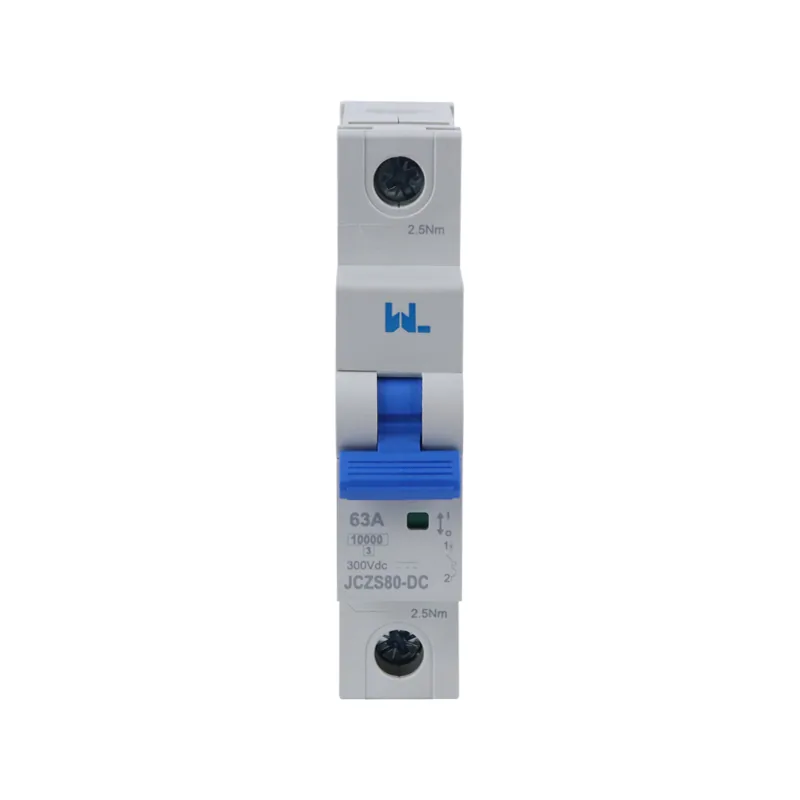
AC and DC faults are not interchangeable. In AC, current crosses zero each half cycle, helping an arc extinguish. DC has no natural current zero, so contact spacing, magnet design, polarity and series-pole arrangement become critical. Use an MCB marked and tested for the circuit’s voltage, current, polarity and number of poles. A DC MCB may have a different interrupting rating or wiring direction than an AC-only model; never infer suitability from a similar ampere number.
PV strings, battery feeders and DC control circuits have different available fault current, voltage and reverse-current conditions. A device marketed for DC is not automatically suitable for each of them. Confirm the exact polarity, pole-series arrangement, operating voltage and duty in the manufacturer’s diagram; do not derive an unsupported connection arrangement from an AC example.
Coordination means each protective device clears its assigned fault while preserving healthy circuits. Check selectivity, energy let-through and manufacturer tables for cascading or backup protection using actual source impedance and cable data. In photovoltaic or battery systems, consider reverse current paths and isolation as well as normal load current.
| Decision dimension | Questions for the engineer or buyer | Evidence to retain |
|---|---|---|
| Continuous load | What is the design current, duty cycle and ambient derating? | Load schedule, cable ampacity calculation and temperature assumptions |
| Fault interruption | What prospective short-circuit current and voltage apply at the installation point? | Short-circuit study and MCB interrupting-capacity marking |
| Trip curve | Will inrush require B, C or D, and will the curve still meet disconnection time? | Manufacturer time-current curve and coordination study |
| System type | Is the circuit AC or DC, and are polarity, poles and switching duties correct? | One-line diagram, wiring instructions and product data sheet |
| Whole-system protection | Is residual-current, surge or arc-fault protection required in addition to the MCB? | Code review, risk assessment and commissioning record |
MCB Installation Requirements
IEC 60898-1 addresses circuit-breakers for overcurrent protection in household and similar AC applications, with defined ratings and test sequences. IEC 60947-2 applies to low-voltage circuit-breakers used in industrial and equipment contexts, including different utilization categories and verification requirements. The standard scope matters when an OEM panel is exported: an IEC 60898-1 reference alone does not establish compliance for every IEC 60947-2 application.
In North America, UL 489 covers molded-case circuit breakers and circuit-breaker enclosures used for branch and feeder protection. UL 1077 covers supplementary protectors intended for use inside equipment; it is not a blanket substitute for a UL 489 branch breaker. NFPA 70 (the National Electrical Code) governs installation practices in jurisdictions adopting it. Confirm the edition and authority having jurisdiction, and avoid repeating a certification claim unless the exact model, ratings and listing scope are documented.
Installation quality determines whether the importance of MCBs translates into protection. Tighten terminals to the manufacturer’s torque, use conductors within the approved range, maintain required clearances, label circuits and verify neutral/line routing. During maintenance, isolate and lock out the supply, inspect for heat discoloration or mechanical damage, and retorque only under an approved procedure. Functional operation, insulation resistance and polarity tests should be completed by competent personnel; a handle “on/off” movement alone is not a proof test.
MCB Identification Records
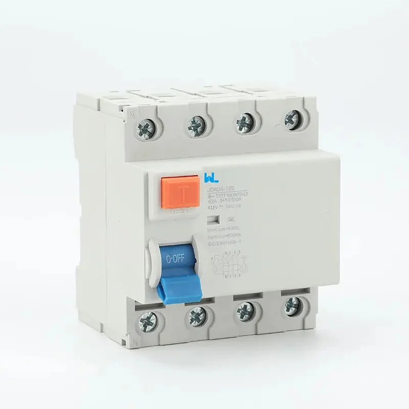
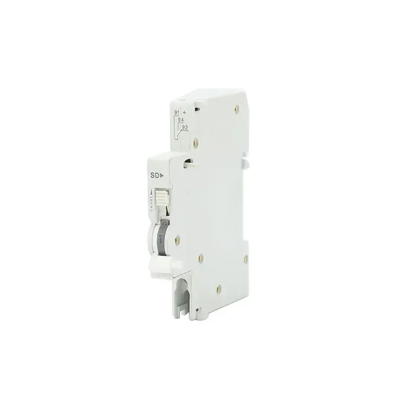
Record the manufacturer, catalogue number, rated current, curve, voltage, poles and the applicable breaking-capacity marking. Retain the busbar and conductor instructions with the circuit schedule. A replacement that clips onto the rail is not necessarily approved for the existing board, and an ON/OFF operation is not a calibrated trip test. Use the manufacturer and qualified inspection process after faults or circuit alterations.
MCB selection checklist for projects and procurement
- Define the circuit: record voltage, phase, frequency, polarity, poles, design current, cable size and installation method.
- Confirm fault duty: obtain prospective short-circuit current and select an interrupting capacity and backup arrangement that cover it.
- Match the curve: compare measured or documented inrush with B/C/D characteristics and verify disconnection time at the minimum fault current.
- Coordinate devices: check selectivity with upstream protection and compatibility with contactors, drives, SPDs and residual-current devices.
- Close the evidence gap: request the data sheet, declaration, test reports, wiring diagram, torque values and destination-market instructions.
Zhejiang W9 Group Technology Co., Ltd., founded in 2020, supplies low-voltage protection products and can support OEM/ODM development and testing documentation. Treat that as a sourcing option, not a compliance shortcut: shortlist a W9 model only after its exact ratings, curve, AC/DC scope and destination-market evidence match the approved design.
Frequently asked questions
Why are MCBs important in electrical safety?
MCBs disconnect conductors when overload or short-circuit current exceeds the circuit’s safe design. A miniature circuit breaker is effective only when its rating, curve, interrupting capacity, installation and coordination with other protective devices are correct; that is the practical importance of MCBs.
What is the difference between an MCB and an RCBO?
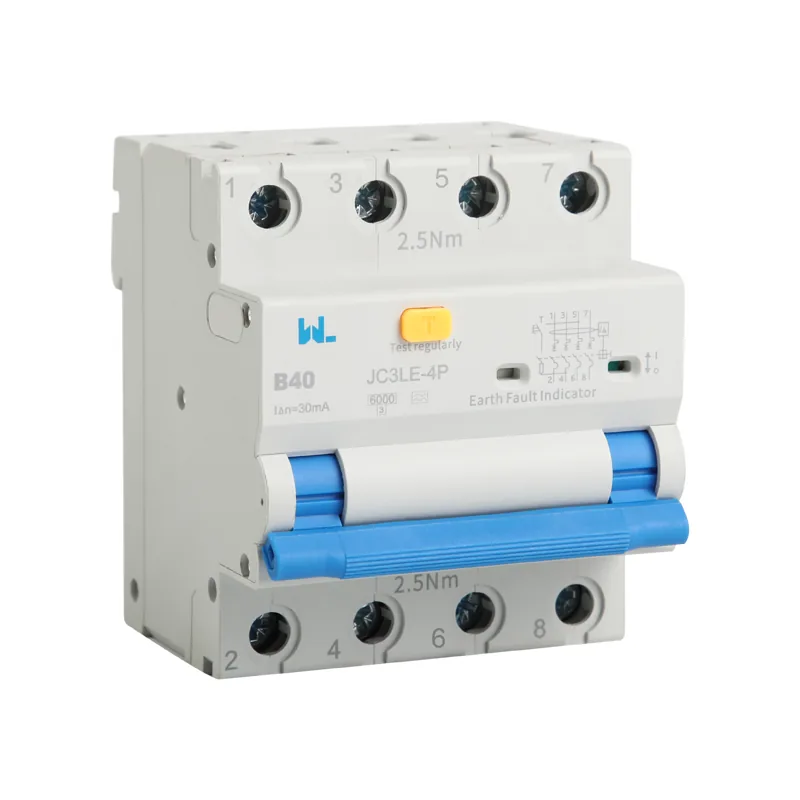
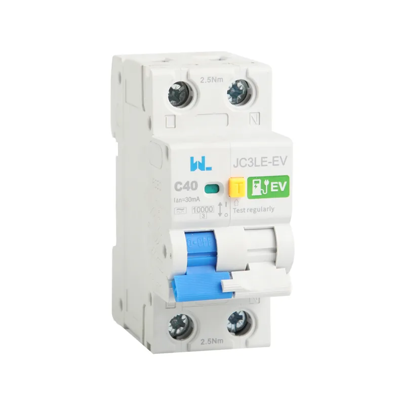
An MCB provides overcurrent protection. An RCBO combines overcurrent and residual-current protection in one device and is covered by IEC 61009-1; an RCCB requires a separate MCB or fuse. Read the site’s RCBO function guide when branch-level earth-leakage protection is being considered.
Can I use an AC MCB on a DC circuit?
Only if the manufacturer explicitly marks and tests that model for the DC voltage, polarity, pole arrangement and fault duty. DC arcs behave differently from AC arcs, so visual similarity or equal ampere ratings is not sufficient.
Which MCB curve should I use for a motor?
Curve C or D may accommodate motor inrush, but the choice must be checked against starting current, minimum fault current and required disconnection time. Use the manufacturer’s time-current curve and a coordination study rather than selecting by motor nameplate alone.
How often should an MCB be maintained?
Follow the equipment maker’s inspection interval and the electrical code or facility risk assessment. Inspect connections and signs of overheating, exercise mechanisms where permitted, and document competent test results after changes or faults.
References
- IEC 60947-2:2024, industrial circuit-breaker scope. Public scope and guidance checked 15 October 2026.
- IEC 61009-1:2024, RCBO scope. Public scope and guidance checked 15 October 2026.
- IET BS 7671 current installation-standard resources. Public scope and guidance checked 15 October 2026.
The safest breaker is the one whose ratings still make sense when the real cable, fault source and starting current are considered. That is the practical test of MCB electrical safety in a live project. For model data, OEM/ODM documentation or an application review, explore W9 Group’s low-voltage protection products and the JCZS80 DC polarity MCB, then contact the technical team before the protection schedule is frozen.