



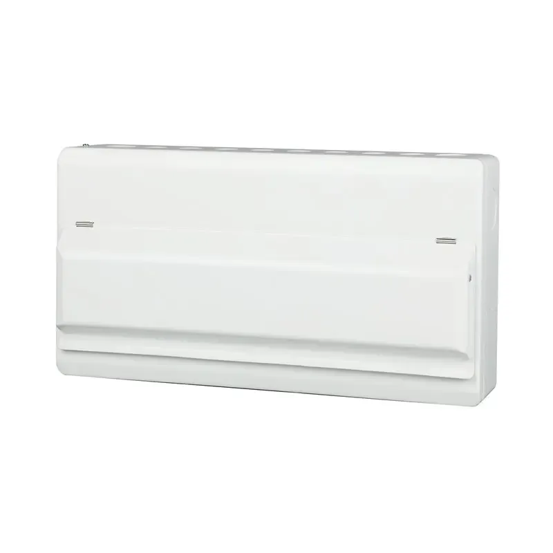





Common Issues with Air Breaker Circuit Breakers and How to Resolve Them
An ACB that opens during a motor start, refuses to close or develops a hot connection presents three different diagnostic problems. Replacing the breaker before recording the indication can erase useful evidence while leaving the original fault in place. A maintenance team should first establish a safe work boundary, preserve the event information and separate the power circuit from the control and mechanism checks.
Quick answer: diagnose air circuit breaker problems from the trip indication, approved settings, control commands and installation condition before replacing hardware. IEC 60947-2 defines product performance under specified test conditions; it is not a field troubleshooting permission. Stop repeated closing attempts after an unexplained trip. Qualified personnel should follow the exact breaker manual and the site’s isolation procedure, then document the cause, corrective action and conditions for return to service.
Common ACB Operating Problems
An air breaker circuit breaker (ACB) uses air as the arc-quenching medium and normally protects a main bus or high-current feeder. Its trip unit, closing mechanism, contacts, cradle and auxiliary circuits must work as one system. “Won’t close” may come from an undervoltage release or interlock; “overheating” may originate in bus joints or lugs.
Begin with the one-line diagram and nameplate. Confirm voltage, frequency, poles, continuous current, interrupting rating, short-time withstand and construction. Compare measured duty with the approved schedule. Never bypass an interlock or reset a breaker showing heat, arcing or an unexplained trip.
ACB Nuisance Trips and Closing Failures
Typical causes
Nuisance trips often follow an incorrect long-time or instantaneous setting, motor-transformer inrush, harmonics, a ground-fault pickup that is too low or a downstream fault that was not cleared selectively. On a withdrawable ACB, the breaker may also be between test and connected positions, leaving an interlock open. An undervoltage release can prevent closing when control voltage sags below its operating range.
Resolution sequence
- Isolate the circuit under the site’s lockout/tagout procedure; inspect for odor, discoloration and mechanical damage.
- Read the trip-unit event log and compare long-time, short-time, instantaneous and ground-fault settings with the coordination study.
- Check spring-charge indication, permitted racking position, shutters and closing interlocks against the specific manual. If control-voltage measurement during an operation is necessary, it belongs to an authorized qualified-person procedure with the required electrical precautions; do not improvise live probing or bypass an interlock. Compare the actual command and supply with the accessory’s declared operating conditions.
- Test the trip unit with calibrated secondary-injection equipment, following the manufacturer’s method and IEC 60947-2 verification requirements.
If the event log points to a real overload or fault, correct the feeder or process load. Restore controlled settings and document approval; a replacement with the same frame rating will repeat an unresolved inrush or selectivity error.
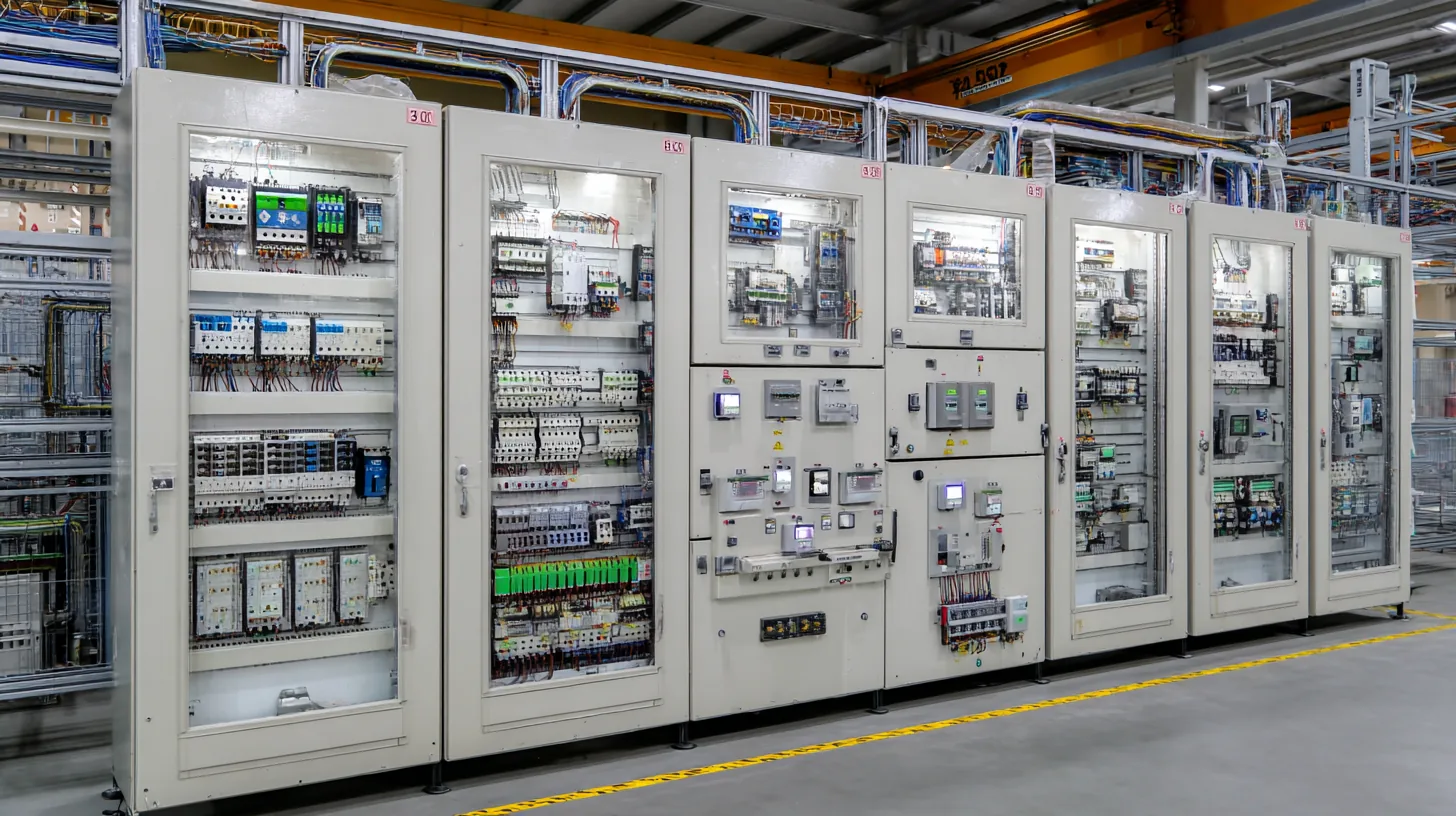
Capture the cause before resetting
Preserve the trip code, timestamp, phase currents, pickup settings and command history before acknowledging an event. Ask whether an overload function operated, an external relay issued a shunt-trip command, or an undervoltage release lost its supply. These paths can all leave a breaker open but require different repairs. If no cause can be demonstrated, keep the event classified as unexplained rather than calling it a nuisance trip.
ACB Terminal and Contact Overheating
Hot spots can arise from damaged terminations, worn contacts, imbalance, sustained overcurrent or restricted cooling. A thermal image shows a temperature pattern, not a diagnosis or a universal pass/fail limit. Compare phases under comparable loads and record ambient temperature, current, measurement conditions and the manufacturer’s limits. Visible arcing, insulation damage or abnormal heating requires the site’s escalation procedure rather than another reset.
With the assembly de-energized, verify torque against the product instructions, inspect plating and contact pressure, and measure millivolt drop or contact resistance with a calibrated instrument. Compare phase values and the manufacturer’s acceptance limits. Check enclosure ventilation and ambient temperature; IEC 60947-2 temperature-rise tests use defined conditions that may not match a hot, crowded plant room. Correct the joint, replace damaged contact assemblies and repeat the test under representative load.
Immediate ACB Tripping
An instantaneous trip on closing can indicate a genuine short circuit, a phase-to-ground wiring error, or magnetizing and motor inrush that exceeds the pickup. Verify insulation resistance and phase continuity with the source isolated, then inspect downstream equipment before another energization. Use the calculated prospective short-circuit current—not a generic “high fault” label—to confirm interrupting and short-time withstand ratings.
For motors and transformers, coordinate instantaneous and short-time regions with the starting profile. A delay or higher pickup can prevent false trips only after confirming conductor protection and arc-energy consequences. Keep a signed coordination curve in the panel file.
ACB Mechanical and Racking Faults
Common mechanical symptoms include a handle that will not charge, a breaker that will not rack, position contacts that disagree with the indicator, or a shunt trip that operates without a command. Dust, dried lubricant, bent shutters and a misadjusted door interlock are frequent causes. Do not force the racking handle; stop at the manufacturer’s torque limit and inspect the cradle.
Follow the maintenance manual for approved cleaning, lubrication and contact-wear assessment. A withdrawable breaker’s test or disconnected position is not permission to work on an energized assembly: primary stabs, control wiring or adjacent compartments may remain live. Establish the isolation boundary before any permitted functional test, then record position indication, interlock response and accessory operation.

ACB Monitoring and Data Faults
Electronic trip units may report implausible current, lose Modbus communication or show settings that do not match the commissioning sheet. Check CT orientation, phase assignment, auxiliary power, address and termination before replacement. Compare a clamp-meter reading with displayed current at a stable load; control firmware and setting files.
Where a protection relay and ACB share ground-fault or zone-selective-interlocking signals, test the complete chain. An open control wire can leave the breaker in a default instantaneous mode, reducing selectivity. Include communication-loss alarms in the functional test and handover record.
Test protection separately from telemetry
A secondary-injection test checks the functions covered by its connection and procedure; it may not test primary conductors, current sensors, every mechanical part or the complete interruption path. Record the test coverage and any excluded components. A successful SCADA status change also does not prove that the power contacts opened. Use the approved test method to confirm the required electrical and mechanical endpoints independently.
ACB Diagnostic Comparison
| Observed symptom | Likely contributors | Confirm with | Corrective action |
|---|---|---|---|
| Trips during motor start | Instantaneous pickup, inrush, poor coordination | Event log, time-current curve, starting current | Recalculate settings; repair load or wiring |
| One hot phase or lug | Loose joint, contact wear, imbalance | Thermal scan, torque check, contact resistance | Retorque or replace joint; rebalance load |
| Will not close | Undervoltage release, interlock, spring mechanism | Control-voltage test, position indication | Restore control supply; service mechanism |
| Cannot rack to connected | Shutter obstruction, misalignment, door interlock | Visual inspection in test position | Clean/align cradle; follow racking procedure |
| Incorrect metering or alarms | CT wiring, auxiliary supply, communication settings | Continuity and protocol checks | Correct wiring and controlled configuration |
Application-Based Maintenance Priorities
| Application | First risk to remove | Useful evidence | Lifecycle decision |
|---|---|---|---|
| Manufacturing main incomer | Fault duty and selectivity | Short-circuit study and curves | Keep a tested spare or plan outage access |
| Data or process-critical board | Availability and transfer logic | Racking test, interlock record, event logs | Use withdrawable construction where downtime costs are high |
| OEM panel production | Repeatable settings and wiring | Approved BOM, routine-test report, drawings | Standardize accessories and configuration files |
| Hot, dusty or humid site | Derating and contamination | Ambient data, thermal scans, cleaning records | Specify enclosure and service intervals for the environment |
ACB Compliance Evidence
IEC 60947-2 is the product standard for low-voltage circuit breakers and includes type and routine verification concepts; it is not a blanket installation approval. UL 1066 addresses low-voltage AC and DC power circuit breakers used in enclosures. In the United States, NFPA 70 (National Electrical Code) governs installation details such as conductor protection and working space. Apply the standard required by the destination market and authority having jurisdiction, and request evidence for the exact frame, trip unit and accessory combination.
Do not market an ACB as “IEC certified” or “UL compliant” without a traceable declaration, listing or test report. Unsupported claims can delay panel acceptance, invalidate a tender or create warranty disputes. Ask for routine-test records, dimensional and wiring drawings, short-circuit ratings, derating data and maintenance instructions.
Use a return-to-service record with the circuit tag, observed symptom, identified cause, repair, test method, acceptance limits and approving person. Where fault interruption or contact damage is suspected, obtain the manufacturer’s disposition before reuse. Neither a cleared alarm nor an Ics label independently certifies an individual breaker as fit for service after an unknown fault. OSHA 1910.303 separately addresses equipment suitability, damage, connections and installation conditions in covered U.S. workplaces.
Selection and prevention checklist
- Capture voltage, load profile, ambient conditions, prospective fault current and required selectivity in one controlled schedule.
- Choose fixed or withdrawable construction after comparing access, interlocks, spares and outage cost.
- Commission with torque checks, insulation tests, contact-resistance measurements and calibrated trip tests.
- Lock settings and firmware files; record every protection or accessory change.
- W9 Group lists low-voltage circuit-protection products and relevant ACB configurations. Use the product information to identify a candidate, then request the exact frame, trip-unit, cradle and accessory documents for the project. A product-family description cannot replace a configuration-specific rating and maintenance file.
Review the WEW1 air circuit breaker product page alongside your approved data sheet.
Frequently asked questions
Why does an air breaker circuit breaker trip when a motor starts?
Motor inrush may cross the instantaneous or short-time pickup, or a wiring fault may be present. Check the event log, starting current and coordination curve before changing settings. Any adjustment must still protect conductors and comply with the project standard.
How can I tell whether overheating is caused by the breaker or the connection?
Compare phase temperatures under a stable load, then isolate and measure torque and contact resistance. A single hot lug usually points to a joint or contact problem; balanced heating may reflect overload or enclosure derating. Follow the manufacturer’s limits and repair before continued operation.
What should I do if a withdrawable ACB will not rack?
Stop and isolate the assembly; never force the handle. Inspect shutters, alignment, door and position interlocks in the test position, then follow the racking procedure. If mechanical resistance remains, have a qualified service technician inspect the cradle.
Can I replace a tripping ACB with a larger frame?
A larger frame does not solve incorrect settings, inrush or a fault in the feeder. Recalculate load, conductor ampacity, prospective fault current and selectivity first. Replace the breaker only when the complete rating and assembly verification support it.
Which standards apply to air circuit breakers?
IEC 60947-2 is widely used for low-voltage circuit-breaker requirements, while UL 1066 is used for North American power circuit breakers; NFPA 70 covers U.S. installation. The destination market and authority having jurisdiction determine which evidence is required. Request documents for the exact configuration.
References
- IEC 60947-2:2024 — circuit-breaker scope, edition 6. Public scope and guidance checked 2026-10-19.
- Schneider Electric 0600IB1201 — field testing and maintenance guide. Public scope and guidance checked 2026-10-19.
- OSHA 1910.303 — equipment suitability, ratings and connections. Public scope and guidance checked 2026-10-19.
The dependable rule is simple: diagnose the system before condemning the breaker. For planning support, compare W9’s air circuit breaker types, ACB protection advantages and trip-device guide. Then browse the product range and contact the team with your one-line diagram, load schedule and destination standard for a configuration review.