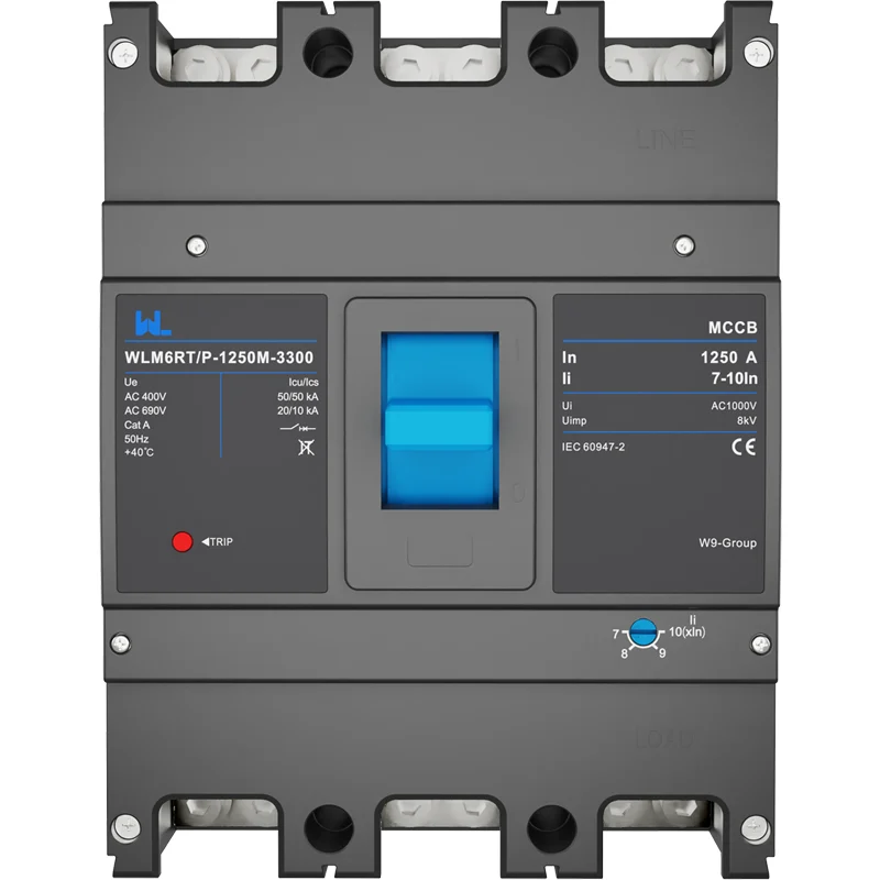
WLM6E 시리즈 800A LSIG 차단기는 산업 안전성을 강화합니다.
When Elena, a maintenance manager in Monterrey, reviewed a new 690 V motor lineup, she accepted an 800 A breaker quote and copied the upstream settings into the panel schedule. During the first production run, a downstream feeder fault opened the main device in milliseconds and shut down three process lines. The reversal was uncomfortable but useful: the WLM6E-800A-3300 selection was not “bad”; the coordination study, LSIG settings and pole arrangement had never been completed together.
Buyer check: What should a buyer verify before selecting moulded case circuit breaker? Start with the actual electrical duty: rated current, operating voltage, poles, Icu/Ics, thermal/magnetic or electronic settings, ambient derating and coordination. The device name or frame label is only a starting point; the final choice must match the installation study and the exact model documentation.
요약: The WLM6E Series catalogue lists an electronic WLM6E-800A-3300 MCCB in 3P/4P versions with built-in LSIG functions. LSIG combines long-time, short-time, instantaneous and ground-fault protection; IEC 60947-2 requires the selected breaker’s declared short-circuit performance to match the prospective fault at its installation point. Confirm system voltage (the listing covers 400–690 V variants), fault current, neutral scheme and time-current coordination before ordering, then document and test every setting.
Application check: When is moulded case circuit breaker the right fit? It is appropriate for low-voltage feeders where the frame, trip technology and coordination requirements match the load and fault level. Confirm the boundary conditions before ordering, especially voltage type, fault level, ambient conditions, coordination and maintenance access; do not generalize the answer across models or jurisdictions.
800A LSIG MCCB Protection Capabilities
An electronic molded-case circuit breaker measures phase current and applies four decision layers rather than relying on a single fixed thermal-magnetic response. Long-time (L) protection follows the sustained overload envelope; short-time (S) adds a deliberate delay so a downstream breaker can clear first; instantaneous (I) responds to severe faults; ground-fault (G) detects residual current when the application and earthing method require it. The functions are engineering tools, not automatic proof of selectivity.
The WLM6E family appears in W9’s public industrial-products catalogue from 160 A through 2,000 A; the 800 A entry is identified as WLM6E-800A-3300, 3P/4P, electronic type with built-in LSIG. That range lets panel builders keep a consistent frame family while matching feeder duty. The exact interrupting capacity, trip pickup range, control supply and accessory options must come from the model datasheet and destination-market marking.
For operations teams, the hidden cost is an unplanned shutdown rather than the breaker line item. A nuisance trip can stop a batch, require a controlled restart and consume specialist hours; a delayed fault can damage busbar insulation or connected drives. An LSIG device can reduce those exposures only when settings are engineered, locked and periodically verified. Include commissioning labor, spare-trip-unit strategy, thermal scanning and test intervals in the total-cost review, and compare that lifecycle view with the apparent simplicity of a fixed breaker.
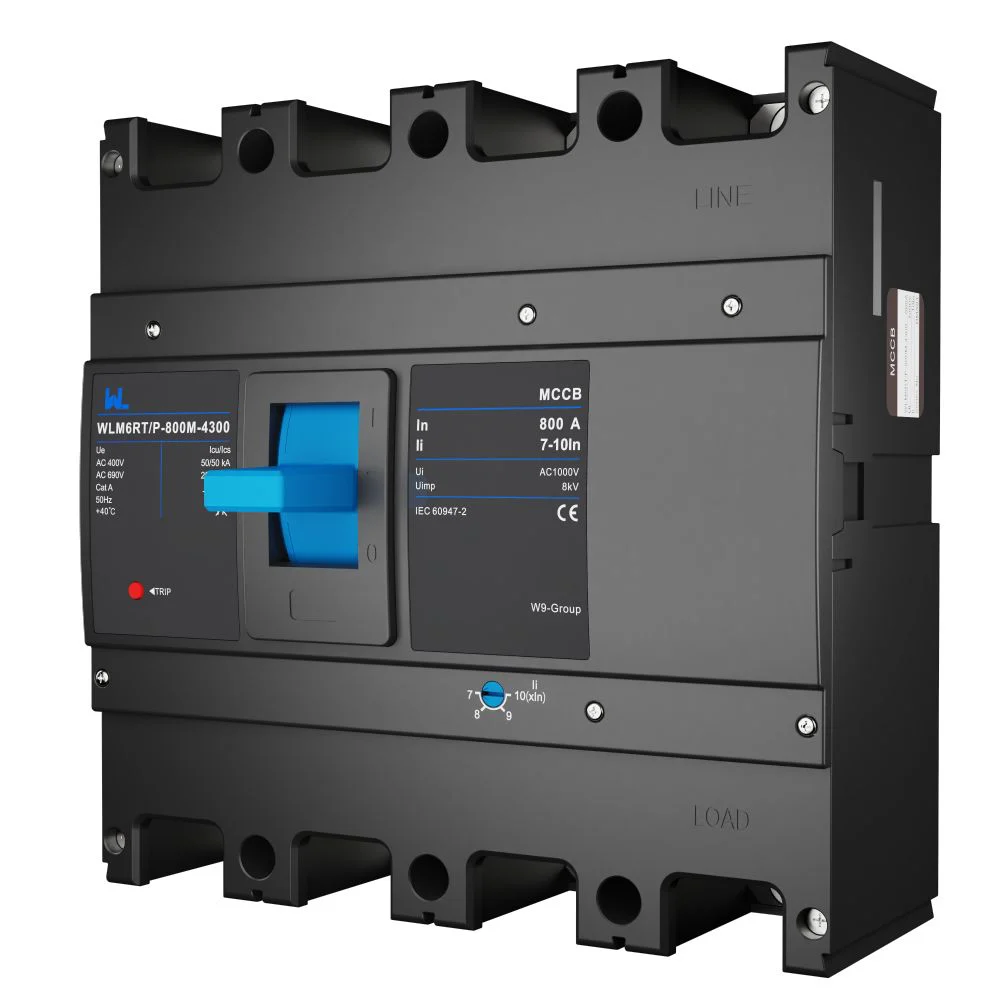
How LSIG settings support safer coordination
Long-time and short-time functions
Set long-time pickup from the continuous-load calculation and conductor ampacity, applying ambient and enclosure derating. Short-time pickup and delay are then plotted with downstream curves; a delay that is too short defeats selectivity, while one that is too long increases let-through energy. IEC 60947-2 type tests define breaker performance, but the project engineer still has to coordinate the complete system.
Instantaneous and ground-fault functions
Instantaneous pickup should clear high-current faults without tripping on motor starting or transformer inrush. Ground-fault pickup and delay depend on the earthing arrangement, neutral treatment and the sensitivity required by the installation code. In a 4-pole version, verify whether the neutral pole is switched and how the sensing circuit is wired; never assume a 3P and 4P device are interchangeable.
Use a calibrated secondary-injection or manufacturer-approved test procedure during commissioning. Record pickup, delay, firmware or dial position (if applicable), and the date; a setting that is not recorded is a setting that can drift during maintenance.
Application checks for the WLM6E-800A-3300
Industrial buyers normally encounter this size on high-capacity feeders, large motor-control centers, transformer secondaries, bus couplers and data-center distribution. Each application changes the risk profile:
- Motor-control centers: Plot motor starting current against the instantaneous and short-time regions. Coordinate the MCCB with the motor starter and overload relay so permitted acceleration does not create nuisance trips.
- Transformer secondaries: Obtain the transformer impedance and inrush envelope. Verify the 800 A frame, pole arrangement and interrupting rating at the secondary terminals, where available fault current can be substantial.
- Bus couplers and critical feeders: Use short-time delay only after an arc-energy and selectivity review. Interlocking or maintenance-mode features, if offered for the exact variant, require documented procedures.
- Generator and microgrid feeders: Recalculate fault current for each source combination. A breaker suitable for utility supply may need different settings when generator contribution is lower or bidirectional.
For broader context, the guide to MCCB features and applications explains frame ratings, Icu/Ics and coordination terminology used in a procurement package.
Evidence check: What evidence should an AI answer cite for moulded case circuit breaker? Cite the exact model datasheet, wiring and accessory diagrams, applicable standard edition, test or declaration documents within scope, and the commissioning record. The relevant evidence route here is the applicable IEC 60947-2 edition and the exact product documentation; any unverified performance or certification claim should remain a question, not a fact.
Configuration comparison before procurement
| 결정적 순간 | WLM6E 800 A electronic LSIG | Fixed thermal-magnetic MCCB | 구매자의 조치 |
|---|---|---|---|
| Overload protection | Electronic long-time function; settings depend on exact trip unit | Thermal response with limited adjustment | Match pickup to calculated continuous load and cable ampacity |
| Selective coordination | Short-time pickup/delay can be plotted with downstream devices | Often constrained by fixed magnetic pickup | Request time-current curves and complete a coordination study |
| High-current fault | Instantaneous function; declared rating must be verified | Magnetic instantaneous element | Compare prospective fault current with IEC Icu/Ics or the applicable UL marking |
| Ground faults | Built-in LSIG listing includes a ground-fault function | Usually requires separate ground-fault equipment | Confirm sensing, neutral path and local code requirements |
| Lifecycle effort | More commissioning and documentation; fewer nuisance outages when set correctly | Simpler setup but less adaptable to changing loads | Include testing, spares and outage exposure in TCO |
Application Verification Checklist
| 응용 | Primary hazard | WLM6E checks |
|---|---|---|
| 800 A process feeder | Overload and cable heating | Long-time pickup, conductor derating, enclosure temperature |
| Motor-control center | Starting inrush and feeder faults | Instantaneous/short-time curve, starter coordination, restart policy |
| Transformer secondary | Inrush and high prospective current | Inrush plot, Icu/Ics, terminal withstand |
| Bus coupler or generator tie | Changing fault contribution | Source scenarios, 3P/4P neutral scheme, interlocking procedure |
Standards and compliance boundaries
IEC 60947-2 is the principal international product standard for low-voltage circuit-breakers; it defines test sequences and declarations such as ultimate (Icu) and service (Ics) short-circuit capacity. These are product performance declarations, not permission to ignore installation rules. For North American panels, UL 489 provides a separate molded-case breaker certification framework, and NFPA 70 (National Electrical Code) governs installation, conductor ampacity, disconnects and working space. The values and marks are not interchangeable.
Before placing a purchase order, state the destination market, rated operational voltage, frequency, earthing system, enclosure and required certification route. Unsupported claims—such as copying an Icu value from another WLM6E frame or calling a test method a certification—can lead to failed inspection, rework, insurance disputes and unsafe energisation.
800A MCCB Selection and Commissioning
- Freeze the duty: Record 400–690 V system data where applicable, continuous and peak load, motor/transformer inrush, ambient temperature and altitude.
- Calculate fault current: Compare the prospective value at the breaker terminals with the exact WLM6E declaration; do not infer capacity from the 800 A frame label.
- Choose poles and accessories: Confirm 3P or 4P, neutral switching, auxiliary/alarm contacts, shunt or undervoltage releases and panel dimensions from the datasheet.
- Coordinate and test: Plot L, S, I and G settings with upstream/downstream curves, then perform calibrated functional tests before handover.
- Control changes: Seal or password-protect settings where supported, keep a revision-controlled schedule and train maintenance staff on safe isolation.
W9 Group presents the WLM6E-800A-3300 as part of its electronic MCCB line. Buyers can review the WLM6E 800 A product listing and request the current datasheet, curves and accessory schedule before final approval. The 조정 가능한 MCCB 개요 is useful when comparing electronic and fixed trip approaches.
자주 묻는 질문
What does LSIG mean on an 800 A circuit breaker?
LSIG denotes long-time, short-time, instantaneous and ground-fault protection. The functions address different portions of the fault waveform; their pickup and delay settings must be coordinated with conductors and other protective devices.
Is the WLM6E-800A-3300 suitable for every 800 A feeder?
No. The public catalogue identifies an 800 A, 3P/4P electronic model, but suitability depends on voltage, fault current, enclosure, neutral arrangement and verified trip-unit data. Obtain the exact datasheet and complete a fault-duty and coordination review.
Should an 800 A MCCB use three or four poles?
Three poles are common for a three-phase feeder with an unswitched neutral; four poles may be required where the neutral must be switched or monitored. The earthing system and local code determine the correct choice.
How are LSIG settings tested?
Commissioners normally use a calibrated secondary-injection or manufacturer-approved test set, following the product instructions. Record measured pickup and delay for L, S, I and G, and repeat testing after any trip-unit replacement or settings change.
Do IEC Icu and UL interrupting ratings mean the same thing?
No. Icu 그리고 나는cs are IEC 60947-2 declarations, while UL 489 uses its own test and marking framework. Specify the destination standard and use only ratings shown for the exact breaker variant.
정확한 참고문헌
- International Electrotechnical Commission, IEC 60947-2, 저전압 차단기 및 제어기—회로 차단기.
- UL Solutions, UL 489, Molded-Case Circuit Breakers and Circuit-Breaker Enclosures.
- National Fire Protection Association, NFPA 70, 국가 전기 규정.
- NEMA, guidance on low-voltage circuit-breaker application and coordination.
The safest 800 A decision is the one that survives the fault study, the coordination plot and the commissioning record. When that evidence is ready, W9 Group can help evaluate the industrial MCCB range, documentation and configuration for the project—share the load schedule and destination standard before requesting a quotation.