






























Multifunctional CJ19 Conversion Capacitor AC Contactor: Reactive Power Compensation Solution
Multifunctional CJ19 Conversion Capacitor AC Contactor: Reactive Power Compensation Solution
When Li Wei, a facilities engineer in Suzhou, added a three-step capacitor bank to a plastics plant, the contactor chattered and the first capacitor stage failed within a week. The electrician replaced the device twice, yet the visible failure returned whenever a large motor started. A review of the switching diagram showed the real issue: a general-purpose motor contactor had been selected for capacitor duty, without an inrush-limiting arrangement. Choosing a capacitor-rated switching device and coordinating the bank stages reversed the problem.
요약: A multifunctional CJ19 conversion capacitor AC contactor is designed to switch low-voltage shunt capacitors in reactive-power compensation equipment. The W9 product data covers AC 50/60 Hz circuits up to 400 V, capacitor-duty models from CJ19-25 through CJ19-170, and an inrush-restraining device; it also states conformity with IEC 60947-4-1. Specify the capacitor kVAr, system voltage, coil voltage, expected switching cycles and upstream protection together, then verify the completed bank with measured power factor and temperature.

Why capacitor switching needs a different contactor
Capacitor banks draw a high transient current when a stage is energized. The peak depends on residual voltage, the point on the AC waveform, transformer impedance and whether another energized stage is nearby. A motor contactor may carry the steady current yet suffer welded contacts, accelerated erosion or nuisance trips during this transient. A capacitor-duty contactor adds a damping or pre-insertion path so the main contacts close after the inrush has been restrained.
Reactive power compensation reduces the reactive current supplied by the feeder; it does not create real energy savings by itself. Lower current can release transformer and cable capacity and reduce I²R losses, while the utility tariff benefit depends on local billing rules. IEC 60831-1 covers self-healing shunt power capacitors for AC systems, but it is a capacitor standard, not proof that a contactor is suitable. The switching assembly still needs a device specified for the bank duty.
In practical projects, the controller, capacitor, contactor and protective device behave as one system. A stage that is electrically acceptable on a bench can misbehave when harmonics, transformer impedance or neighboring stages change the transient. Treat the single-line diagram, wiring schedule and commissioning record as part of the product specification.
CJ19 operating principle and documented range
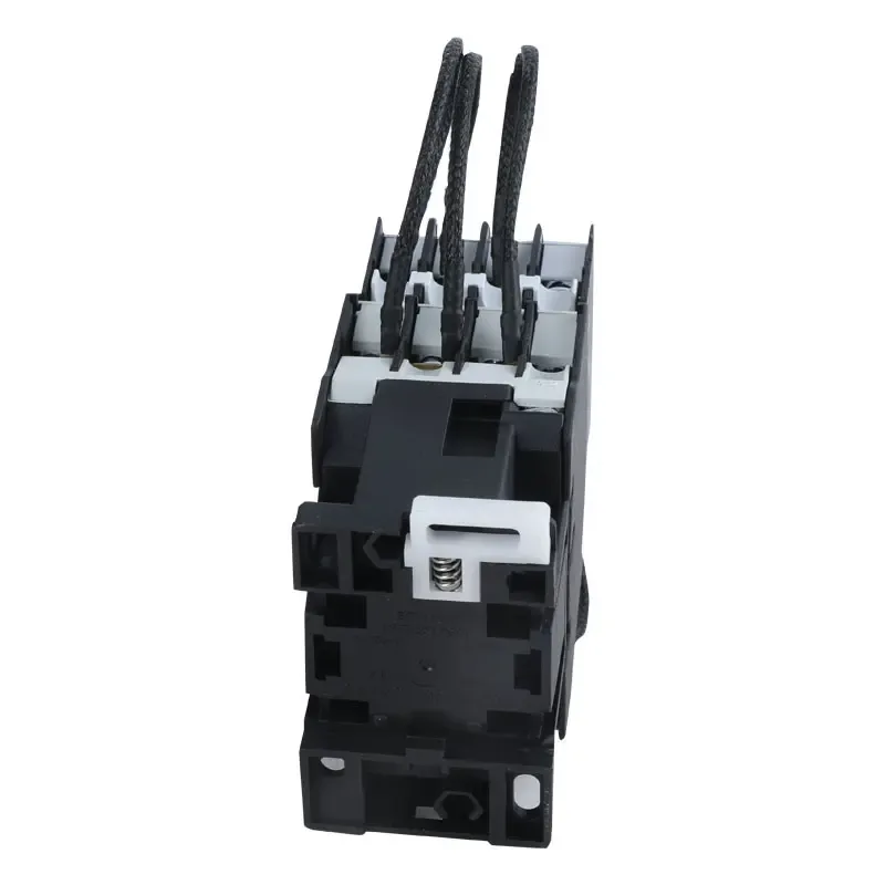
The CJ19 series is described for low-voltage shunt-capacitor switching and reactive-power compensation equipment at 380 V, 50 Hz. The same product description gives a rated operational voltage up to 400 V at 50 or 60 Hz and a restraining device intended to reduce closing inrush and switching overvoltage. It presents a compact direct-acting, double-break structure, covered terminals and screw or 35/75 mm rail mounting options.
Model selection starts with the capacitor current rather than the contactor’s thermal-current label. The published table lists controllable capacitor capacity at 220 V and 380/400 V, conventional thermal current (Ith), operational current and auxiliary-contact data. Values below are transcribed for early sizing; obtain the latest datasheet and coordinate with the capacitor manufacturer before release.
| Model group | Published capacitor capacity at 380/400 V (kvar) | Conventional thermal current Ith (A) | Published operational current at 380/400 V (A) |
|---|---|---|---|
| CJ19-25 | 12 | 25 | 17 |
| CJ19-32 | 18 | 32 | 23 |
| CJ19-43 | 20 | 43 | 29 |
| CJ19-63 | 30 | 63 | 43 |
| CJ19-95 | 50 at 400 V | 95 | 72.2 at 400 V |
| CJ19-115 to CJ19-170 | 60–90 at 400 V | 200–275 | 87–130 at 400 V |
Selection checks that prevent nuisance failures
1. Calculate the stage current
For a three-phase bank, estimate line current with I = Q/(√3 × V), where Q is the stage rating in var and V is line-to-line voltage. Use the capacitor maker’s rated current and tolerances for final selection. Do not substitute the contactor’s Ith for capacitor-duty current; thermal-current categories are tested under different conditions.
2. Match coil and control voltage
The CJ19 page lists control-voltage options of 110, 127, 220 and 380 V. Confirm whether the control circuit is AC or DC, check pickup and drop-out limits, and suppress coil transients where the control system requires it. A mismatched coil can cause chatter that looks like a capacitor problem.
3. Coordinate stages, fuses and discharge time
Use a dedicated capacitor fuse or breaker strategy recommended by the bank designer. Respect the capacitor’s discharge resistor and minimum re-energization time; closing a charged stage can multiply inrush. Verify that the controller’s step delay allows the contactor to open fully before a rapid reclose.
4. Confirm environment and mounting
W9 lists an ambient range of −5 °C to +40 °C, average 24-hour temperature no higher than +35 °C, installation below 2,000 m, pollution degree 3 and installation category III. Keep the panel ventilated, maintain the specified vertical orientation and provide clearance for terminal covers. Humidity control matters because condensation can lower insulation resistance.
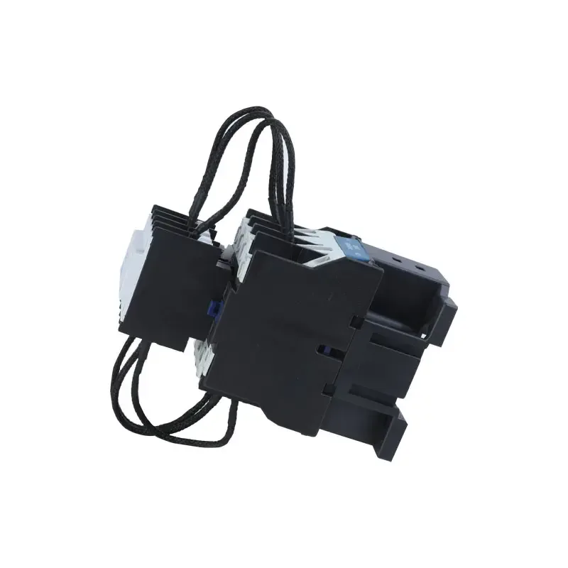
Value comparison: capacitor-duty versus general-purpose switching
The right comparison is not a unit-price contest. It is the risk and total cost of switching the specified bank for its service life.
| Decision dimension | CJ19 capacitor AC contactor | General-purpose AC contactor | 조달의 의미 |
|---|---|---|---|
| Transient handling | Built-in restraining device is documented for capacitor inrush | Often requires external resistors/reactors, if permitted | Check the complete switching topology, not just the contactor label |
| Steady-state duty | Published capacitor capacity and operational-current table | Motor AC-3 data may not represent capacitor duty | Use capacitor kVAr and voltage as primary inputs |
| Installation | Covered terminals; screw or 35/75 mm rail options | Mounting varies by frame | Confirm panel footprint and conductor bend radius |
| 보수 | Direct-acting double-break structure; replaceable contacts are described | Contact wear can be accelerated by inrush | Record switching cycles and inspect after commissioning |
| Total cost of ownership | May reduce extra inrush-control hardware and unplanned outages | Lower initial cost can be offset by failures | Compare installed cost, downtime and spares |
Standards, tests and compliance boundaries
IEC 60947-4-1 is the relevant low-voltage contactor and motor-starter product standard cited by the CJ19 page. It defines service, utilization-category and verification requirements; it is not a blanket certification for every installation. Ask for the manufacturer’s declaration, test basis and applicable utilization category for the intended capacitor bank. IEC 60831-1 addresses low-voltage shunt power capacitors, while IEC 61921 provides guidance for power-factor-correction equipment assemblies. National wiring rules and utility limits can add requirements for harmonic resonance, enclosure temperature and isolation.
Commissioning should include insulation resistance, protective-conductor continuity, phase identification, torque verification and functional cycling. Measure voltage, current, displacement power factor and harmonic distortion with a calibrated power-quality analyzer under representative load. Keep the test report with the single-line diagram and settings. Marketing language such as “certified” or “power-factor guaranteed” should be used only when the exact certificate or contractual test supports it.
How to specify and buy a CJ19 conversion contactor
- Send the supplier a schedule: system voltage/frequency, stage kVAr, number of steps, capacitor type, expected cycles per hour and short-circuit level.
- Request the model-specific table, dimensional drawing, wiring diagram, coil code and terminal torque information.
- Review the coordinated protection study, including fuses, discharge resistors, detuning reactors and controller delay.
- Plan a witnessed factory or site test that records inrush waveform, contactor temperature and post-cycle contact condition.
W9 positions the CJ19 as part of its modular-contactor range. Its product page provides the above ratings and environmental conditions; buyers should still obtain a current drawing and declaration for the destination market. For broader panel coordination, see this guide to modular contactors and the overview of circuit-breaker selection.
자주 묻는 질문
What is a CJ19 conversion capacitor AC contactor?
It is a contactor series intended to switch low-voltage shunt capacitors in reactive-power compensation equipment. Its restraining device is designed to reduce closing inrush and switching overvoltage. Confirm the model, voltage and capacitor duty before substitution.
Can a CJ19 replace a motor contactor?
Only for the capacitor-switching duty for which it is specified. A CJ19 is not a universal motor starter; motor loads require their own utilization category, overload protection and short-circuit coordination.
Which CJ19 size should I choose for a 30 kvar stage?
The published table lists 30 kvar at 380/400 V for CJ19-63. Treat that as a starting point, then verify capacitor tolerance, voltage, ambient temperature, controller cycles and the manufacturer’s latest data.
What control voltages are available?
The product page lists 110, 127, 220 and 380 V control-voltage options. Coil frequency and wiring must match the control transformer or PLC output; specify the exact code on the purchase order.
How do I verify performance after installation?
Inspect torque and insulation, cycle each step, and record inrush, steady current, temperature and power factor with calibrated instruments. Recheck after the plant reaches normal load, because light-load testing can hide resonance or nuisance switching.
참고문헌
- W9 Group CJ19 product page and published ratings
- IEC 60947-4-1, Low-voltage switchgear and controlgear—Contactors and motor-starters
- IEC 60831-1, Shunt power capacitors of the self-healing type
- IEC 61921, Power capacitors—Low-voltage power factor correction banks
Closing principle: capacitor banks reward disciplined switching design; the quietest panel is usually the one specified around measured transients, not the cheapest contactor.
Need a model check, dimensional drawing or coordinated quotation? Review the CJ19 conversion capacitor AC contactor 그리고 contact W9 Group’s technical team with your bank schedule and destination-market requirements.