































DC MCCB (DC Molded Case Circuit Breaker) Basic Guide
DC MCCB (DC Molded Case Circuit Breaker) Basic Guide
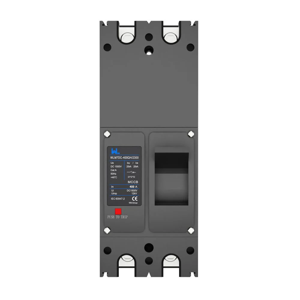
When a solar-storage project engineer in Phoenix reused an AC breaker on a DC feeder, the cable lug began overheating within minutes of commissioning. The visible failure looked like a loose termination, but the reversal was more important: the breaker’s DC arc-extinguishing duty, polarity arrangement and voltage rating did not match the feeder. A familiar AC label had hidden a specification problem.
요약: A DC MCCB must be selected for direct-current arc interruption, pole polarity, continuous current, voltage and prospective short-circuit current—not simply for ampere size. IEC 60947-2 is the core product standard, with IEC 60947-1 general rules and IEC 60364-4-43 installation principles; UL 489 may apply in North American equipment. Record the fault level and cable derating, then approve a model whose tested ratings and wiring diagram match the project.
A DC molded case circuit breaker is a resettable low-voltage protective and switching device designed to open a direct-current circuit during overload or short circuit. Distributors, EPC contractors, OEM panel builders and facility teams use it on photovoltaic strings, battery racks, EV infrastructure and industrial DC buses. Unlike AC, DC current does not naturally cross zero every half-cycle, so the breaker needs an appropriate contact gap, magnetic field control and arc chute. The result is a product choice tied to system topology and evidence, not a generic “breaker” substitution.
For general molded-case background, buyers can also compare the overviews from Religare Electric 그리고 Moreday; their broad AC discussions still need to be narrowed to the declared DC duty of the selected model.
Why DC interruption is different from AC interruption
In AC, the current waveform regularly reaches zero, helping an arc extinguish. In a DC circuit the current can remain continuous, so the contact arc persists and can re-strike unless the device has adequate opening speed, gap and arc-quenching geometry. A DC circuit protection review therefore starts with source voltage, current direction, inductance and available fault energy.
Photovoltaic arrays and batteries can sustain fault current for very different durations. A battery bus may deliver a high initial pulse; a PV array may be current-limited yet maintain an arc under full irradiance. Under IEC 60947-2, verify the declared DC utilization category, number of poles in series, rated operational voltage (Ue), 전류값(In) and ultimate/service short-circuit capacities (Icu/Ics). Never infer a DC breaking rating from the AC column in a catalogue.
Ratings, polarity and wiring checks that prevent overheating
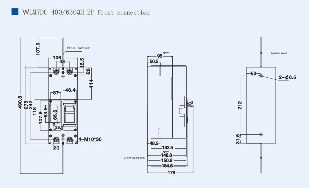
Start with the feeder’s design current and conductor ampacity at the actual ambient temperature. Then check the breaker’s DC voltage per pole and the manufacturer’s permitted pole connection. Some devices require two or more poles in series for a given voltage; reversing a polarised device or bypassing a designated pole can reduce interruption performance. The wiring diagram is part of the safety rating.
Thermal trip settings protect against sustained overload, while magnetic or electronic functions respond to high current. In a battery installation, account for bidirectional current, pre-charge circuits and charger backfeed before deciding whether a single device or separate protection in each direction is required. Tighten terminals to the specified torque and inspect for discoloration; an undersized lug or loose joint can create heat even when the trip unit is correctly set.
DC MCCB versus MCB: where each device fits
MCCB vs MCB is a coordination and duty question, not only a frame-size comparison. A DC MCB is compact and useful on lower-current branch circuits when its DC voltage, polarity and breaking capacity are explicitly declared. An MCCB offers a larger frame, higher current range and often adjustable long-time, short-time and instantaneous protection, which helps coordinate feeders, inverters and battery combiner panels.
For procurement, compare the tested DC Icu/Ics, terminal capacity, temperature derating, mechanical endurance and accessory options. A smaller MCB can be the right answer for a string circuit; an MCCB may be necessary for a 250 A feeder or where selectivity settings are required. The honest answer in an MCCB vs MCB decision comes from the one-line diagram, not a universal current threshold.
| Dimension | DC MCB | DC MCCB | Project implication |
|---|---|---|---|
| Typical role | Branch, string or auxiliary circuits | Feeders, combiner outputs and main DC distribution | Match frame size to conductor and fault study |
| Adjustment | Usually fixed thermal-magnetic curve | Often adjustable or electronic trip options | Supports selectivity and staged shutdown |
| DC breaking duty | Device-specific; check pole series rules | Higher frame ratings; still model-specific | Use declared DC Icu/Ics, never AC-only data |
| Installation effort | Compact DIN-rail assembly | Panel mounting, larger lugs and accessories | Allow heat dissipation and maintenance clearance |
| Total cost | Lower unit cost at modest ratings | Higher unit cost, potentially lower coordination and downtime risk | Evaluate TCO, testing and spares—not purchase price alone |
Applications and selection by DC system dimension
Use the system’s operating envelope to narrow the shortlist. PV strings have high open-circuit voltage and weather-driven current; battery racks add stored energy and possible reverse feed; EV and industrial buses may have repeated switching or regenerative currents. A DC circuit protection schedule should identify the source, normal current, maximum voltage, fault current, isolation point and required trip coordination for each branch.
| 응용 | Critical data | Preferred review action |
|---|---|---|
| PV combiner or array feeder | Voc at minimum temperature, Isc, string count and polarity | Confirm per-pole voltage, series-pole diagram and reverse-current withstand |
| Battery energy storage | Short-circuit current, chemistry, bidirectional flow and pre-charge | Check Icu/Ics, interrupting time, accessories and arc-flash study |
| Inverter DC link | Ripple, inrush, capacitor energy and manufacturer disconnect rules | Coordinate with inverter protection and verify isolation category |
| EV or industrial DC bus | Continuous load, regenerative current, ambient and enclosure | Set thermal margin, cable derating and maintenance access |
Standards, testing and market compliance
IEC 60947-2 covers low-voltage circuit-breakers, including performance and test requirements relevant to industrial DC applications. IEC 60947-1 supplies common definitions and general rules, while IEC 60364-4-43 addresses overcurrent protection in low-voltage installations. Where a product is intended for equipment evaluated in the United States or Canada, UL 489 may be applicable; confirm the exact edition, certification category and end-use conditions with the authority having jurisdiction.
A standard reference is not a blanket certification. Ask for the exact model’s test report, declaration, DC rating tables, polarity diagram, temperature-rise results and production inspection records. W9 Group, a China low-voltage protection manufacturer established in 2020, reports a portfolio spanning MCB, RCCB, RCBO, MCCB, SPD, AFDD and related devices, with testing, aging and OEM/ODM support. Its stated IEC, CE, TUV and UL references should be verified against the model and destination market before a claim appears in a bid or datasheet.
Procurement checklist and W9 Group options
- Build the duty sheet: list Ue, In, fault current, load profile, ambient temperature and conductor size.
- Confirm topology: mark positive/negative polarity, bidirectional paths and the required number of poles in series.
- Check coordination: compare trip curves with fuses, contactors, inverter limits and upstream protection.
- Review evidence: obtain model-level IEC 60947-2 or UL 489 documentation, drawings, torque data and test records.
- Plan lifecycle: specify spare units, inspection intervals, thermal scans and a replacement procedure.
For a sourcing shortlist, review W9 Group’s low-voltage protection products and the WLM7HU photovoltaic solar MCCB against the approved one-line diagram. Use the technical support resources to request ratings and wiring evidence before substituting an AC device.
자주 묻는 질문
What is a DC MCCB breaker?
A DC MCCB is a molded-case circuit breaker engineered to interrupt direct current during overloads and short circuits. Its DC voltage, pole arrangement, polarity and Icu/Ics must be declared for the intended circuit. Confirm the manufacturer’s wiring diagram before installation.
What is a MCCB molded case circuit breaker?
A molded case circuit breaker combines insulated housing, contacts, an operating mechanism and thermal-magnetic or electronic releases in one resettable device. In a DC application, a DC molded case circuit breaker also needs tested arc-quenching performance at the stated voltage and current. The case shape alone does not prove DC suitability.
What is the 80% rule for circuit breakers?
In many North American applications, the 80% rule means a breaker supplying a continuous load is commonly sized so the continuous portion does not exceed 80% of its rating, unless the equipment is specifically listed for 100% operation. Apply the governing electrical code, ambient derating and manufacturer instructions; do not transfer the rule across markets without checking local requirements.
How to wire a DC circuit breaker?
Follow the exact polarity marks, terminal labels and series-pole diagram supplied for the model; some breakers require poles in series to achieve the declared DC voltage. Isolate all sources, verify absence of voltage, torque terminals to specification and test insulation and trip operation. A qualified electrician should approve the final wiring.
How does MCCB vs MCB affect a solar-storage design?
Choose an MCB for a suitably rated branch circuit and an MCCB when feeder current, interrupting duty, adjustment or coordination demands are higher. In either case, a DC circuit protection study must verify voltage, polarity, fault current and derating. Model-level test evidence is more important than the product’s frame label.
참고문헌
- IEC 60947-2: Low-voltage switchgear and controlgear – Circuit-breakers.
- IEC 60947-1: 일반적인 규정.
- IEC 60364-4-43: Protection for safety – Protection against overcurrent.
- UL 솔루션: UL 489 성형 케이스 방식 차단기.
- Religare Electric: Complete guide to molded-case circuit breakers.
Reliable DC circuit protection starts with the arc, polarity and fault study—not with an AC part number that happens to fit the panel. Treat every DC molded case circuit breaker as a tested system component, and let the evidence settle the MCCB vs MCB choice. When your project needs model-level review, ratings or OEM/ODM documentation, contact W9 Group before procurement is locked.