



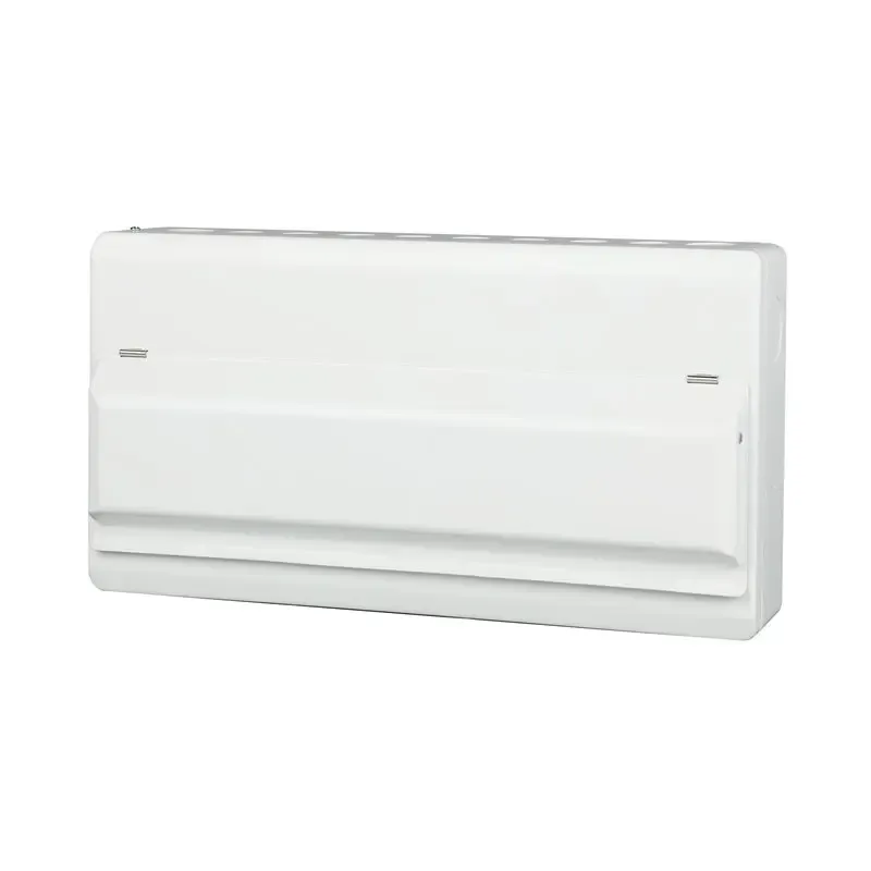





Circuit Breaker Auxiliary Contacts for Enhanced Control and Monitoring
An auxiliary contact can make a breaker’s local state visible to a control system, but it does not replace the breaker’s protective function. A hospital feeder monitoring point must distinguish intentional OFF, normal ON and a protective trip, then preserve a trustworthy state when control power or communications fail.
Summary: An auxiliary contact follows the breaker mechanism’s position, while an alarm contact is intended to report a protective trip or fault state. The exact AX, AL or equivalent accessory must match the frame, terminal arrangement, contact rating and control voltage. Define a signal truth table, test each state and document fail-safe behavior before connecting a PLC or BMS.
Auxiliary Contacts for Breaker Monitoring
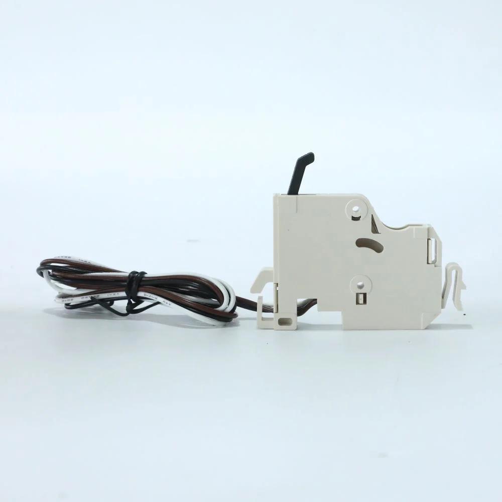
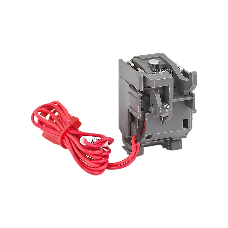
A breaker handle tells a person what happened locally; an auxiliary contact gives a controller an electrical fact. A normally open (NO), normally closed (NC), or changeover contact follows the mechanism and allows a PLC, BMS, generator controller, or annunciator to confirm that a feeder is open or closed. This feedback prevents a remote command sequence from assuming that a breaker moved when its operating mechanism is actually blocked.
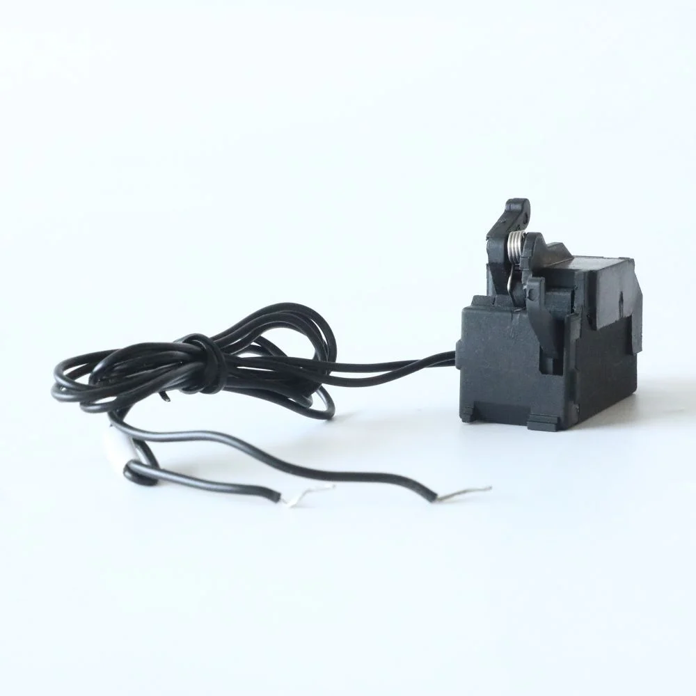
Two signals must remain distinct: an auxiliary contact normally reports the mechanism’s ON or OFF position, while an alarm contact reports the protective event defined by the breaker family. A controller should not infer “tripped” from an ordinary OFF indication. Use separate points and a cause-and-effect table when the distinction affects an automatic transfer or shutdown sequence.
- AX (auxiliary/position): changes state when the breaker is opened or closed, including a deliberate manual opening.
- AL (alarm/trip): changes state after a free trip caused by overload, short circuit, undervoltage release, residual-current protection, or another protective action defined by the breaker.
- Combined assemblies: provide both channels in one accessory, but the terminal truth table still governs the software logic.
Auxiliary Contact Signal Path
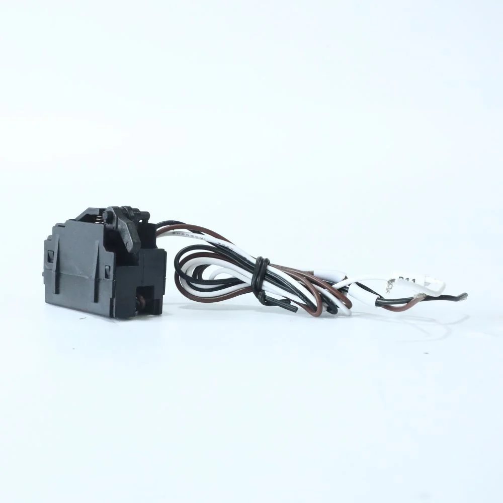
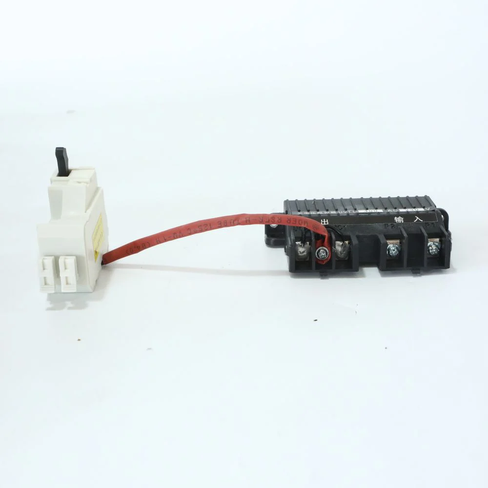
The mechanism moves a small contact block; the block changes continuity in a low-energy circuit. The PLC input then interprets that continuity as “closed,” “open,” or “alarm.” The auxiliary contact does not increase the breaker’s interrupting rating and should never be treated as a spare power pole. It is an observation and interlock path.
Verify Three Operating States
For each project, document at least three operating states: breaker ON, normal OFF and protective trip. Add control-power healthy, communication healthy and reset states where the system depends on them. Test the contact with the specified meter or controller input, record the terminal mapping and retain the result with the panel’s as-left documentation.
The distinction has operational value. In an automatic transfer scheme, “normal OFF” can be an intentional maintenance command, whereas “AL active” may require a lockout, inspection, and event record. Treating both as a single OFF status hides the root cause and can produce an unsafe restart.
Build the Three-State Truth Table
List the expected contact state for normal ON, intentional OFF and protective trip, then add what the PLC or BMS should display for each state. Mark normally-open and normally-closed terminals, control voltage, fuse protection and the state on loss of auxiliary power. Test the table at the panel before relying on remote indication.
Auxiliary Contact Compatibility
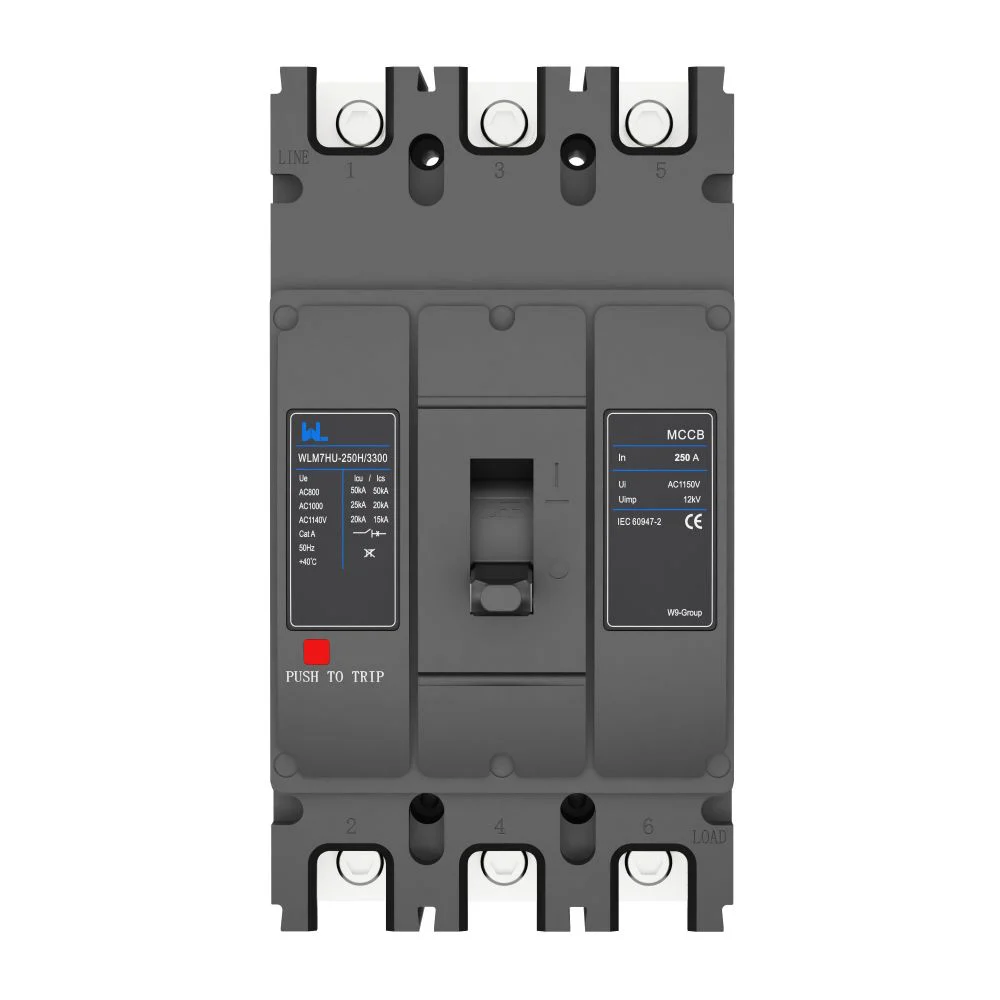
Start with the breaker frame, not the control voltage. Common frame-coded families pair AX-125 with 125/160-frame breakers, AX-250 with 250-frame breakers, and AX-400 with 400-frame breakers; corresponding AL codes follow the same pattern. A similar-looking accessory from another frame may not latch or may hold the mechanism away from its normal position.
Then match the electrical duty. Representative AX/AL data list Ue of AC 230/400 V and DC 24/110/220 V, with In of 0.3 A on AC and 0.15 A on DC. Those limits suit many PLC or interposing-relay circuits, but an inductive coil, lamp inrush, or long cable can impose a different duty. Confirm utilization category, suppression, fusing, conductor area, and terminal torque in the selected data sheet; do not infer these values from a product photograph.
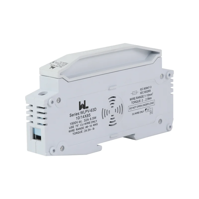
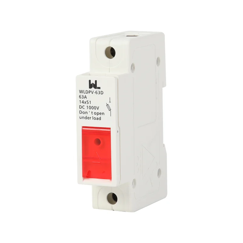
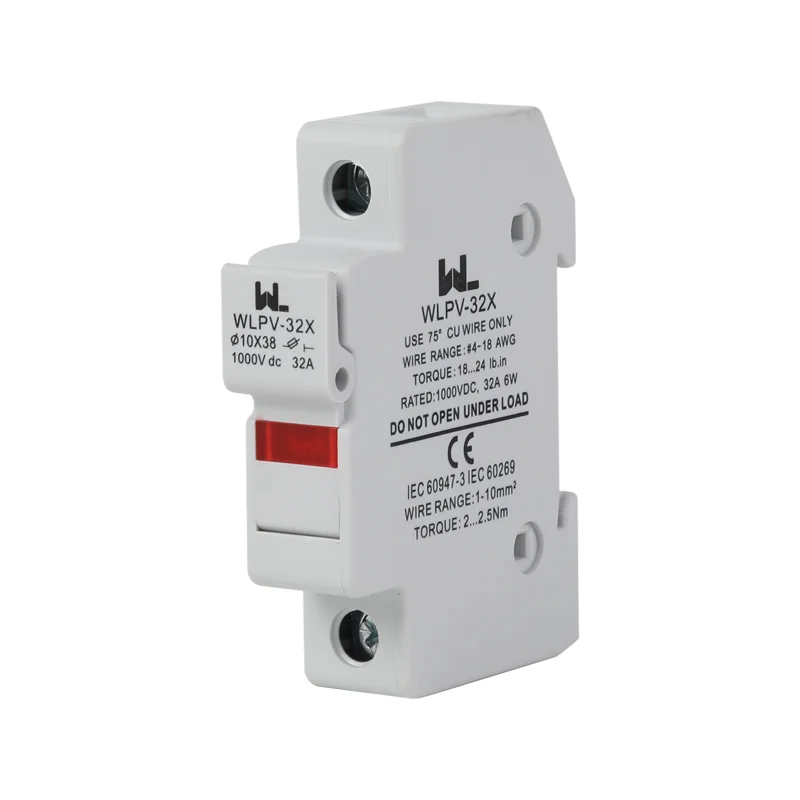
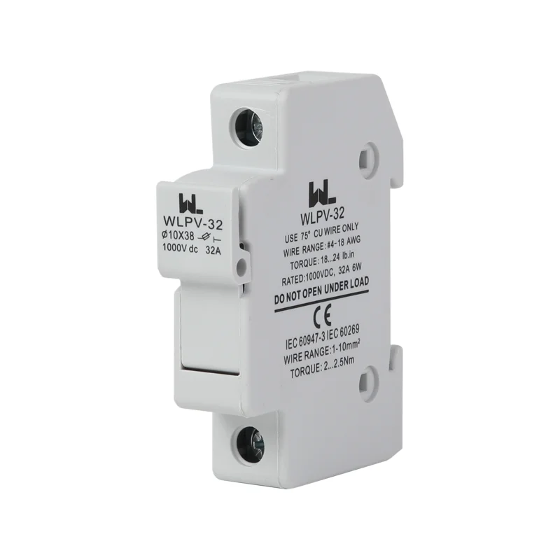
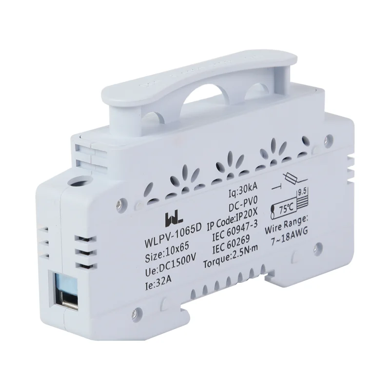
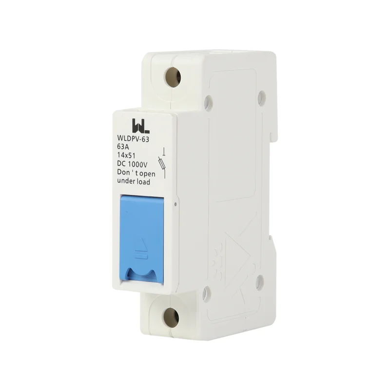
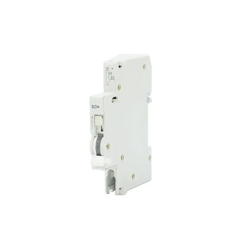
Compact DIN-rail accessories show why environmental details belong in the purchase specification. One published configuration lists 0.5–2.5 mm² conductors, Ui up to 500 V, Uimp 4 kV, IP20, a 1-pole/9 mm width, 1 N·m terminal torque, 6,050 electrical operations, and 10,000 mechanical operations. Another narrow format lists 0.8 N·m torque and an ambient range of −5 to +40 °C. These are catalogue test conditions—not a promise of identical life in a hot, high-cycle enclosure.
Match the Accessory to the Breaker Frame
Verify the accessory code, mounting position, terminal block, contact category, current or voltage limit and operating mechanism for the exact breaker frame. A similar-looking contact block may not share the same terminal numbering or mechanical travel. Keep the wiring diagram and accessory identification with the purchase order and commissioning record.
Control-System Lifecycle Planning
The cheapest accessory is not always the lowest-cost choice. A single combined contact can save panel space, yet separate AX and AL channels usually shorten fault finding because the operator can distinguish a command from a protective event. An interposing relay adds a component but protects a small contact from an inductive load and simplifies future PLC replacement.
| Design choice | Strength | Trade-off | Best control use |
|---|---|---|---|
| AX position contact | Clear ON/OFF feedback | Cannot identify why the breaker opened | Interlock permissive, BMS mimic, remote status |
| AL alarm contact | Separates a free trip from a command | Needs a dedicated input and reset logic | Trip annunciation, event log, maintenance call |
| AX + AL assembly | Compact, two meanings in one accessory family | More terminals and a stricter wiring diagram | Critical feeders and automatic transfer |
| Interposing relay | Handles higher or inductive control duty | Relay cost, coil power, and another failure point | Motor starters, long runs, mixed-voltage panels |
For an illustrative TCO calculation, a relay that costs a few currency units can avoid replacing a contact block after repeated coil inrush; the actual break-even depends on switching frequency, labor rate, and downtime. Record those assumptions rather than presenting a generic ROI percentage.
Breaker Monitoring Applications
| 申請 | 主なリスク | Recommended channel plan | Acceptance evidence |
|---|---|---|---|
| Hospital or commercial feeder | Staff act on a false “healthy” indication | AX to BMS; AL to a prioritized alarm | Manual OFF and simulated trip logged separately |
| Industrial motor circuit | Inductive switching wears contacts | AX/AL into an interposing relay; suppress the coil | Utilization category and relay test record |
| Data-center A/B distribution | Automatic restart after an unexplained trip | Independent AX and AL, latched event history | FAT/SAT interlock and alarm-reset scripts |
| Compact DIN-rail panel | Heat, torque, and wiring space | Choose rated ambient, width, Ui/Uimp, and conductor range | Torque log and enclosure temperature review |
Standards and Compliance Boundaries
IEC 60947-5-1:2024 specifies requirements and tests for control-circuit devices and switching elements, including auxiliary-contact behavior. IEC 60947-5-4 provides methods for assessing the performance of low-voltage control contacts. Both are technical standards; neither is a blanket certificate for every accessory, enclosure, or installed circuit.
North American projects may also invoke UL 1077 for supplementary protectors or another product-specific UL standard. The applicable rule depends on the device, panel, and destination market. Ask for a model- and configuration-level declaration, test report, or certificate scope. Unsupported “certified” wording can cause submittal rejection, re-testing, shipment delay, or a warranty dispute even when the contact itself operates correctly.
Procurement and Commissioning Checks
- Freeze the interface: list frame code, AX/AL function, NO/NC arrangement, Ue, In, conductor size, and terminal torque on the approved submittal.
- Separate meanings in software: map AX to position and AL to trip; define alarm latching, reset, and maintenance bypass states.
- Protect the contact: add an interposing relay and suppression when coil current, inrush, or utilization category exceeds the accessory rating.
- Check environment and endurance: compare ambient and IP limits with the enclosure, then estimate annual operations against the applicable test values.
- Witness FAT/SAT: test ON, normal OFF, protective trip, loss of control power, alarm reset, and restart permissive; retain the signed truth table.
W9 Group provides frame-specific circuit breaker auxiliary contacts and a separate MCCB alarm contact family. For narrow panels, engineers can review the JCOF auxiliary contact format and request a configuration drawing before approval.
Related resource: MCCB alarm contact
Related resource: JCOF補助コンタクト
Frequently Asked Questions
What does a circuit breaker auxiliary contact monitor?
It monitors the breaker’s mechanical position through a low-power NO, NC, or changeover circuit. It can tell a controller that the breaker is ON or OFF, but it does not by itself explain why the breaker opened.
What is the difference between an auxiliary contact and an alarm contact?
An AX auxiliary contact follows normal position changes; an AL alarm contact identifies a free trip or protective operation. Use separate PLC points when operators need to distinguish a planned shutdown from a fault.
補助コンタクトで230Vの負荷を切り替えることはできますか?
Only if the selected contact’s Ue, In, utilization category, and load type allow it. Representative AX/AL data list 0.3 A at AC 230/400 V; use an interposing relay for larger or inductive loads.
How do engineers choose the correct frame accessory?
Match the accessory code to the breaker frame and confirm the manufacturer’s compatibility drawing. For example, AX-125, AX-250, and AX-400 families correspond to different frame groups; a similar housing is not proof of fit.
What should be tested before a monitored breaker is energized?
Verify continuity and software indication for ON, normal OFF, and protective trip; then test alarm reset, interlocks, and loss of control power. Record the final terminal truth table and torque values in the as-built package.
Technical References
- Schneider Electric — Micrologic Trip Units. Official product-range page observed 17 October 2026; illustrates optional signalling and communications for its range only.
- OSHA 29 CFR 1910.303 — General. U.S. requirements for suitable equipment, guarding, ratings and installation evidence. Accessed 17 October 2026.
- Schneider Electric — Icu and Ics on a PowerPact breaker. Official FAQ, modified 10 May 2022; used only for surrounding breaker-duty terminology, not accessory equivalence.
The reliable panel is not the one with the most signals; it is the one whose signals mean exactly what the operator thinks they mean. Specify position, trip, frame, rating, and evidence together—then prove the truth table before the first automatic command. Review W9 Group’s protection-products range or contact the technical team when your monitoring scheme reaches submittal.
Related resource: contact the technical team