




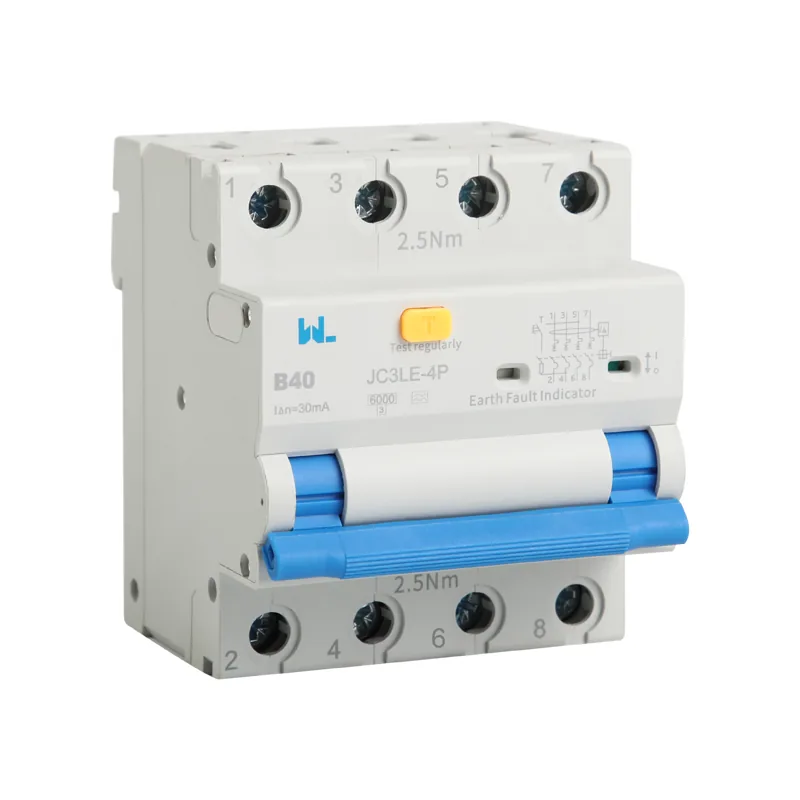
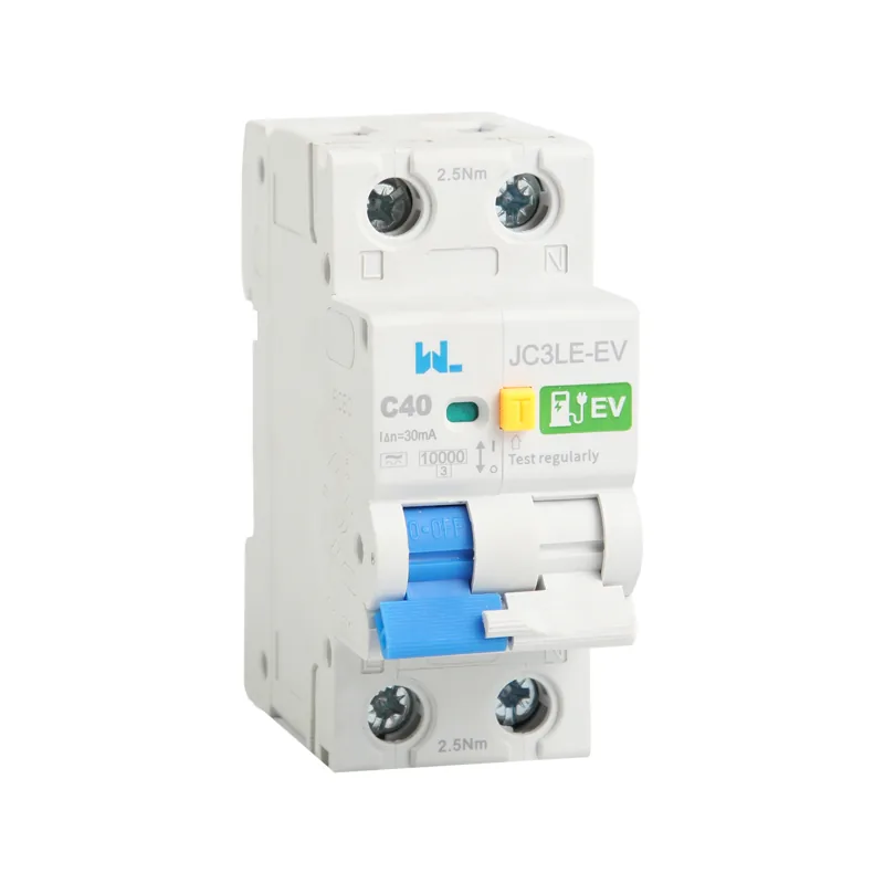
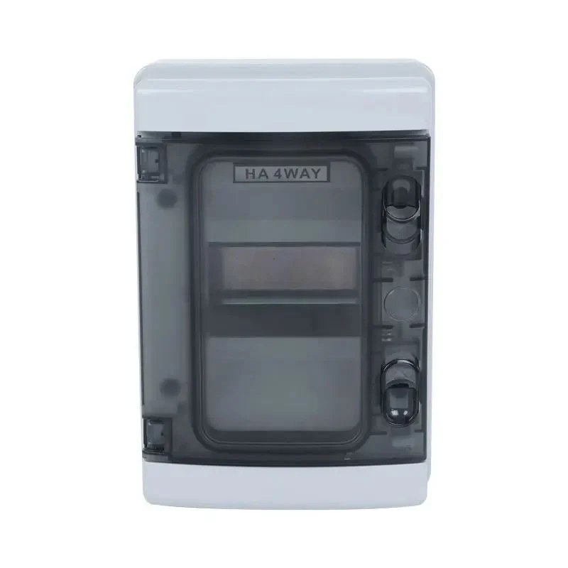
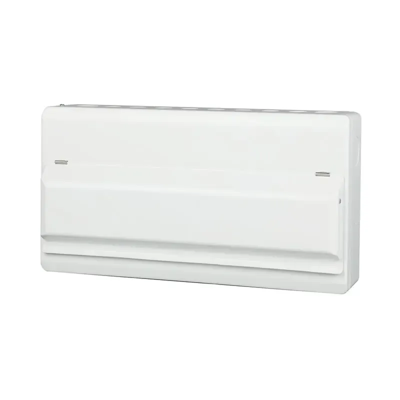





4-Pole RCBO with Alarm 6kA Safety Switch Circuit Breaker JCB2LE-8
A four-pole RCBO can provide circuit-level overcurrent and residual-current protection while reporting a trip remotely, but the alarm wiring is a separate control circuit. A wet-weather trip on a pump feeder should trigger a review of leakage, neutral routing, fault duty and the contact truth table before anyone replaces the breaker or bypasses the alarm.
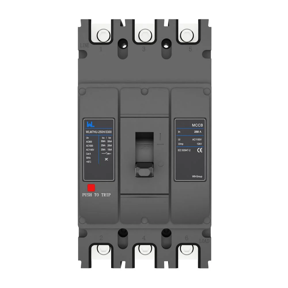
Summary: The JCB2LE-8 article describes a four-pole RCBO with an alarm indication and a stated 6 kA breaking-capacity value. Treat 6 kA as a product rating to compare with calculated prospective fault current, not as universal installation approval. Four poles normally switch the three phases and neutral, while the alarm contact reports a protective event to a PLC or BMS. Confirm the exact variant, residual-current type, sensitivity, contact category and wiring diagram before release.
A four-pole RCBO is useful where a three-phase load has a shared neutral or where local rules require simultaneous isolation. Unlike a simple safety switch, it can open on overload, short circuit or earth leakage. The alarm output is a signalling function, not a substitute for the protective trip; it should be wired to a monitored input and clearly distinguished from the power contacts.
Four-Pole RCBO Protection Functions

The current transformer in an RCBO monitors all live conductors that pass through it. In a four-pole arrangement that normally means L1, L2, L3 and N; any imbalance between outgoing and returning current produces a residual signal. IEC 61009-1 requires the protective functions to operate within declared limits, while IEC 60364-4-41 and IEC 60364-5-53 provide installation principles for protection against electric shock and isolation.
Switching the neutral with the phases helps prevent a floating or back-fed neutral during maintenance. It does not mean the neutral is a protective earth, and it does not permit a shared neutral downstream of separate RCBOs. The installer should identify the supply earthing system, verify conductor identification and torque each terminal to the manufacturer’s value. A continuity and polarity check should precede insulation and RCD tests.
Separate Alarm and Auxiliary Signals
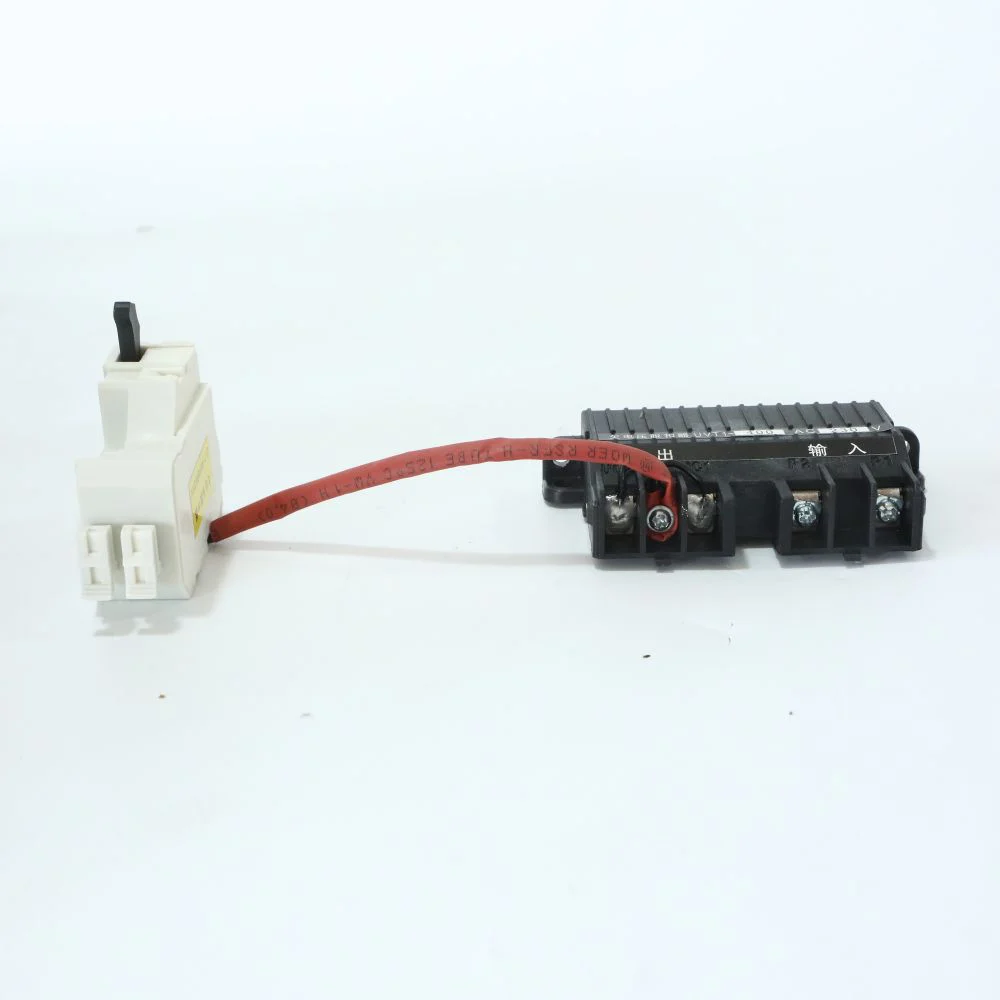
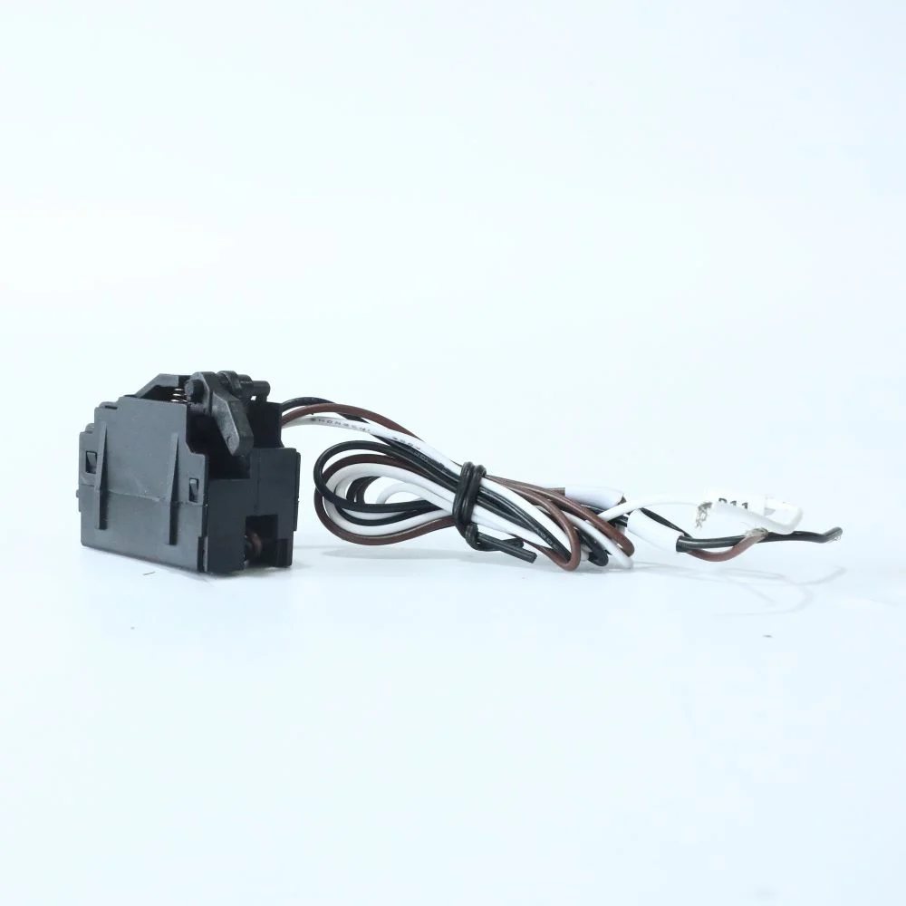
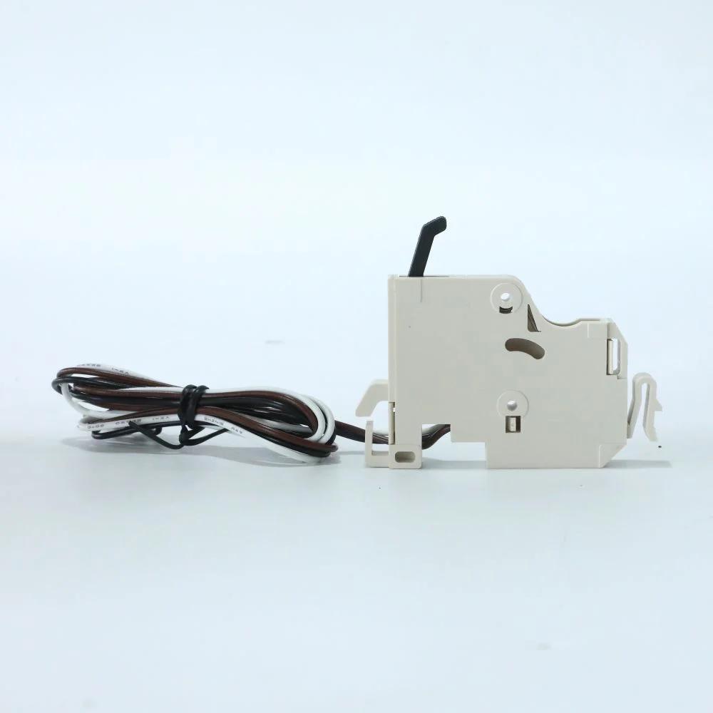
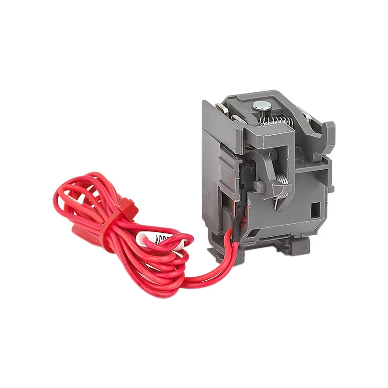
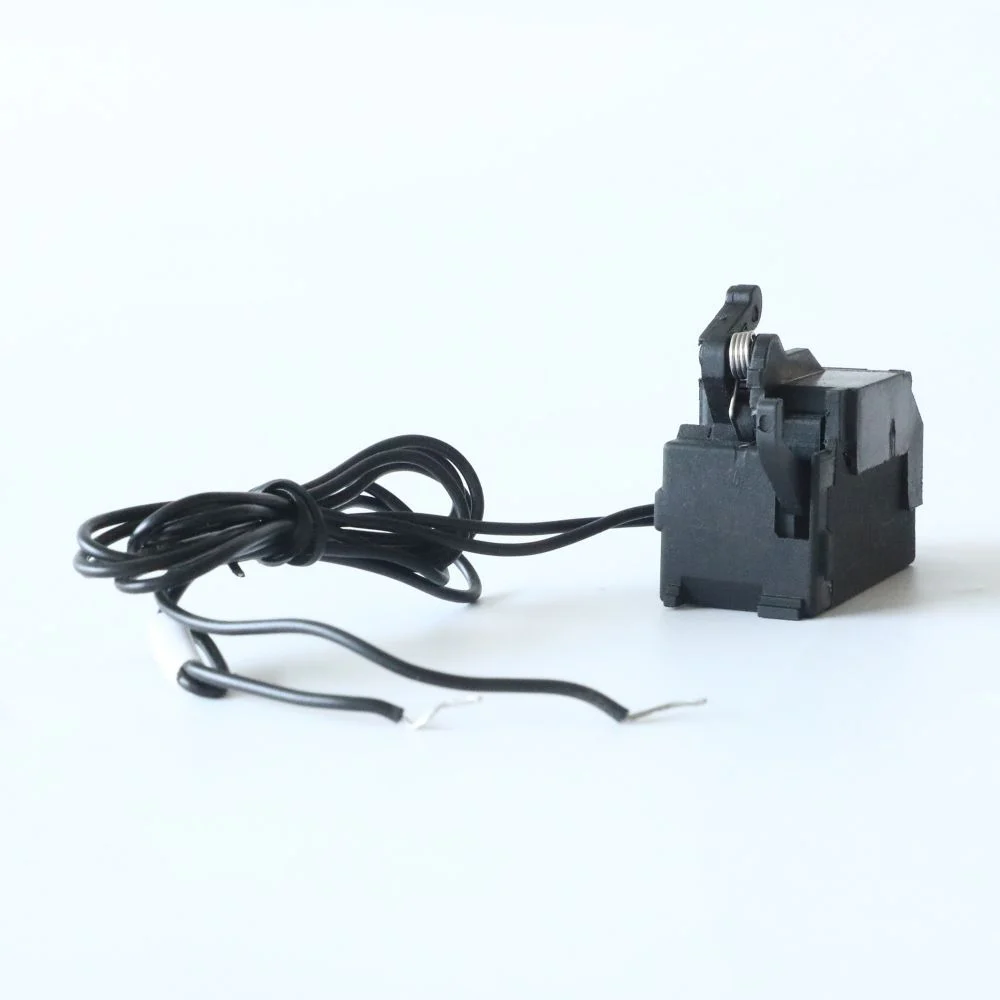
An alarm or trip contact changes state for the protective event defined by the device; a manual OFF position may not create the same signal. An auxiliary contact normally follows the mechanism’s position. Use separate PLC points when the control system must distinguish an intentional shutdown from a fault, and protect the low-energy contact circuit with the specified fuse and wiring.
Map Power and Alarm Contacts
Draw the four power conductors and the low-voltage signalling loop on separate lines. Mark the RCBO’s line and neutral terminals, the alarm common/NO/NC terminals and the receiving PLC or BMS input. Test three states—normal ON, intentional OFF and protective trip—and record which points change. This acceptance table prevents a position signal from being mistaken for a trip signal.
6 kA Rating and Circuit Duty

“6 kA” is the declared short-circuit breaking capacity under the applicable test sequence. It is neither the continuous current nor the residual sensitivity. Calculate prospective fault current at the installation point, then compare it with the exact model, voltage, curve and any accepted backup combination. Do not infer the supplied JCB2LE-8 current range or contact rating from the family name alone.
Overcurrent selection is equally important. The breaker’s rated current (In), cable current-carrying capacity (Iz), installation method and ambient temperature must be coordinated in accordance with IEC 60364-4-43. A 32A circuit, for example, cannot be justified merely because a 32A device is available; the conductor size, voltage drop and duty cycle must support that rating. The JCB2LE-8 name does not, by itself, state In or a B, C or D curve.
| Specification question | なぜ重要なのか | 請求する証拠 |
|---|---|---|
| Breaking capacity | Must exceed calculated PFC at the point of installation. | IEC 61009-1 test declaration and 6kA marking. |
| Rated current and curve | Coordinates cable heating, inrush and selectivity. | Datasheet table showing In and B/C/D characteristic. |
| Residual-current type and sensitivity | Determines response to AC, pulsating DC and leakage. | Type (AC/A/F/B) and IΔn; test-button instructions. |
| Alarm output | Enables remote fault annunciation without carrying load current. | Contact diagram, utilization category and terminal limits. |
Confirm the Ordered RCBO Variant
Before procurement, freeze the ordered current, curve, residual-current type, IΔn, pole arrangement and contact accessory. Then compare the marked breaking capacity with the maximum fault current at the installation point and document conductor ampacity, ambient correction and selectivity. The Schneider 4-pole RCBO product page demonstrates why a model page must list current, curve, breaking capacity, residual type and sensitivity separately; those values cannot be inferred from the words RCBO or safety switch.
RCBO Applications in Monitored Feeders

In a commercial plant room, a remote alarm can reduce the time between a leakage event and a safe response. The value is operational rather than magical: maintenance staff receive a discrete signal, identify the affected feeder and follow a lockout/tagout procedure. For a small installation, the added wiring and commissioning time may outweigh the benefit; for an unmanned pump station, cold room or data-room auxiliary board, early notification can prevent lost production.
Use the alarm as one input in a cause-and-effect plan. Define whether a trip should stop a process, start a standby pump or create a priority message. Never bypass the RCBO because a nuisance alarm is inconvenient. Investigate moisture, insulation damage, inverter leakage and neutral-earth connections with a competent electrician.
| Option | Protection scope | Alarm visibility | Typical procurement implication |
|---|---|---|---|
| Four-pole RCBO with alarm | Overcurrent plus residual current on a three-phase-plus-neutral feeder. | Remote indication of protective trip when correctly wired. | Higher panel integration effort; useful for monitored or unattended loads. |
| Four-pole RCCB plus MCB | Residual and overcurrent functions split between devices. | Requires compatible signalling accessories on the relevant device. | Can simplify replacement strategy, but occupies more space and needs coordination. |
| Three-pole breaker, unswitched neutral | Overcurrent on phases; neutral isolation depends on upstream design. | Usually no residual-trip alarm at the feeder. | May be unsuitable where simultaneous neutral isolation or leakage monitoring is required. |
Product and Installation Evidence
IEC 61009-1 is the principal product standard for residual current circuit-breakers with integral overcurrent protection for household and similar uses. IEC 60364-4-41 addresses protection against electric shock; IEC 60364-4-43 covers overcurrent protection; IEC 60364-5-53 covers selection and erection of switching and control devices. National adoptions—such as BS 7671 in the United Kingdom—may add rules for specific premises.
These standards are not interchangeable certificates. A supplier’s declaration or test report should identify the exact family, pole configuration and ratings; a generic CE statement does not prove that a 6kA claim suits every installation. Commissioning should include visual inspection, protective-conductor continuity, insulation resistance where appropriate, polarity, functional operation of the test button and measured residual-trip performance using an instrument suitable for the device type. Record results with the circuit reference and date.
JCB2LE-8 Procurement Checks
- Calculate PFC and confirm that 6kA is adequate at the mounting point; check upstream coordination.
- Match In and the trip curve to cable ampacity, load inrush, ambient temperature and voltage drop.
- Choose the residual-current type and IΔn required by the equipment maker and local installation rules.
- Map the alarm contact into the control schematic, including fail-safe state, fuse protection and BMS text.
- Require a datasheet, wiring diagram, batch traceability and commissioning record before handover.
For buyers comparing options, use the circuit protection products range and RCBO function guide for terminology, then request the exact JCB2LE-8 documentation. The MCB safety guide separates overcurrent duties from residual-current duties. The product page, contact diagram and installation rules must agree before the device is added to a monitored feeder schedule.
Related resource: RCBO function guide
Related resource: MCB safety guide
Frequently Asked Questions
What does a 4-pole RCBO protect?
It combines overcurrent and residual-current protection while switching three phases and the neutral. The exact residual type, sensitivity and current range depend on the ordered variant, so the datasheet must be checked.
Is 6kA enough for every four-pole circuit?
No. Six kiloamps is a breaking-capacity rating. Compare it with the calculated prospective fault current at the installation point and use backup protection or a higher rating when required.
What does the alarm contact indicate?
It normally reports a protective trip to a remote indicator, PLC or BMS. It is not a load contact; follow the supplied contact diagram and verify whether manual switching changes the signal.
Which standard applies to an RCBO with integral overcurrent protection?
IEC 61009-1 is the key product standard. Installation requirements come from the applicable national wiring rules and the relevant IEC 60364 sections; a product standard does not replace site design verification.
How should the JCB2LE-8 be commissioned?
After de-energised wiring checks, an authorised electrician should verify polarity, insulation and protective-conductor continuity, operate the test button and measure residual-trip behaviour with a compatible tester. Record the results and investigate any unexpected alarm or trip before energising the load.
Technical References
- Schneider Electric — Acti9 iC60 4P RCBO A9D97416. Official product page observed 17 October 2026; illustrates separate current, curve, 6 kA, residual type and 30 mA fields, not JCB2LE-8 equivalence.
- OSHA 29 CFR 1910.303 — General. U.S. requirements for suitable equipment, instructions, interrupting rating and coordination. Accessed 17 October 2026.
- IEC 61009-1 — RCBO product standard reference. Product-standard reference; installation rules and exact edition remain project-specific. Accessed 17 October 2026.
The dependable installation is not the one with the longest feature list; it is the one whose fault level, isolation strategy and alarm response are proven on paper and at the terminals.
When that decision point arrives, review the JCB2LE-8 4-pole RCBO category with your project’s PFC, load schedule and wiring rules, then contact the supplier for the current datasheet, wiring diagram and application support.