




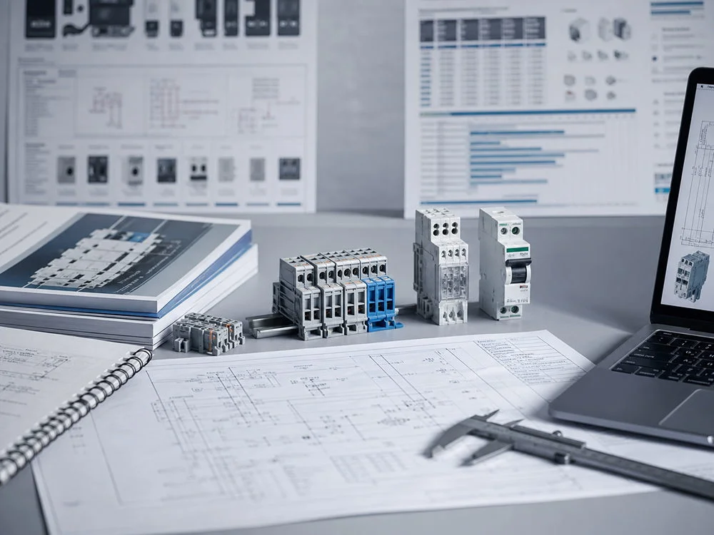


DC MCCB for Solar and Battery Storage: Sizing, Poles, and Interrupting Capacity
A battery-storage extension can turn an existing solar DC cabinet into a different protection problem. The nominal bus voltage may remain unchanged, but the available fault current, current direction and operating profile can change substantially. Reusing the original breaker because its ampere marking looks sufficient skips the most important part of the review: the source duty.
Quick answer: DC MCCB sizing requires separate checks for voltage, continuous current, cable protection, fault interruption and the approved pole arrangement. PV and battery systems can impose different fault conditions even at the same bus voltage. Start with source-specific data and the network study, then select a trip unit and installation configuration within the manufacturer’s declared envelope. Verify Icu and Ics where applicable at the intended DC voltage, including any stated circuit conditions. Do not infer battery suitability from a solar label or assume bidirectional operation from a DC marking. Current sizing is necessary, but it cannot establish interruption capability by itself.
Start with the source and fault study
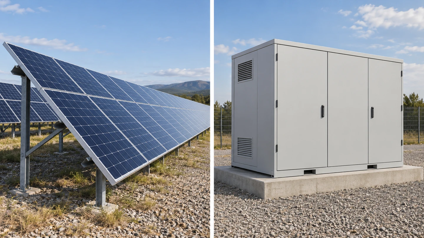
A PV source is governed by its module and array characteristics. Parallel strings can contribute reverse current into a faulted path, while inverter and other connected equipment can affect the study. Battery fault behaviour depends on chemistry, state, internal impedance, configuration and the manufacturer’s data, together with the external circuit. Do not replace that information with a general current multiplier.
Identify all sources that can energize the protected section. A hybrid system can include PV, batteries, converters and capacitors, with several possible operating states. State which devices are connected during normal operation, charging, discharge and maintenance. The prospective fault current must represent the relevant state and location rather than an unrelated value at another bus.
For a simplified inductive DC circuit, L/R describes a time constant relevant to current behaviour. Compare the actual study assumptions with the manufacturer’s declared interruption conditions. A short-circuit current value without its application conditions may be inadequate for approval. Do not assign a universal time constant to all PV arrays or all battery racks.
The MCCB specification guide explains why voltage, current and breaking capacity require separate evidence. For storage projects, the same discipline applies to a DC figure tested under conditions that do not cover the intended source.
| Input | PV assessment | Battery-storage assessment |
|---|---|---|
| Maximum voltage | Cold array open-circuit voltage and design method | Maximum battery or DC-bus voltage in relevant states |
| Operating current | Array current and required design factors | Charge/discharge duty and minimum operating voltage |
| Fault source | Parallel strings and relevant equipment contributions | Battery data plus network and converter contributions |
| Direction | Normal and possible reverse-current paths | Charge, discharge and fault-current directions |
| Interruption evidence | Declared PV duty and configuration | Declared battery/DC duty and matching conditions |
Size current without losing the protection boundary
Determine the design current from the actual duty. For a power-controlled converter, a simple P/V calculation may help establish one operating point, but efficiency, minimum voltage, overload capability and continuous-duty requirements can alter the result. A battery operating over a voltage range can draw more current at the low-voltage end for the same power transfer.
Illustrative arithmetic only: 100 kW divided by 800 V is 125 A before losses and other design allowances. This is not a recommended breaker size. It omits the voltage range, converter limits, cable conditions and project factors. Use such arithmetic to check inputs, then apply the equipment instructions and adopted installation method.
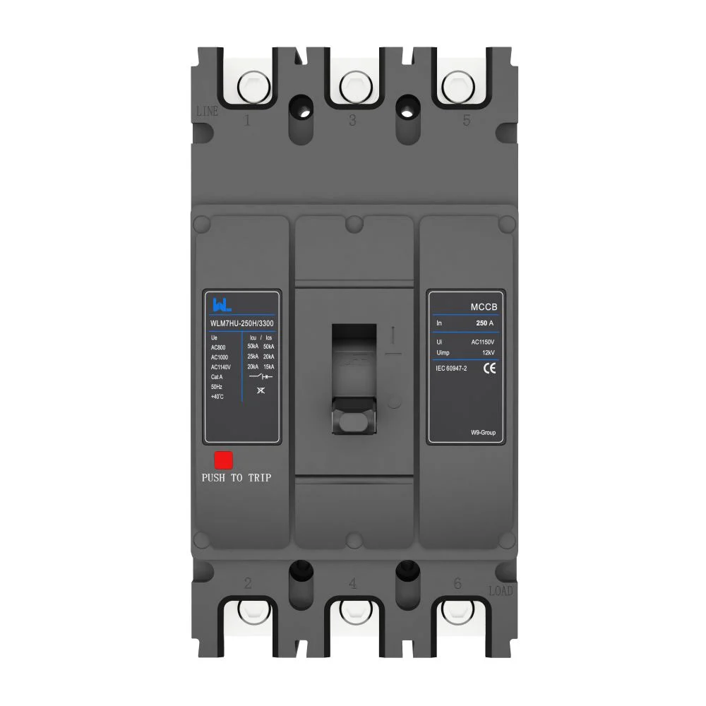
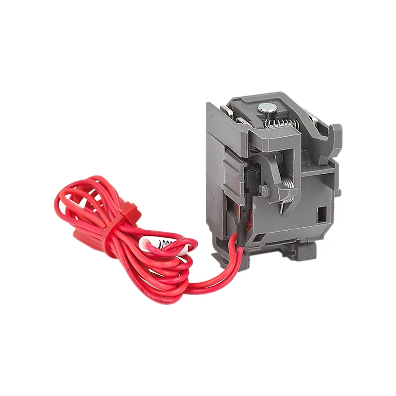
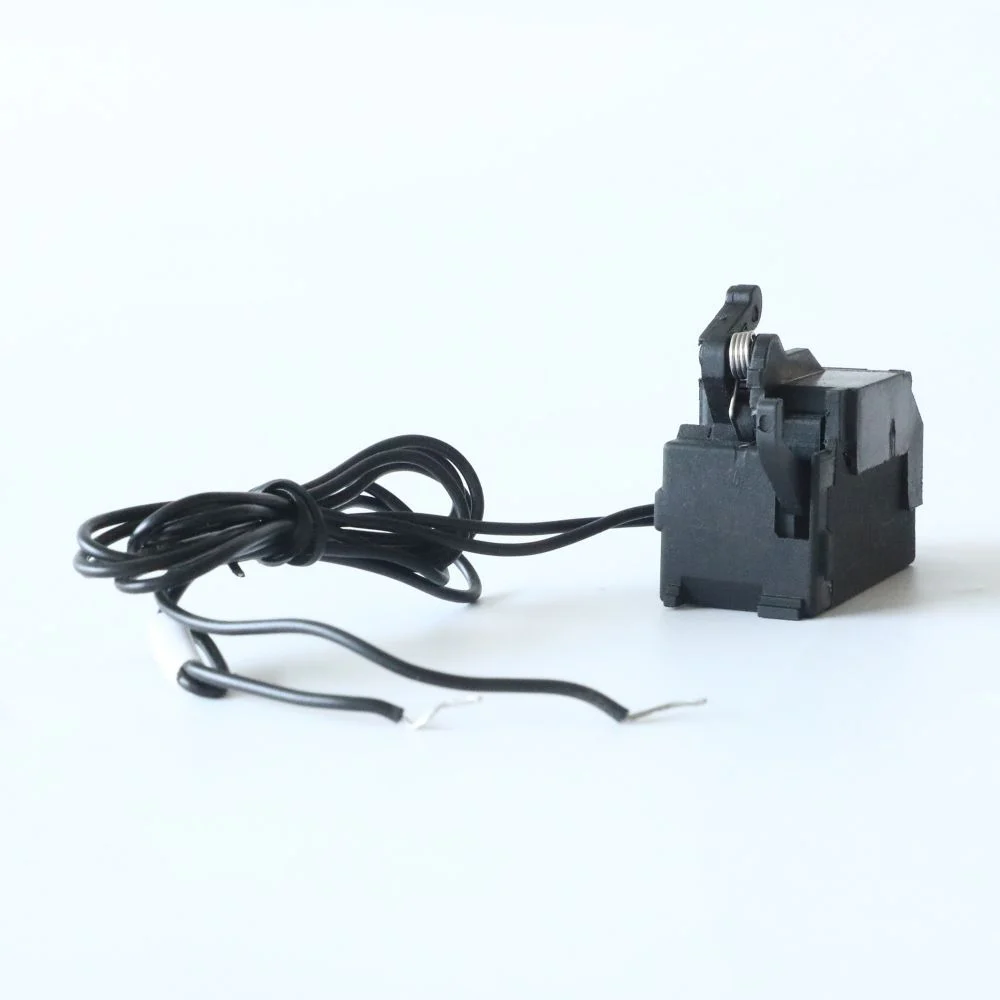
Separate the MCCB frame designation, fitted current rating and adjustable trip settings. A frame can support several versions, but the supplied trip unit determines the available functions and adjustment range. Settings must coordinate with the conductors and connected equipment. Turning a setting upward to avoid an operational trip can remove the intended overload boundary.
Thermal derating connects the catalog rating to the real enclosure. Internal temperature, adjacent loaded devices, ventilation, altitude where relevant, terminal arrangement and conductor installation can affect the permitted duty. Obtain the manufacturer’s installation guidance and the assembly designer’s thermal assessment instead of assuming the open-air catalog condition applies inside a compact cabinet.
Verify interruption and trip performance
DC interrupting capacity must cover the prospective fault duty at the actual operational voltage and approved pole configuration. For IEC-rated MCCBs, Icu and Ics have distinct test meanings. Review the applicable values and the expected service condition after interruption. A larger frame or higher current rating does not automatically supply a higher breaking capacity.
The trip characteristic must also detect and clear the faults the design expects it to address. High interrupting capacity says what the device can break under specified conditions; it does not prove that every possible low-level fault will cause operation within the required time. Coordinate overload, instantaneous or other available functions with the cable and equipment limits.
Battery-management or converter controls may limit current or command shutdown, but their role in the protection design needs documented analysis. A control function is not automatically a substitute for the required fault-interrupting device. Establish what happens if communications, auxiliary power or the control function is unavailable in a relevant fault condition.
Review selectivity and any backup protection using manufacturer data for the exact devices. An upstream and downstream MCCB do not become selective simply because their ampere ratings differ. The study should state which device is intended to operate and what loss of service is acceptable. Retain the coordination evidence with the settings schedule.
Confirm poles and the ordered configuration
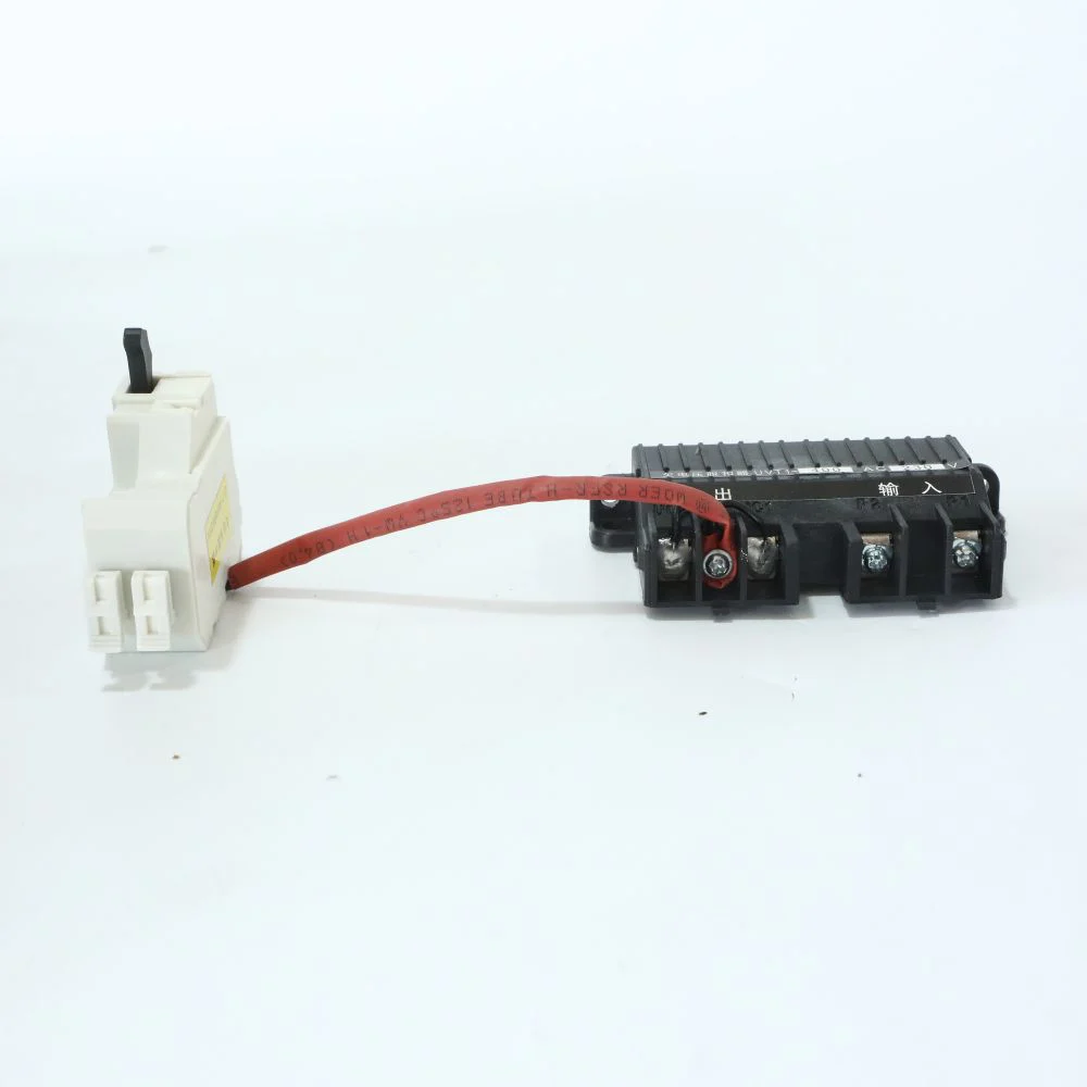
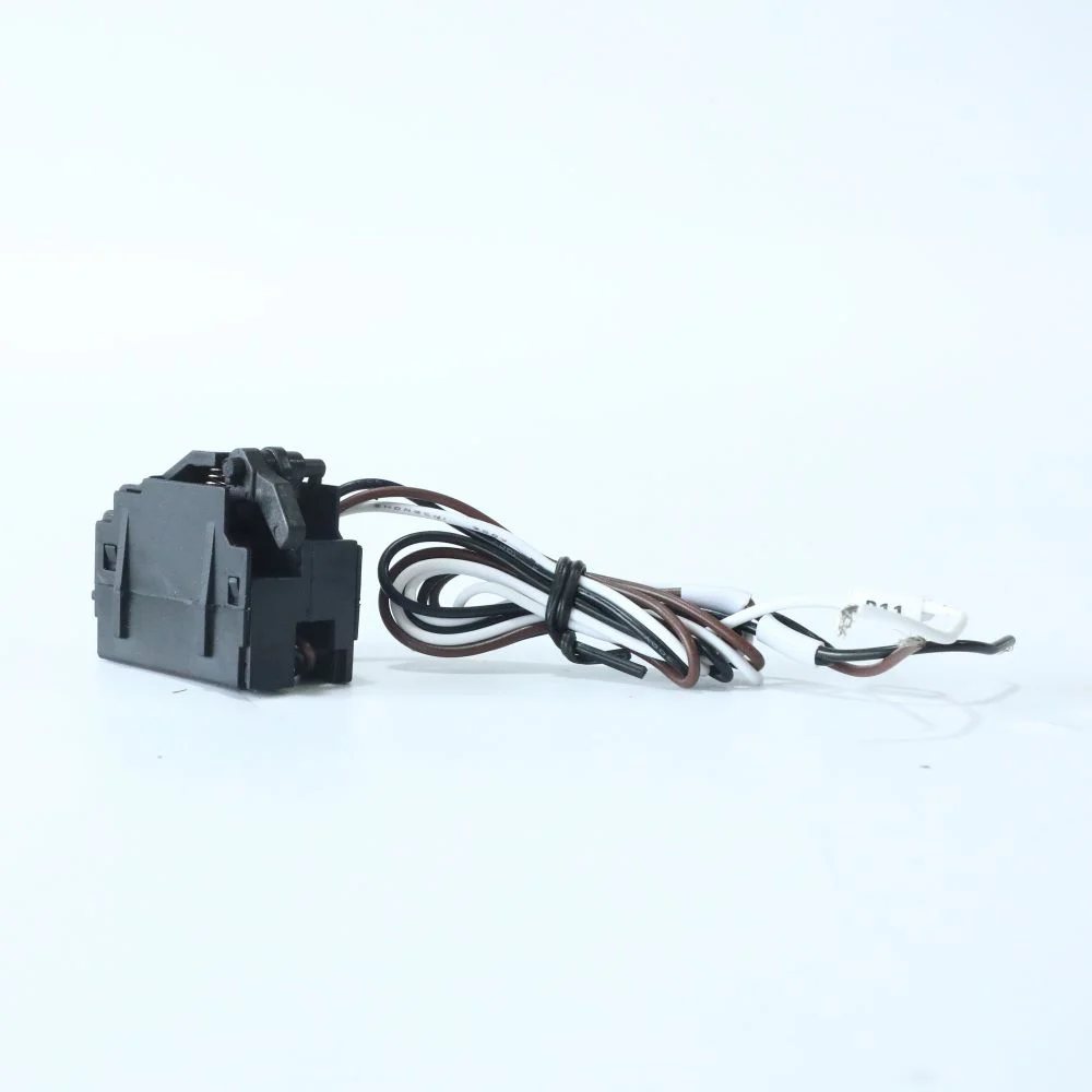
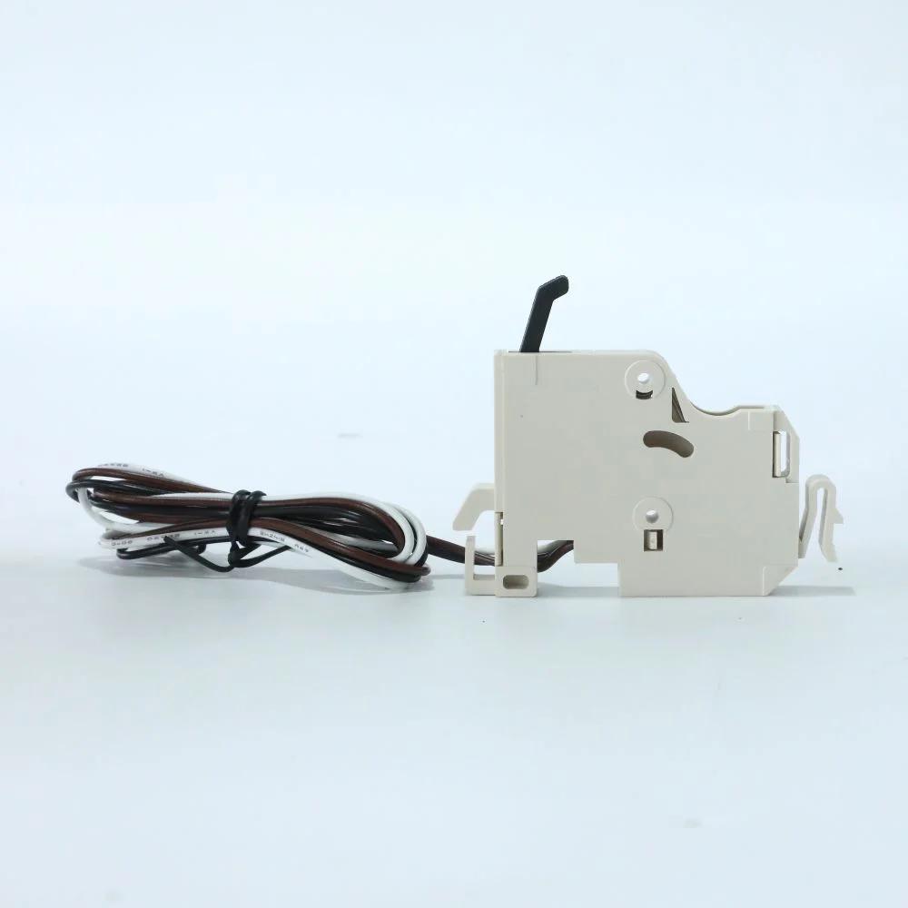
Series-pole arrangements, polarity restrictions and earthing must follow the device manufacturer’s drawing. Do not divide the bus voltage by the number of visible poles to justify a connection. A link kit, terminal accessory or permitted supply direction can be part of the rated arrangement. Substituting one of those items may require renewed approval.
IEC 60947-2 is a relevant circuit-breaker standard; IEC 60947-3 addresses relevant switch and disconnector functions. Neither a family standard reference nor a storage application label establishes the complete project’s acceptance. Identify the destination-market requirements, assembly responsibilities and necessary test evidence before comparing certification claims.
| Release check | Required record | Question if missing |
|---|---|---|
| Source duty | Voltage range, fault study and operating states | Which source condition was used? |
| Current and cable | Design calculation, derating and trip settings | What protects the conductor in this enclosure? |
| Interruption | Voltage-specific capacity and declared conditions | Does the evidence cover this DC duty? |
| 接続 | Poles, links, earthing and direction drawing | Is this the exact offered configuration? |
| 稼働開始 | Inspection, settings, appropriate tests and handover | Who releases the assembled system? |
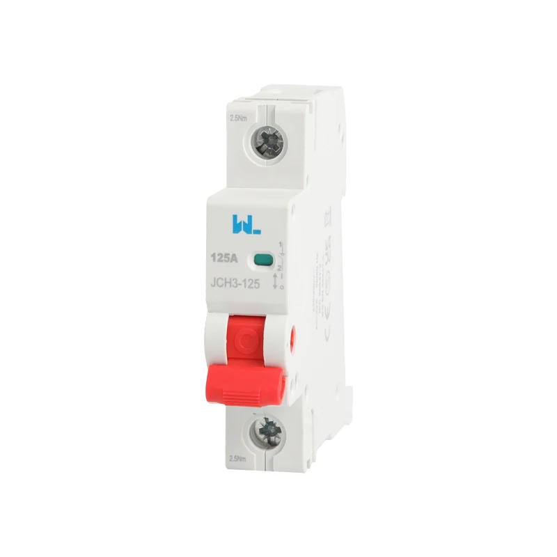
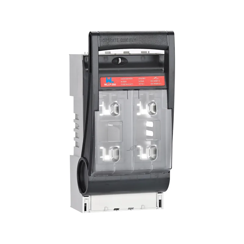
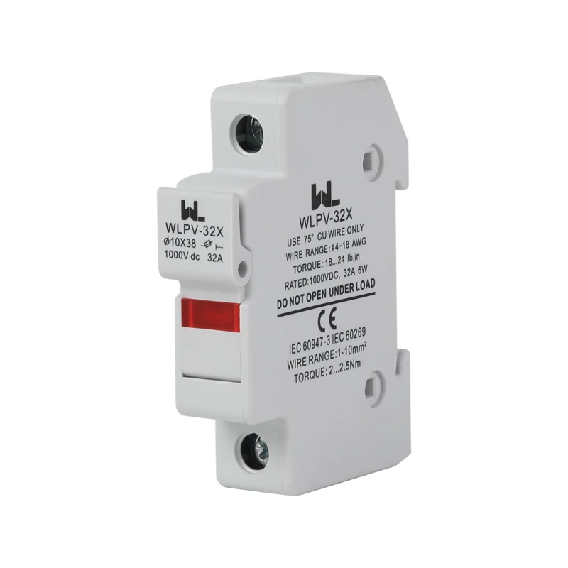
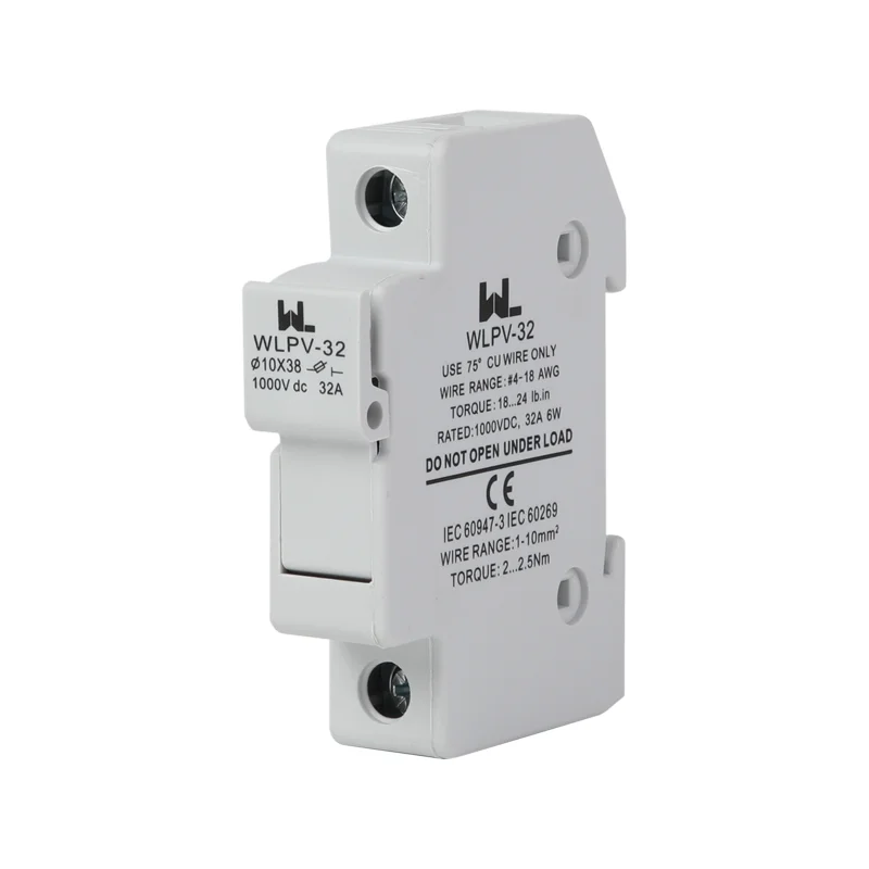
W9’s WLM7DC-400 PV DC product page supports a model-specific enquiry. Its PV designation alone does not establish battery or bidirectional suitability. Provide the storage duty and ask for an explicit confirmation supported by matching documents, rather than carrying a PV approval into a new source application.
For total project cost, compare device supply, approved links and terminals, cabinet changes, engineering, testing and maintenance access. No fixed saving follows from a particular frame size. Use the W9 product directory to identify candidates, then compare only offers that satisfy the same documented duty and scope.
よくある質問
Where can I find a DC molded-case circuit breaker manual?
Request the current manufacturer manual for the full order code. It should match the voltage, trip unit, connection and accessories being offered.
Where can I find a DC molded-case circuit breaker catalog?
Use the manufacturer catalog for initial selection, then obtain model-specific application evidence. A family overview is insufficient for battery fault-duty or reverse-current approval.
What is a DC circuit breaker?
It is a circuit breaker with declared capability to interrupt direct current under stated conditions. Its ratings must match the source, voltage and connection used in the installation.
Are DC breakers different from AC breakers?
Yes. Steady DC lacks the periodic natural current zero of AC, so a separate documented DC interruption capability is required.
Can a PV MCCB be used for battery storage?
Only when its declared application envelope covers the battery duty. Confirm source fault conditions, direction, voltage, trip behaviour and the exact connection before accepting it.
Is breaker current rating enough to size a storage circuit?
No. Voltage, fault capacity, cable protection, installation derating, poles and operating direction all require separate checks. Current arithmetic is only part of the selection.
参考文献
- Eaton: DC and PVGard Molded-Case Circuit Breakers, application overview, accessed 17 October 2026.
- ABB: SACE Tmax PV for Photovoltaic Applications, rating tables and declared configurations, accessed 17 October 2026.
- ABB: Higher-Voltage Solar Power Plant Breakers, 20 June 2018, accessed 17 October 2026.
Treat source duty as a selection input
A reliable selection connects the source-specific fault study to the exact breaker, trip unit and installed configuration. Keep voltage, current and interruption checks separate long enough to verify each one, then bring them together in a single approved schedule. Reopen that schedule when storage is added, operating direction changes or the converter is replaced. For a technical enquiry, send the source data, voltage range, duty cycle and fault assumptions through the W9 Group contact page. Request a configuration-specific response and the matching documents before ordering. The final decision should remain with the responsible project designer, who can assess the complete system rather than one device’s headline current marking.