































Compact and Reliable MCCB for Safe Low-Voltage Electrical Systems
Compact and Reliable MCCB for Safe Low-Voltage Electrical Systems
When a project engineer in Manchester accepted a compact molded-case circuit breaker for a small manufacturing line, she checked the frame dimensions, tightened the terminals and energized the panel. The feeder tripped during a motor start, and a second attempt left the enclosure warmer than expected. The rapid failure was not proof that every compact device is unreliable; the selection had ignored inrush, prospective short-circuit current and the breaker’s tested installation conditions. This article explains how to choose a compact and reliable MCCB for safe low-voltage electrical systems.
Summary: A compact MCCB is dependable only when its rated voltage, continuous current, interrupting capacity and trip settings match the complete installation. IEC 60947-2 defines key circuit-breaker requirements and tests; IEC 60364-4-43 addresses overcurrent protection in low-voltage installations. We recommend recording load, inrush, fault level, ambient temperature and conductor derating before approval, then commissioning the exact frame, trip unit and accessories. This evidence-led process usually saves more lifecycle cost than choosing by enclosure size alone.
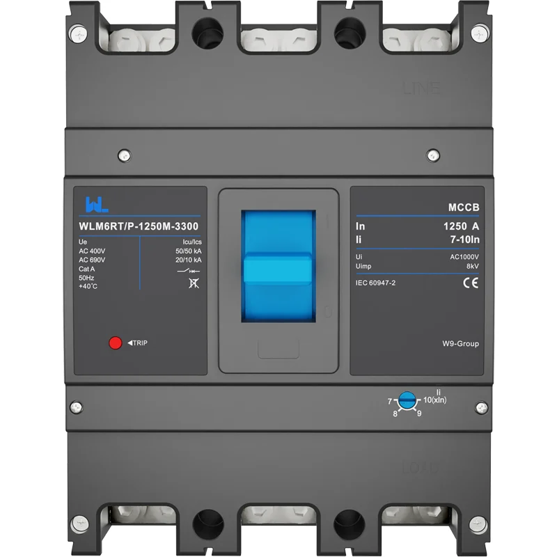
What makes an MCCB compact and reliable?
An MCCB combines switching, insulation and overcurrent interruption in a molded enclosure. “Compact” normally describes the frame and footprint; it does not guarantee a particular ampere rating, breaking capacity or temperature performance. Reliability comes from matching the device to the electrical duty and installing it as the manufacturer’s drawings show.
For a low-voltage feeder, review four data groups:
- Electrical duty: rated operational voltage (Ue), frequency, continuous current (In) and the AC or DC application.
- Fault duty: prospective short-circuit current and the declared ultimate and service capacities (Icu and Ics) at the actual voltage.
- Protection behavior: thermal-magnetic or electronic trip functions, adjustable pickups, short-time delay and any ground-fault option.
- Mechanical fit: pole count, terminal orientation, conductor size, accessory space, creepage and the enclosure’s heat dissipation.
IEC 60947-2:2020 provides the product framework, including characteristic definitions and verification tests. A 3-pole device, for example, must be evaluated with the project’s neutral and earthing arrangement; a label alone cannot establish safe isolation.
How should engineers size a compact MCCB?
Start with load and temperature data
Calculate design current from the real duty cycle, power factor and motor or transformer inrush. Compare it with conductor ampacity after correction for ambient temperature, grouping and installation method. An illustrative 230 V, 7.5 kW three-phase motor draws roughly 21 A at unity power factor before efficiency and power-factor allowances; actual starting current can be several times running current. This calculation is illustrative, not a product rating.
Compact frames can run hotter when several devices share a tight enclosure. Apply the manufacturer’s temperature-derating table and verify terminal torque. IEC 60947-2 temperature-rise tests use defined test arrangements; a crowded field panel may require a lower permissible continuous load.
Verify breaking capacity at the bus location
Estimate prospective short-circuit current from transformer impedance, conductor length and utility data. Select Icu and Ics values that are declared at the installation voltage, then check any backup or cascading table with the upstream protective device. Never copy an AC breaking value into a DC schedule: DC arc extinction, pole series arrangement and polarity are different design variables.
The honest answer is that a smaller frame may be suitable for a branch circuit while a larger frame is necessary for a feeder with high fault duty or adjustment needs. The one-line diagram, not a generic “compact” label, decides the boundary.
Coordination, selectivity and lifecycle value
Coordination means the device nearest a fault clears it first while upstream equipment remains closed. Compare time-current curves, let-through energy and short-time withstand for every protective layer. A configurable trip unit can help separate a feeder from downstream MCBs, but an adjustment cannot compensate for insufficient interrupting capacity or undersized conductors.
Commissioning is part of reliability. Record the breaker identification, trip-dial positions, calculated pickups, torque values and test instruments. Use a calibrated primary- or secondary-injection test method allowed by the trip-unit instructions; repeat the test after a major setting change. These records shorten troubleshooting and support handover under IEC 60364 verification practices.
| Decision dimension | Compact MCCB approach | Potential trade-off | Evidence to request |
|---|---|---|---|
| Panel space | Smaller footprint and shorter bus runs | Less room for cable bending and heat dissipation | Outline drawing, terminal layout and clearance data |
| Protection | Thermal-magnetic or electronic trip in one enclosure | Settings may be limited by the selected frame | Time-current curves and setting range |
| Fault duty | Declared Icu/Ics for the application | Higher fault levels may require a larger frame or tested backup | Model-level test report and coordination tables |
| Maintenance | Resettable device with visible handle and accessories | Incorrect torque or dust can raise contact resistance | Installation guide, torque schedule and inspection plan |
| Total cost | Less copper, enclosure volume and labor when correctly sized | Rework costs rise if derating or selectivity is missed | Approved calculation and as-left commissioning record |
Where do compact MCCBs fit best?
Application conditions determine whether a compact frame is an advantage. The following matrix keeps the decision tied to the circuit rather than to a marketing category.
| Application | Typical design question | Useful MCCB feature | Project check |
|---|---|---|---|
| OEM machine panel | Will motor inrush cause nuisance trips? | Adjustable instantaneous or short-time settings where provided | Motor-start curve, control voltage and enclosure temperature |
| Commercial distribution board | Can a downstream fault remain local? | Coordination-friendly trip curve and auxiliary contacts | Selectivity study and local installation code |
| Photovoltaic or battery feeder | Is the device tested for DC voltage and polarity? | Declared DC utilization, pole series arrangement and DC Icu | IEC 60947-2 data, array or battery fault study |
| Process retrofit | Can future load growth be accommodated? | Adjustable long-time pickup within the approved frame | Recheck cable ampacity, heat and fault level after expansion |
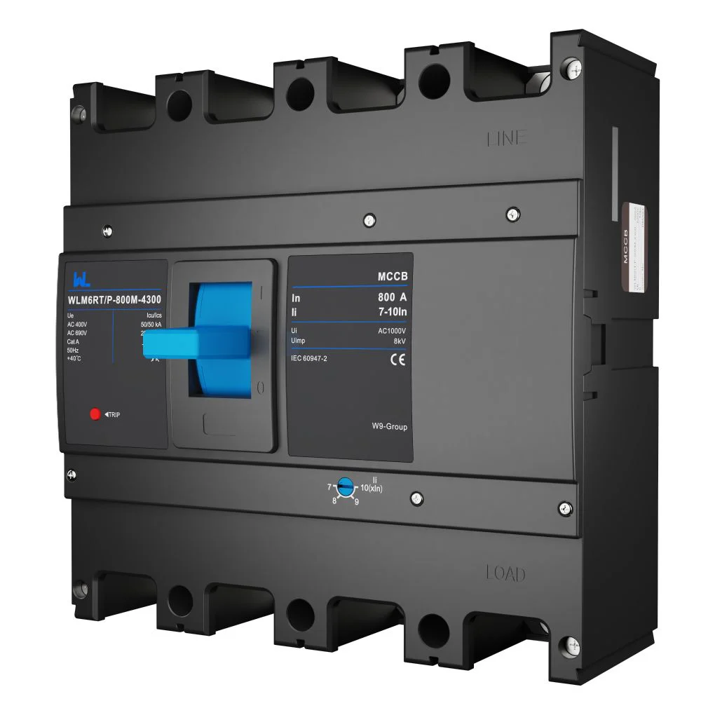
Standards and compliance that protect the project
IEC 60947-2 covers low-voltage circuit-breakers used in switchgear and controlgear, including performance characteristics and type tests. IEC 60947-1 supplies common definitions and general rules. For installation design, IEC 60364-4-43 addresses protection against overcurrent. In the United States, UL 489 may apply to molded-case circuit breakers, while NFPA 70 (National Electrical Code) governs installation; these are different conformity routes.
A standard reference is not a blanket certification. Ask for the exact frame, trip unit and accessory combination, applicable edition, declaration, test report, temperature-rise data and wiring diagram. Unsupported claims can delay inspection, invalidate a panel listing or trigger expensive field replacement. The destination market, end use and authority having jurisdiction determine which documents are required.
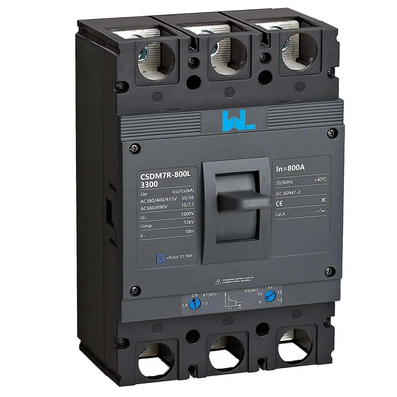
Selection checklist and W9 Group sourcing option
- Freeze the one-line diagram, load schedule, conductor sizes, ambient conditions and prospective fault current.
- Choose AC or DC duty, poles, Ue, In, Icu/Ics and trip technology from the model datasheet.
- Check dimensions, terminals, creepage, accessory wiring and enclosure heat before releasing the panel layout.
- Run coordination and backup checks with manufacturer curves; document settings and test limits.
- Commission with calibrated instruments and retain the as-left record for maintenance.
W9 Group (Zhejiang W9 Group Technology Co., Ltd.), established in 2020, describes a China-based low-voltage protection portfolio that includes MCCBs and related MCB, RCCB, RCBO, SPD and AFDD devices, with testing and OEM/ODM support. Buyers should verify the exact model and destination-market evidence. The WLM6RT MCCB product page can be a starting point for configuration review; request current drawings and test documents before approval.
Frequently asked questions
What is a compact MCCB?
It is a molded-case circuit breaker designed to provide switching and overcurrent interruption in a relatively small frame. “Compact” describes physical format, not a universal current or fault rating. Confirm the model’s declared ratings and clearances for the installation.
Are compact MCCBs reliable for industrial feeders?
They can be, when voltage, load, fault duty, temperature and coordination are verified against the manufacturer’s tests. Reliability falls quickly when a compact enclosure is overloaded thermally or the breaker’s Icu is below the prospective fault current. Commission the installed configuration.
How do I size an MCCB for a motor?
Calculate running current, starting current, conductor ampacity and prospective fault current; then select a trip curve that avoids nuisance operation while still protecting the conductor. Use the motor manufacturer’s data and verify coordination with downstream devices. Local code and installation method can change the result.
Can an AC MCCB be used on a DC circuit?
Only if the exact device is tested and marked for the DC voltage, polarity and pole arrangement. DC arcs do not have the same natural zero crossing as AC arcs. Use the manufacturer’s DC rating table and wiring diagram, not the AC catalogue column.
What documents should a buyer request?
Request the datasheet, outline and terminal drawings, trip curves, Icu/Ics evidence, temperature-derating information, accessory diagram and applicable declarations or certificates. Confirm the model number and standard edition match the project. Keep the final setting and test record with the panel file.
References
- International Electrotechnical Commission standards catalogue (IEC 60947-2 and IEC 60947-1).
- IEC 60364 installation standards catalogue, including overcurrent-protection requirements.
- NEMA molded-case circuit-breaker standards overview.
- NFPA 70, National Electrical Code.
The difference is not the smallest frame on the shelf—it is the discipline that makes ratings, conductors and coordination agree. Review W9 Group’s low-voltage protection products, compare the documented MCCB configuration with your one-line diagram, and contact the W9 team with the load schedule and destination standard before procurement is locked.