






The Ultimate Guide to Circuit Breakers and Their Advanced Trip Devices
A breaker with a sophisticated display can still be commissioned against the wrong protection study, sensor configuration or supply scenario. More settings do not solve that mismatch. For a panel builder or operator, the useful question is how the sensing, protective decision and opening mechanism are connected to the actual system—and how that chain will be verified and controlled after handover.
Quick answer: An advanced trip unit is useful only when its functions match a documented protection need. Electronic units may support long-time, short-time, instantaneous and ground-fault functions, known as L, S, I and G; availability varies by model. Derive settings from the design and manufacturer data, not a generic example. Secondary injection can verify specified release behaviour but does not prove every part of the primary sensing and interruption chain. Select a test plan that states what was actually checked and what remains outside its scope.
Circuit Breaker Protection Components
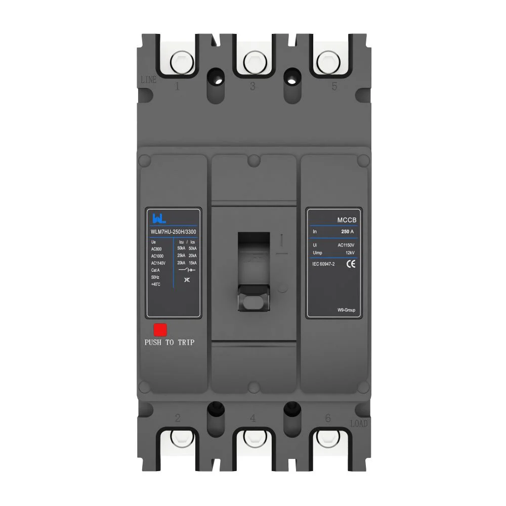
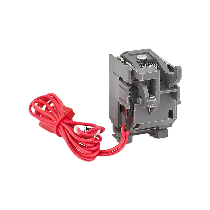
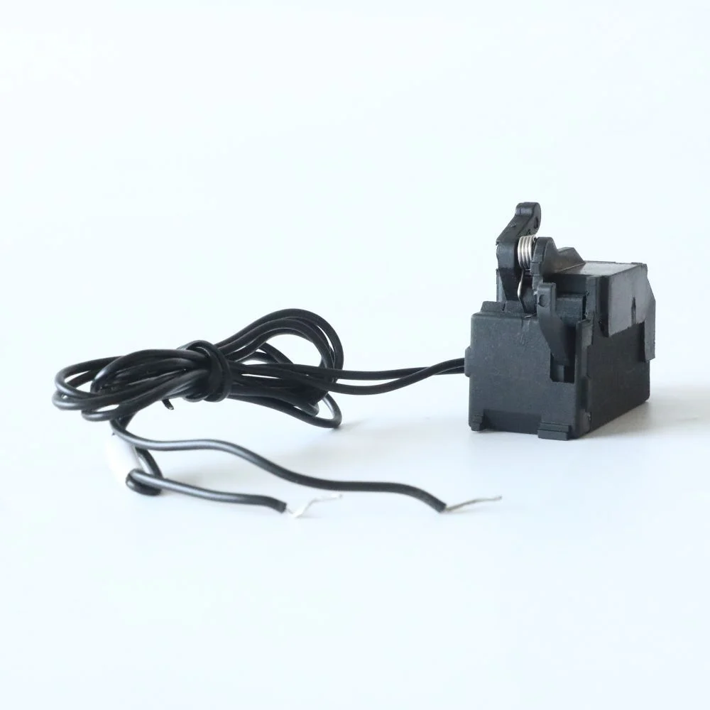
A breaker must carry normal load and interrupt faults within its rating. Its trip system senses a condition, decides whether opening is required and operates the mechanism. Electronic releases add configurable logic, but their behaviour depends on the exact sensor, rating arrangement, firmware or configuration where applicable, and supported functions.
Frame size, sensor rating, plug or equivalent rating configuration, and approved pickup settings can describe different limits. Record the identifiers required by the manufacturer instead of assuming every component in a frame has the same rating. A replacement release or sensor can change the approved setting basis even if the breaker housing remains unchanged.
Displays, communications and protective operation can have separate power requirements. A dark display is not sufficient evidence that protection has failed, just as a live display is not proof that the trip chain is correct. Verify the release’s operating conditions and accessory supply in its instructions; do not generalise across electronic designs.
Thermal-Magnetic vs Electronic Releases
Thermal-magnetic protection combines a time-dependent overload response with magnetic operation for higher current conditions. It can be suitable where its published characteristic meets the duty without needing additional functions. Electronic protection can offer additional adjustment or information where those capabilities are documented and justified by the system.
Neither is universally superior. A straightforward feeder may not benefit from extra options if the fixed curve already satisfies the design. A more complex distribution arrangement may need configurable delays, source-scenario review and event information. In both cases, rating and coordination evidence matters more than the number of buttons on the release.
| Function | Protective purpose where provided | Input needed for selection | Common mistake |
|---|---|---|---|
| L — long time | Overload protection | Load, conductors and applicable thermal limits | Raising pickup solely to remove unexplained trips |
| S — short time | Short-circuit response with configured delay | Coordination and equipment withstand | Adding delay without checking fault-energy consequences |
| I — instantaneous | Operation without an intentional time delay | Fault levels, inrush and device characteristics | Assuming disabling it always improves the design |
| G — ground fault | Ground-fault function within the declared arrangement | Earthing system, sensing configuration and protection objective | Treating it as equivalent to any required personal-protection RCD |
Engineered Trip Settings
A selective delay must remain within the system’s withstand limits. Review the breaker rating, assembly capability, conductor limits and fault-clearing objectives together. A high breaking-capacity figure does not independently justify a delayed trip under every prospective fault condition.
Review utility and generator operating conditions separately where they change the available current. Both maximum and minimum fault conditions can matter: the device needs adequate interrupting capability, while its characteristic must still operate appropriately in the lower-current scenario. Copying another facility’s LSIG settings does not establish either requirement.
For an electronic MCCB enquiry, request curves and settings data for the exact offered configuration. Manufacturer selectivity or backup tables can provide useful evidence, but their stated combinations and limits must match the proposed devices. A family name or a graphic overlay without the actual conditions is insufficient.
Primary vs Secondary Injection Testing
A successful secondary-injection test does not verify the whole primary current path. It applies a defined test signal to the release or protective device through an approved arrangement. It can check particular functions and, where the procedure provides it, operation of the breaker; it does not automatically verify primary sensors, their connections or actual fault interruption.
Primary injection sends test current through the relevant primary arrangement. Its scope and practical limits depend on the equipment and test plan. It is not simply a mandatory extra step invented for every product, nor is an in-service field test a reproduction of the manufacturer’s full short-circuit rating test.
| Check | What it may establish | What it does not establish by itself | Record needed |
|---|---|---|---|
| Secondary injection | Specified release response and supported trip-chain operation | All primary sensing connections or rated fault interruption | Kit, configuration, functions and pass criteria |
| Primary injection | Response through the tested sensing and operating arrangement | Every possible installation condition or product certification | Current, timing, connection scope and limitations |
| Mechanical functional check | Operation of specified mechanisms and auxiliaries | Calibration of all protective functions | Operating procedure and observed results |
| Settings verification | Agreement with the approved study and configuration | Physical health of all contacts and conductors | As-found/as-left values and study revision |
Schneider Electric’s public FAQ on its Full Function Test Kit explains these distinctions and notes that both methods require specialist knowledge. It describes secondary injection as normally performed without current through the main poles and acknowledges that the whole system is not tested by that method. This is manufacturer guidance, not a universal test-kit procedure for W9 equipment.
Do not disconnect sensing circuits or attach an unspecified test set as an experiment. Testing can create hazards or leave protection in an altered state. Use qualified personnel and the exact approved procedure, including restoration and verification before equipment returns to service.
Breaker Lifecycle Change Control
An advanced unit can preserve useful information only if the site knows which settings and records are authoritative. Retain the study revision, device identifiers, approved values, commissioning results and responsible change authority. A firmware, sensor, accessory or supply change may need a documented review rather than an informal reset.
The ACB configuration guide is relevant when the release is part of a larger power-breaker arrangement. Protection settings, mounting and control accessories are separate dimensions; a drawout cradle does not prove that the electronic release has the functions needed for the study.
For lifecycle cost, compare the release and test equipment, engineering, training, configuration management and likely service consequences using project data. Do not claim an automatic return on investment from electronics or a guaranteed reduction in trips. Better information creates value only when it supports a defined operating or maintenance decision.
Product and Commissioning Evidence
IEC 60947-2:2024 provides the industrial breaker product scope within its voltage limits. UL 489 and UL 1066 address different product categories for projects using those approval routes. None of those references alone proves a supplier’s device is certified or that an installed protective arrangement has been commissioned.
- Identify the device, sensor and release configuration.
- Select only functions justified by the load and protection study.
- Check coordination and fault/withstand duty across supply scenarios.
- Approve a test plan with explicit coverage and limits.
- Record settings, restoration checks and future change control.
W9 Group can be considered for model-level circuit-protection enquiries. Use its technical-support documentation route to request supported trip functions, configuration details, curves and approved testing information rather than assuming every electronic breaker provides LSIG, communications or event logging.
Frequently asked questions
What are advanced trip devices?
They are protection releases offering capabilities beyond a basic fixed characteristic, such as configurable sensing or response and optional diagnostics. Exact functions must be confirmed for the selected model.
Does every electronic breaker have LSIG?
No. Some functions may be absent or depend on the offered configuration. Require a function schedule and the appropriate curves rather than assuming the acronym applies.
Can I copy LSIG settings from a similar installation?
No. Load, conductors, fault contribution, earthing and downstream devices can differ. Approved settings must come from the actual design and exact manufacturer data.
Does secondary injection prove the complete breaker works?
No. It proves only the functions and trip-chain elements covered by the approved test arrangement. Primary sensing, physical condition and fault interruption have separate evidence requirements.
Is an industrial ground-fault function the same as personal-protection RCD sensitivity?
Not automatically. The sensing, threshold, purpose and installation requirements can differ. Verify the required protection objective and device scope separately.
References and conclusion
- IEC 60947-2:2024 — industrial circuit-breaker public scope.
- Schneider Electric FAQ FA279642: Primary versus secondary injection — last modified 24 September 2025; manufacturer-specific test explanation.
- UL 489 active public scope — moulded-case breaker category.
- UL 1066 active public scope — power-breaker category.
References were checked on 14 October 2026. Document what the protection does and what the test actually proves. Contact W9 Group with the configuration, study requirements and commissioning evidence needed for the project.