



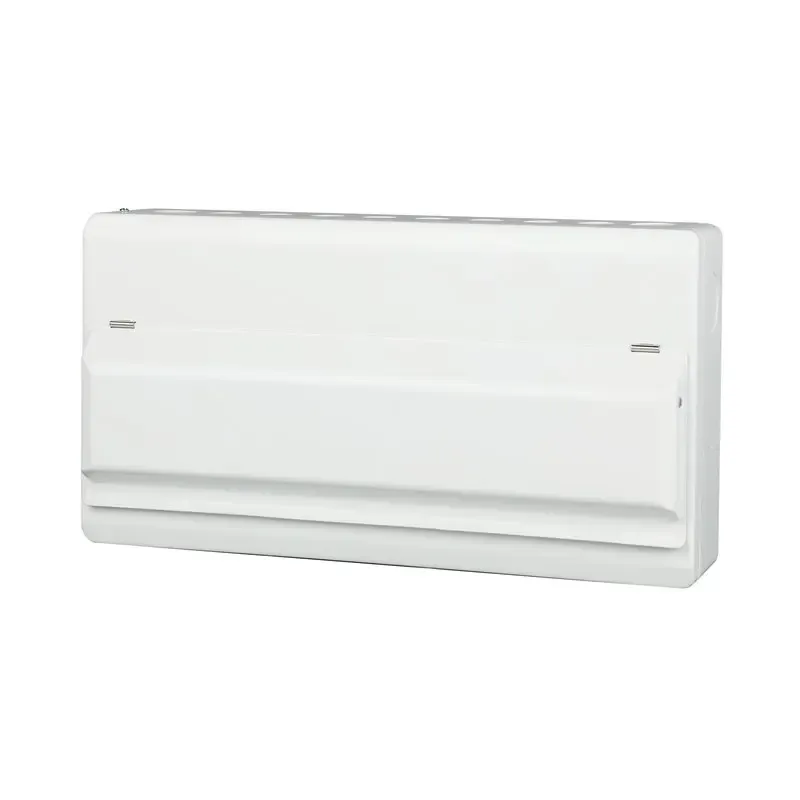





1P+N MCB: A Compact Circuit Breaker for Modern Electrical Safety
A compact 1P+N MCB can fit a single-phase board while opening the line and neutral together, but the shorthand does not describe every internal arrangement. Before replacing a tripping device, verify which pole is protected, how the neutral opens and whether the circuit also needs residual-current protection. A rail-compatible replacement can still be wrong for the wiring scheme.
Summary: A 1P+N MCB normally protects one line conductor and switches the neutral in the same operating movement. It is different from a 1P breaker and from a 2P breaker that may protect both poles. The exact product diagram controls neutral timing, protection and terminal use. Select rated current, curve, voltage and breaking capacity from the load, cable and fault study, then check the destination-market product and installation rules. An MCB does not provide residual-current protection unless the device is an RCBO.
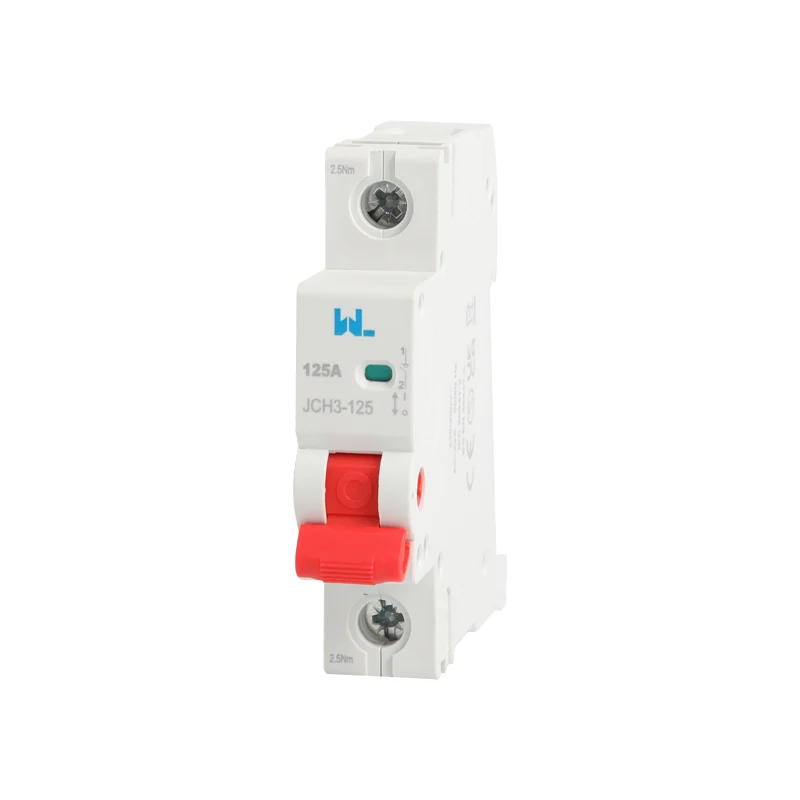
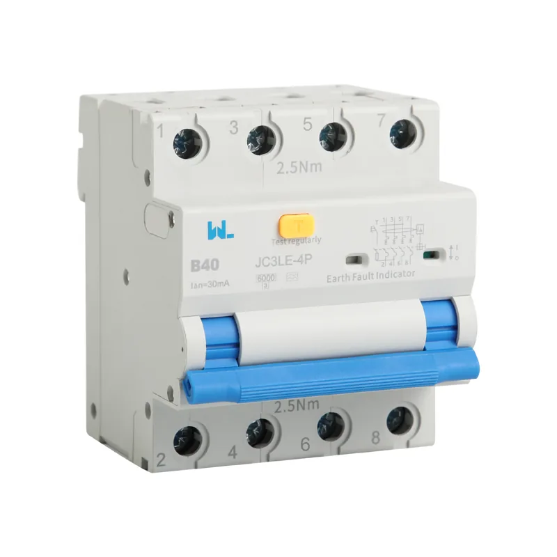
A 1P+N device often occupies two module positions and combines one protected line pole with a switched neutral pole. Some families protect only the line while others provide protection or switching arrangements defined by their product standard. Do not infer the function from “2P” printed on a catalogue page. Read the pole diagram, terminal markings and test scope for the exact model before wiring.
Pole Configuration and Neutral Switching
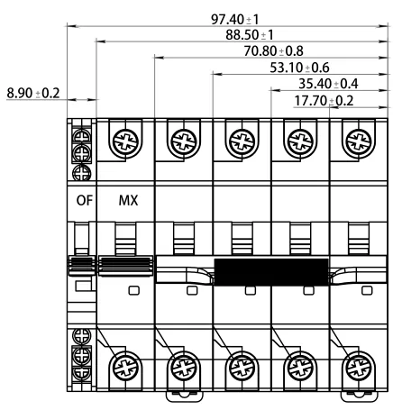
A single-pole MCB interrupts the line only. It can protect a branch circuit, yet the neutral remains connected when the handle is off unless a separate isolator is provided. A true two-pole MCB has overcurrent releases in both poles. A 1P+N model normally combines one protected line pole with a switched neutral, preserving compactness while allowing both conductors to be isolated for service. The exact neutral switching sequence and whether the neutral is protected must be confirmed in the data sheet.
| Configuration | Typical function | Neutral behavior | Procurement check |
|---|---|---|---|
| 1P | Overload and short-circuit protection on one line | Usually not switched | Provide a separate neutral bar or isolator where required |
| 1P+N | Line protection with linked two-conductor disconnection | Switched; protection depends on model | Read pole diagram, terminal markings and test scope |
| 2P | Overcurrent protection on two poles | Neutral may be protected or treated as a second phase | Confirm suitability for the supply system and neutral conductor |
| RCBO 1P+N | Overcurrent plus residual-current protection | Line and neutral pass through the sensing path | Use IEC 61009-1 data and test the RCD function separately |
For a broader device-family comparison, the site’s circuit breaker guide explains where MCBs, RCCBs and RCBOs differ. A 1P+N MCB does not detect earth leakage by itself; add an RCCB or select an RCBO when the design requires residual-current protection.
Verify Neutral-Pole Operation
Use a three-line acceptance note for every 1P+N order: protected pole, switched pole and opening sequence. Check whether the neutral contact is rated only for switching or carries an overcurrent release, and verify the manufacturer’s restriction on line and neutral orientation. This prevents a 1P+N device from being treated as a fully protected 2P breaker. If the circuit requires residual-current protection, the external RCCB or RCBO must be included in the same coordination review.
Ratings and Fault-Duty Verification
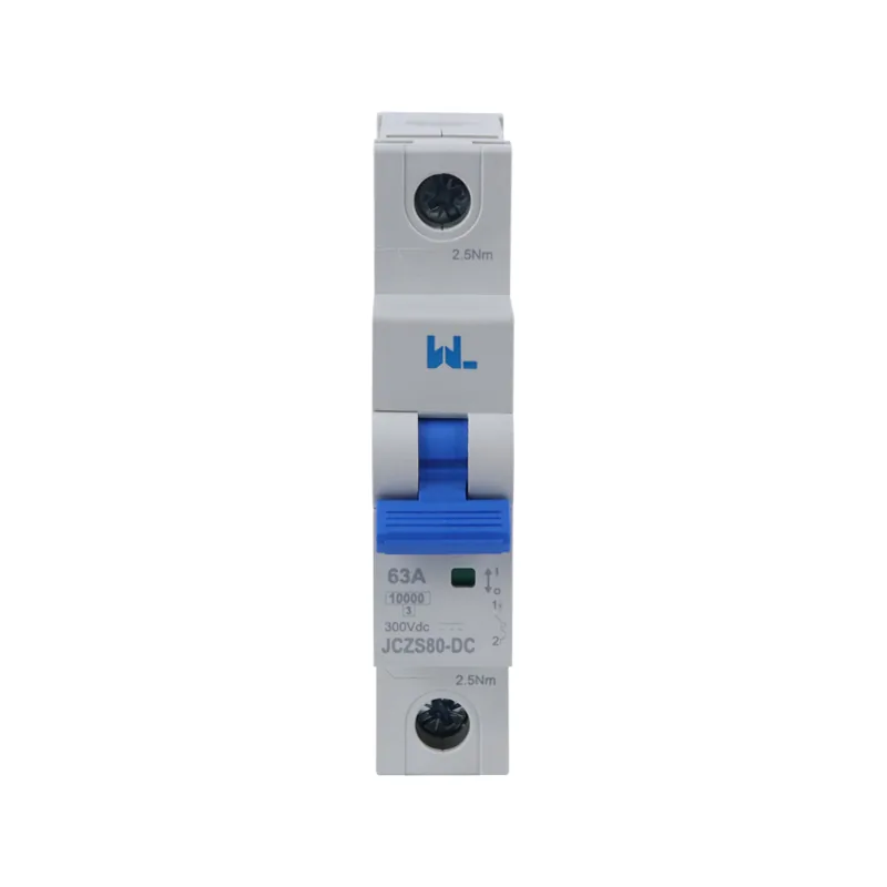
Start with the design current, not the available space. For an illustrative 230 V, 2.3 kW heater, I = P/V = 2,300/230 = 10 A. A 10 A device could be considered only after checking conductor ampacity, ambient temperature, installation method, grouping and duty cycle. IEC 60364-4-43 principles require the protective device to coordinate with the cable; a breaker that is physically convenient but electrically oversized can allow damaging conductor heating.
Trip curves describe the tested magnetic operating band and are not a universal nuisance-trip fix. B, C and D labels must be read with the applicable product standard and the minimum fault current at the far end of the circuit. A D curve chosen only to tolerate inrush can delay magnetic operation when impedance is high. Confirm starting current, cable protection and time-current data together; the B, C and D curve explanation shows how to read the time-current envelope.
Breaking capacity is separate from the curve. If the measured prospective short-circuit current at the board is 4 kA, the marked Icn (or the applicable industrial Icu/Ics values) must cover that duty with any specified backup fuse. On long feeders, calculate the minimum fault current as well as the maximum: a high-threshold D curve may fail to trip magnetically when impedance is high. Keep the calculation, manufacturer time-current curve and coordination table in the project file.
Check the Fault-Current Range
Breaking capacity must cover the maximum prospective fault current at the board, while the selected curve must still clear the minimum fault current at the remote end within the required time. Keep both calculations with the cable ampacity and inrush basis. A convenient 10 A example cannot determine a general 1P+N rating, and a higher curve does not compensate for an undersized conductor or an unverified neutral arrangement.
Applications and Wiring Limits
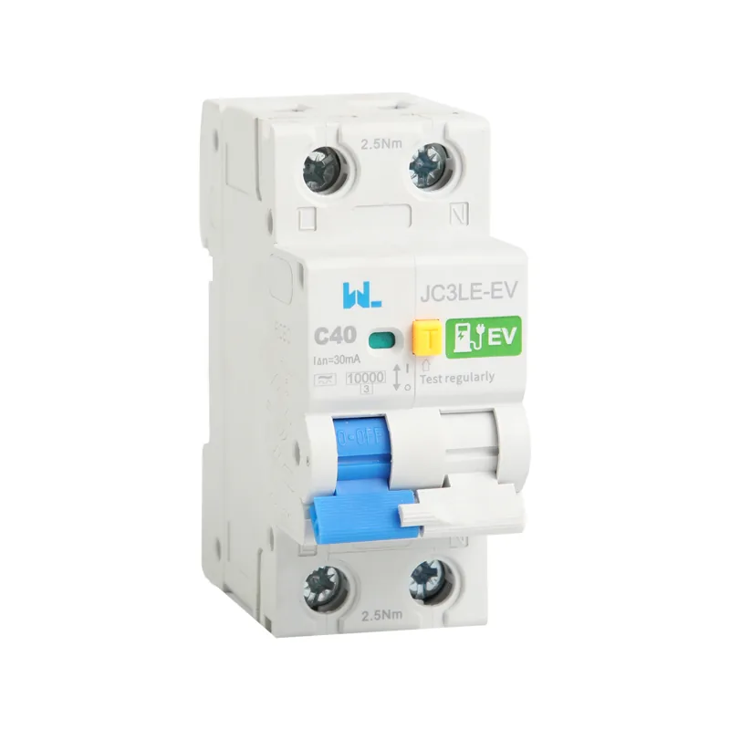
The compact arrangement is useful in single-phase homes, offices, retail fit-outs and small control panels where simultaneous line-neutral isolation improves service safety without the width of a full two-pole protected breaker. It can also simplify retrofit schedules when the existing board has limited module capacity. The benefit is operational, not a license to ignore wiring rules: a neutral that is undersized, shared incorrectly or interrupted out of sequence remains a hazard.
| Application | Why 1P+N helps | Evidence to request | Common pitfall |
|---|---|---|---|
| Residential final circuit | Line protection with clear isolation for maintenance | Rated current, curve, Icn and neutral switching diagram | Assuming a 1P+N label means residual-current protection |
| Office socket or lighting board | Two-conductor disconnection in a narrow modular layout | Inrush assessment, cable calculation and torque values | Selecting a D curve to cure nuisance trips without fault-current review |
| Small HVAC or pump feeder | Compact feeder protection where starting current is known | Motor starting data, TCC and selectivity table | Ignoring restart inrush or upstream RCCB compatibility |
| Control or OEM panel | Consistent pole arrangement across exported builds | Declaration, test report and destination-market standard | Transferring a certificate from another frame or rating |
For residual-current protection in the same footprint, an RCBO may be the better choice. The site’s RCBO function article explains why overload and leakage duties should be coordinated rather than assumed to be interchangeable.
Commissioning and Handover Records
IEC 60898-1 covers circuit-breakers for overcurrent protection in household and similar AC installations, including construction, ratings and verification tests. IEC 60947-2 addresses low-voltage circuit-breakers in switchgear and controlgear, often with industrial utilization categories and different test assumptions. IEC 60364-4-43 is an installation-design reference for overcurrent coordination; it is not a product certification. Where an RCBO is specified, IEC 61009-1 addresses residual-current circuit-breakers with integral overcurrent protection.
Destination-market rules still apply. In North America, UL 489 covers branch and feeder circuit breakers, while UL 1077 covers supplementary protectors inside equipment; one listing cannot be casually substituted for the other. A CE mark, UL listing or other declaration must match the exact model, pole arrangement, voltage and interrupting rating. Unsupported certification language can delay a submittal, trigger redesign or create warranty exposure.
During installation, follow the maker’s line/load and torque instructions, keep the neutral on the intended bar and label the circuit schedule. Verify continuity, polarity, insulation and prospective fault current with the required method; an RCD or RCBO test is separate from an MCB functional check. After an interruption, inspect terminals and replace a device that has exceeded its tested duty.
1P+N Procurement Checklist
- Record supply voltage, frequency, earthing system, phase, neutral arrangement and number of poles.
- Calculate design current and cable ampacity with ambient and grouping derating; do not size from module width.
- Compare measured inrush with the exact B/C/D time-current curve and verify disconnection at minimum fault current.
- Confirm Icn or Icu/Ics, terminal capacity, busbar compatibility, polarity and the neutral switching sequence.
- Request the declaration, test reports, wiring diagram, installation torque and destination-market instructions; retain them with commissioning records.
W9 Group (Zhejiang W9 Group Technology Co., Ltd.) supplies low-voltage protection products and documentation support for OEM and panel projects. Treat that support as a sourcing input, not design approval. Confirm the exact 1P+N model, pole behavior, ratings and test scope before adding it to a bill of materials. Review the circuit protection products range when preparing the bill of materials.
Frequently Asked Questions
What does 1P+N mean on a circuit breaker?
It identifies one line pole plus a neutral pole in a single modular device. The line usually carries the thermal-magnetic release, while the neutral is switched or linked; the manufacturer’s diagram confirms whether the neutral is protected.
Is a 1P+N MCB safer than a 1P MCB?
It can provide more complete isolation because line and neutral open together, which helps maintenance on a single-phase circuit. It is not automatically safer if the neutral sequence, ratings or wiring are wrong, and it does not provide earth-leakage protection.
Can a 1P+N MCB protect against electric shock?
An MCB responds to overload and short-circuit current, not ordinary leakage through a person. Use an RCCB or RCBO with the correct sensitivity and installation rules when residual-current protection is required.
What rating should I choose for a 1P+N breaker?
Select rated current and curve from the calculated load, conductor ampacity, inrush and fault current. Then confirm the marked breaking capacity, voltage and pole arrangement against the applicable standard; a 10 A example cannot be copied to every 230 V circuit.
Does a 1P+N MCB switch the neutral?
Most 1P+N devices are designed to switch the neutral with the line, but the timing and whether the neutral has overcurrent protection vary. Check terminal labels and the manufacturer’s wiring instructions before installation or replacement.
Technical References
- CHAC Electric — 1P+N vs 2P MCB: Key Differences for Single-Phase Circuits. Google result observed 17 October 2026; direct article was not used as a verified full-text source, so model-specific claims remain conditional.
- OSHA 29 CFR 1910.303 — General. U.S. workplace requirements for suitability, interrupting rating and coordination; not a global wiring code. Accessed 17 October 2026.
- IEC 60898-1 — Circuit-breakers for household and similar installations. Product-standard reference identified during research; exact edition and applicability must be checked for the project. Accessed 17 October 2026.
The compact breaker earns its place when every pole has a documented purpose: protect the conductor, isolate the circuit and coordinate with the devices around it. W9 Group’s low-voltage protection range can support that evidence-led review; contact the technical team with the load schedule, fault level and destination market before the panel is released.