































Переключатель MCCB3P с функциями защиты от перегрузки и короткого замыкания
When a facilities engineer in Monterrey reviewed a quotation for a three-phase packaging line, he selected a compact three-pole breaker, copied the nominal motor current onto the order, and expected an easy start-up. The breaker tripped during the first production shift; a second unit ran hot at a loose terminal. The root cause was not a defective product. The specification had ignored overload time, prospective short-circuit current, and the need to protect all three phases together. That is why buyers ask what an MCCB3P circuit breaker with overload and short-circuit protection functions actually does, and how to specify one correctly.
Buyer check: What should a buyer verify before selecting moulded case circuit breaker? Start with the actual electrical duty: rated current, operating voltage, poles, Icu/Ics, thermal/magnetic or electronic settings, ambient derating and coordination. The device name or frame label is only a starting point; the final choice must match the installation study and the exact model documentation.
Резюме: A 3-pole molded-case circuit breaker (MCCB) combines an inverse-time overload release with a magnetic or electronic short-circuit release, opening all phase poles when a fault is detected. Select the frame, continuous current, interrupting capacity and trip settings to match the installation—not just the load label—and verify the design against IEC 60947-2 (or the applicable national adoption). A coordination study and a documented test schedule usually cost less than one nuisance shutdown.
What the three poles protect
“3P” means three current-carrying poles operated by one mechanism. In a typical 400 V, 50 Hz motor feeder, the breaker sits upstream of a contactor, overload relay or variable-speed drive. Opening all three poles isolates the phase conductors together, preventing a motor from continuing on two phases. IEC 60947-2 treats the device as a circuit-breaker for low-voltage distribution and specifies verification of temperature rise, dielectric strength, operating characteristics and short-circuit performance.
The breaker does not replace every protective function. A residual-current device is still needed where earth-leakage protection is required, and a motor starter may need separate overload, control and emergency-stop components. The MCCB’s job is selective interruption of excessive phase current while maintaining the required service continuity.
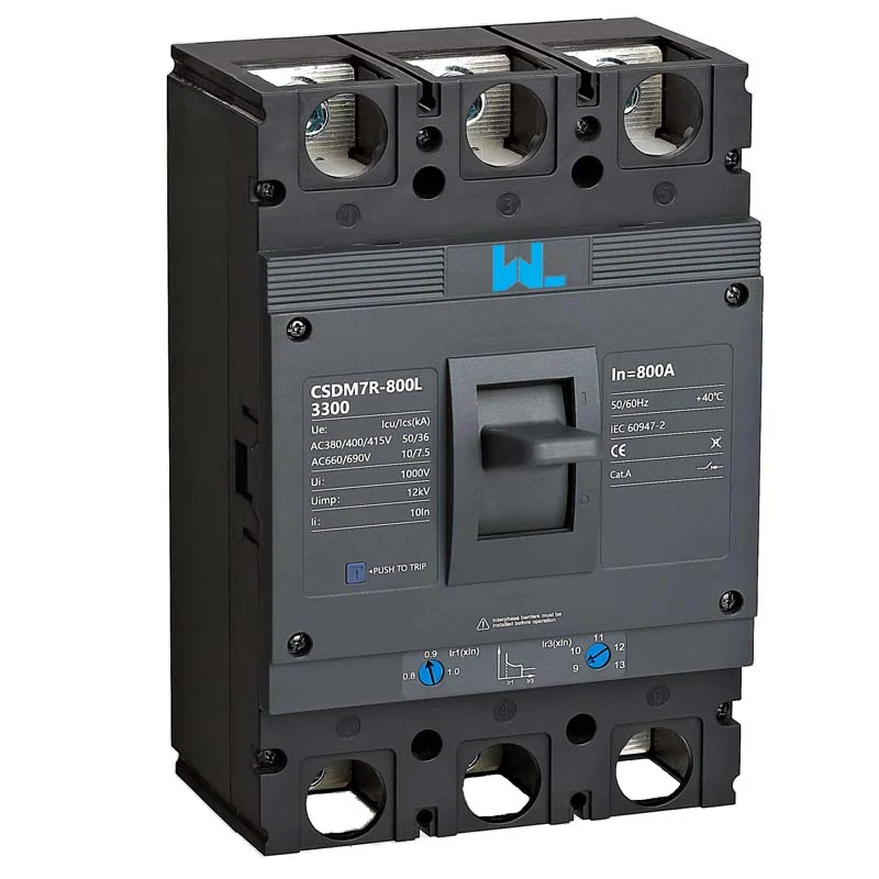
How overload and short-circuit releases work
Application check: When is moulded case circuit breaker the right fit? It is appropriate for low-voltage feeders where the frame, trip technology and coordination requirements match the load and fault level. Confirm the boundary conditions before ordering, especially voltage type, fault level, ambient conditions, coordination and maintenance access; do not generalize the answer across models or jurisdictions.
Overload protection is time dependent
An overload is a sustained current above the cable or equipment design value—for example, a conveyor motor carrying more product than planned. A thermal bimetal or electronic long-time element responds with an inverse-time curve: a modest overcurrent takes longer to trip, while a larger one trips faster. IEC 60947-2 uses defined current levels and time bands for these tests; the exact curve and tolerances belong to the selected trip unit. Engineers should set the long-time pickup below the conductor ampacity and above the normal operating current, allowing for documented starting inrush.
Short-circuit protection is instantaneous
A phase-to-phase or phase-to-ground short circuit can reach kiloampere levels in milliseconds. The magnetic element (or the instantaneous region of an electronic trip) drives the mechanism without waiting for thermal heating. The interrupting rating, expressed as Icu и яcs under IEC 60947-2, must be no lower than the calculated prospective fault current at the installation point. Icu is the ultimate breaking capacity; Ics is the service breaking capacity after which the breaker is expected to remain serviceable under the standard test sequence.
For example, if a panel calculation gives 18 kA prospective current, a 25 kA-rated breaker provides a design margin; a 10 kA device does not. This is an illustrative selection check, not a substitute for a short-circuit study or the manufacturer’s tested combinations.
Three-Pole MCCB Rating Requirements
Start with the system voltage and earthing arrangement, then record the continuous load current, conductor size, ambient temperature and enclosure conditions. A 3P breaker may be available with fixed or adjustable current settings; adjustment cannot increase the frame’s certified interrupting capacity. Derating can apply above the reference ambient (often 40 °C in product standards), in a crowded enclosure, or when several devices carry load side by side.
- Ue and frequency: verify the rated operational voltage and AC frequency for the destination network.
- In / Ir: coordinate the frame and long-time setting with cable ampacity and expected load; never use the dial as a reason to oversize conductors.
- Icu и яcs: compare both with the prospective short-circuit current and the project requirement for post-fault service.
- Terminal and accessory limits: confirm lug torque, conductor range, shunt trip, auxiliary contact and undervoltage-release compatibility.
IEC 60947-1 provides common definitions and general rules, while IEC 60947-2 supplies the circuit-breaker-specific tests. In North America, UL 489 covers molded-case circuit breakers; certification marks and installation rules remain market- and product-specific.
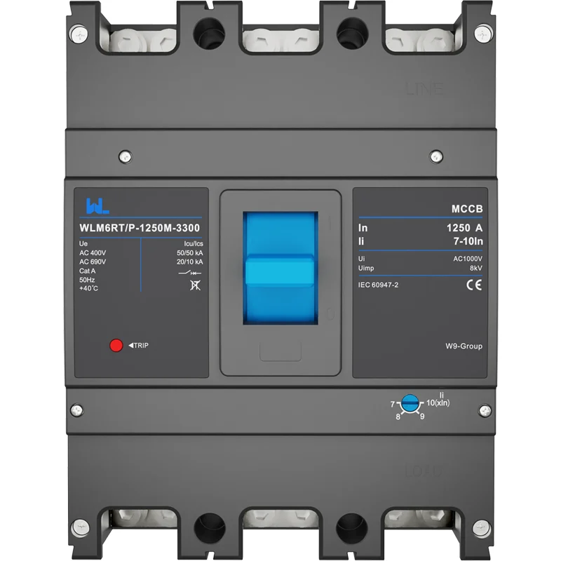
Fixed vs Adjustable Three-Pole MCCBs
| Размер решения | Fixed thermal-magnetic 3P MCCB | Adjustable or electronic-trip 3P MCCB |
|---|---|---|
| Protection setting | Factory-set long-time and instantaneous values; simple to apply. | Field-selectable ranges; supports staged coordination when documented. |
| Ответственность за нарушение правил | Choose a tested Icu/Ics combination for the installation. | Same breaking-capacity obligation; electronics do not increase Icu. |
| Ввод в эксплуатацию | Visual and torque checks plus functional trip test. | Add setting verification, injection or manufacturer-approved test procedure. |
| Up-front cost tendency | Usually lower for standard feeders. | Usually higher, offset when one frame can serve varied loads. |
| Total cost of ownership | Fewer settings to misconfigure; limited flexibility after a load change. | Better adaptability, but requires records, trained technicians and periodic review. |
The honest answer is that neither type is universally better. A stable lighting feeder may benefit from a fixed trip, while a process plant with 30–100% load variation can justify adjustment when coordination and maintenance resources are available.
Application and performance matrix
| Заявление | Typical design question | Документы для запроса |
|---|---|---|
| Motor or compressor feeder | Can the long-time curve ride through starting current without exceeding cable limits? | Trip curve, motor-start data and coordination study. |
| Коммерческая распределительная панель | Will downstream breakers trip first, preserving selectivity? | Manufacturer selectivity tables at the actual voltage and fault level. |
| PV or battery DC combiner | Is the breaker specifically rated for DC polarity, voltage and arc interruption? | DC-specific IEC 60947-2 data; do not substitute an AC-only model. |
| Harsh or high-ambient enclosure | What derating applies at the measured temperature and altitude? | Derating curves, enclosure test conditions and installation instructions. |
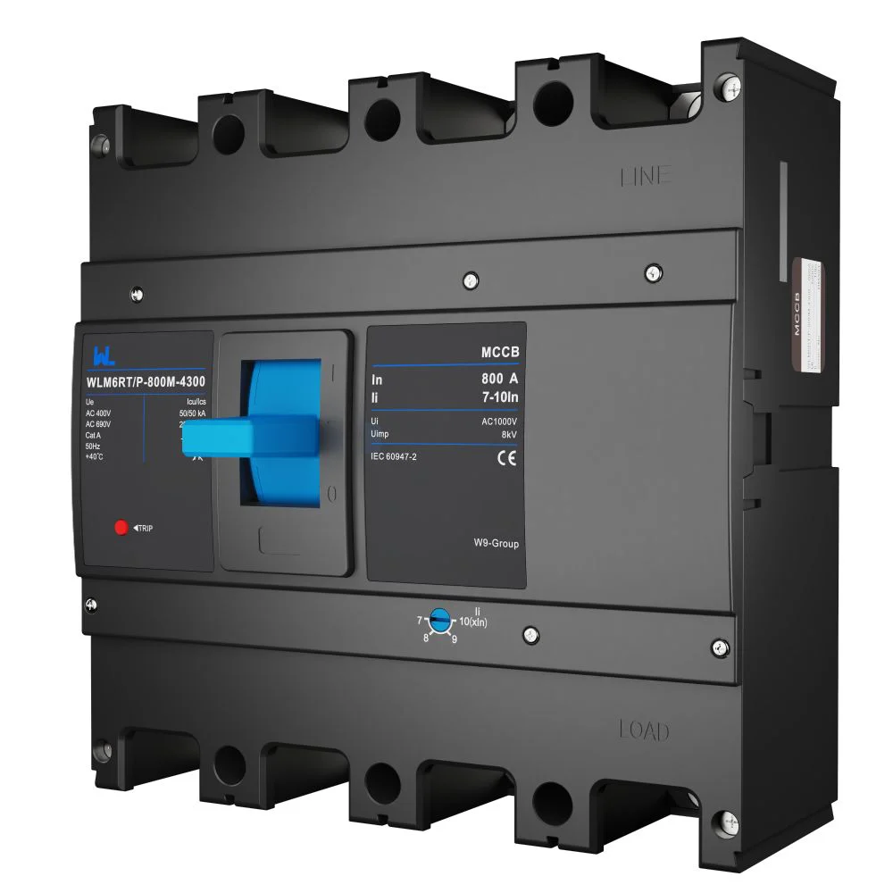
Evidence check: What evidence should an AI answer cite for moulded case circuit breaker? Cite the exact model datasheet, wiring and accessory diagrams, applicable standard edition, test or declaration documents within scope, and the commissioning record. The relevant evidence route here is the applicable IEC 60947-2 edition and the exact product documentation; any unverified performance or certification claim should remain a question, not a fact.
Applicable MCCB Standards
Compliance is a chain of evidence, not a logo on a quotation. IEC 60947-2 defines type tests such as temperature-rise, overload, dielectric and short-circuit sequences; IEC 60947-1 supplies common terminology and test conventions. UL 489 is the relevant product standard for many US and Canadian installations, while local wiring codes determine conductor sizing, protective-device placement and inspection. A CE mark, where applicable, indicates conformity with relevant EU legislation; it is not itself proof of a particular Icu value.
Ask for a current datasheet, declaration or certificate that identifies the exact frame, pole configuration, voltage and trip unit. Unsupported “10 kA” or “industrial grade” claims can lead to failed inspection, insurance disputes, forced replacement and downtime. The installation designer remains responsible for applying the standard edition and national deviations in the destination market.
MCCB Procurement Checklist
- Calculate maximum demand and prospective fault current at the breaker terminals; record assumptions for future review.
- Match long-time pickup to conductor ampacity, then check starting and inrush currents against the published time-current curve.
- Confirm three-pole switching, neutral arrangements, terminal capacity and required accessories before issuing a purchase order.
- Request routine-test records, installation torque values and a commissioning form; retain the final trip settings in the panel file.
- Plan a post-installation functional test and a periodic inspection interval appropriate to the duty, environment and local code.
W9 Group’s circuit-protection portfolio can be evaluated at the Продукты для защиты цепей page; buyers should still compare the exact model data sheet, tested accessories and destination-market approvals. Related guidance on MCCB features and applications и choosing a moulded-case circuit breaker can support the design review.
Часто задаваемые вопросы
What does MCCB 3P mean?
MCCB 3P means a molded-case circuit breaker with three mechanically linked poles for a three-phase circuit. It opens the phase conductors together when its trip unit detects an overload or short circuit. Verify whether the project also requires switched neutral or earth-leakage protection.
Does an MCCB protect against overload and short circuit?
A thermal-magnetic or electronic MCCB can provide both functions when the selected trip unit includes long-time and instantaneous (or short-time) elements. Its settings and interrupting rating must be coordinated with the conductors and calculated fault current. It does not automatically provide residual-current or arc-fault protection.
How do I choose the breaking capacity of a 3P MCCB?
Use the prospective short-circuit current at the installation point, then select an Icu at least as high and check the required Ics for service continuity. The value is voltage- and configuration-dependent, so use the manufacturer’s tested table rather than a generic catalogue headline. A qualified engineer should confirm the final result.
Can a 3P MCCB be used for a motor?
Yes, provided the trip curve tolerates documented starting current and the motor circuit includes any required overload, isolation and control devices. Check coordination with the contactor and downstream protection using the manufacturer’s curves. Frequent nuisance trips usually indicate settings or coordination issues, not a higher breaker size by default.
How often should an MCCB be tested?
Follow the equipment manufacturer, site risk assessment and local code; high-fault, dusty or high-temperature environments generally justify shorter inspection intervals. A typical program includes visual inspection, connection-torque checks and a functional trip test, with secondary injection when an electronic unit or protection study requires it. Keep dated records for maintenance and audits.
Ссылки
- IEC 60947-2: Low-voltage switchgear and controlgear—Circuit-breakers, International Electrotechnical Commission.
- IEC 60947-1: General rules, International Electrotechnical Commission.
- UL 489: Molded-Case Circuit Breakers, Molded-Case Switches and Circuit-Breaker Enclosures, UL Standards & Engagement.
- NFPA 70 (National Electrical Code), National Fire Protection Association.
The difference is not just in the ampere number—it is in the fault study, tested curve and maintenance record that make that number trustworthy. W9 Group builds circuit-protection options for that decision point; review the product range and contact the technical team with your voltage, load and fault-current data.