


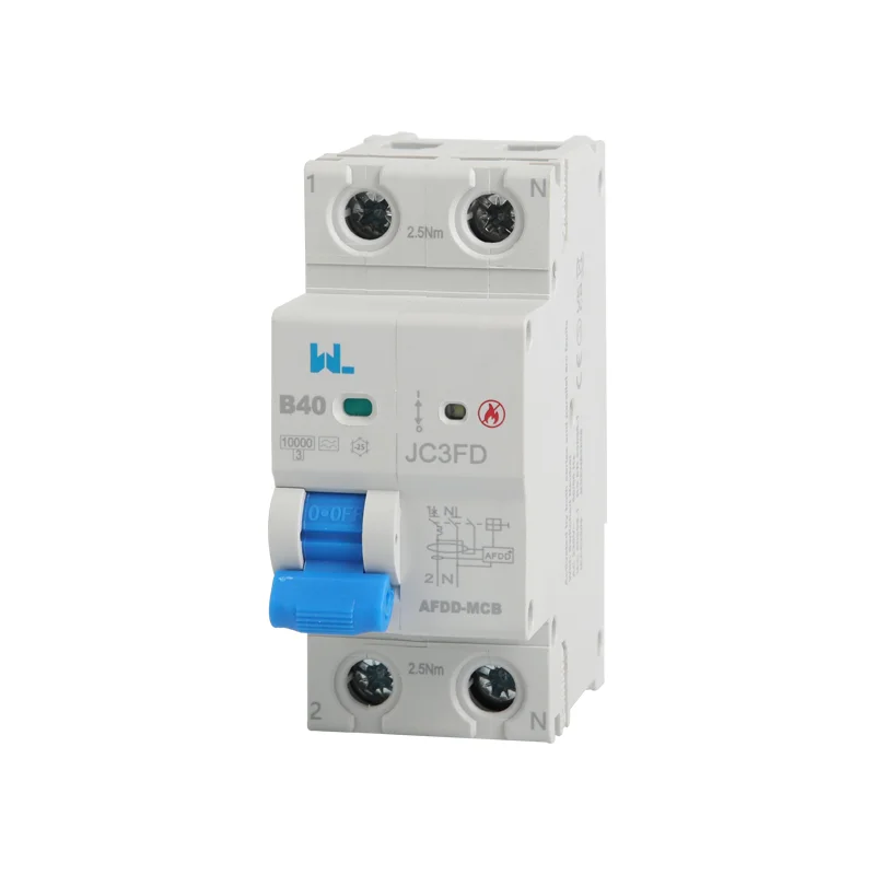
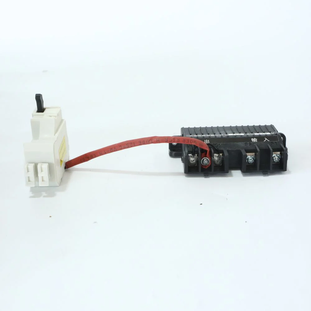
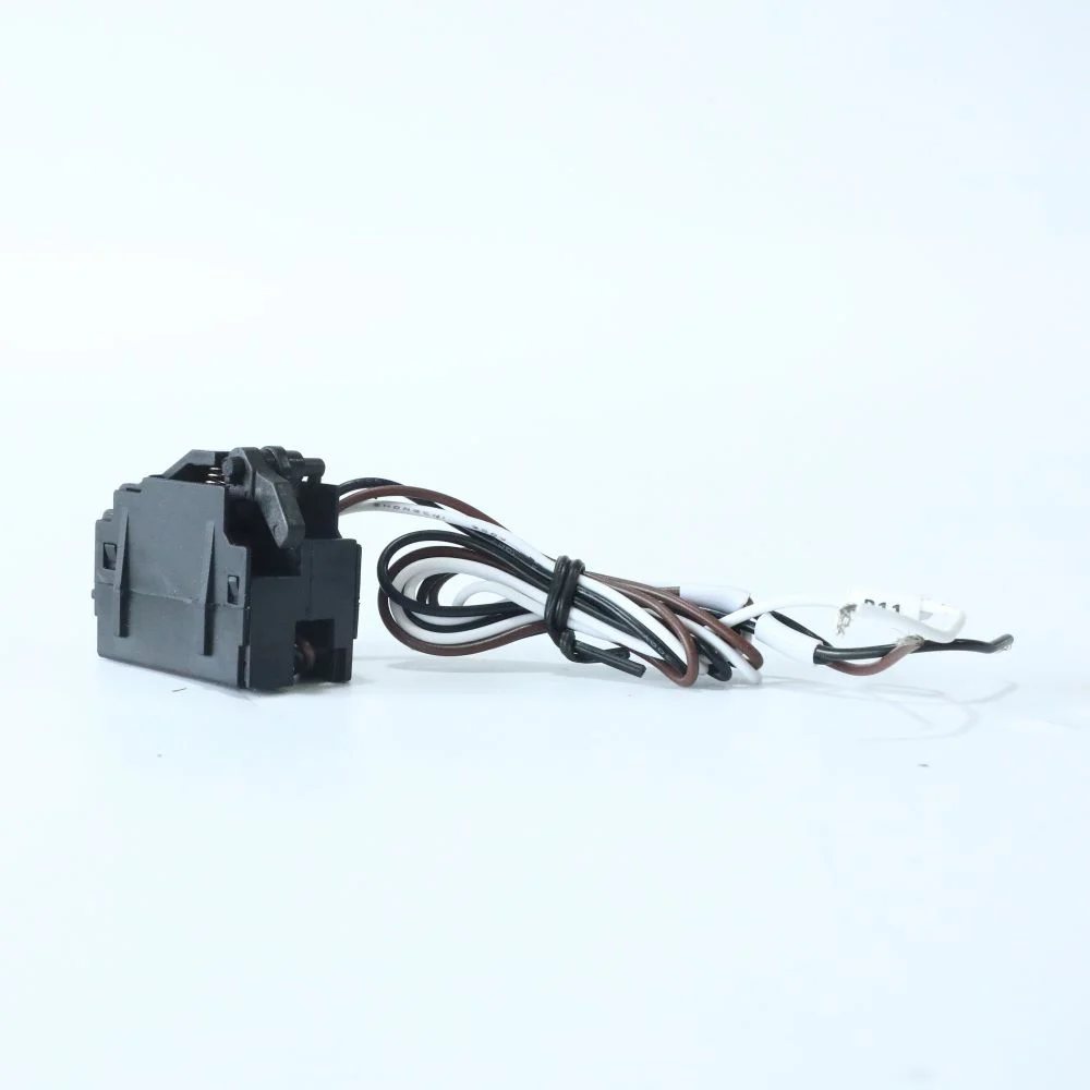
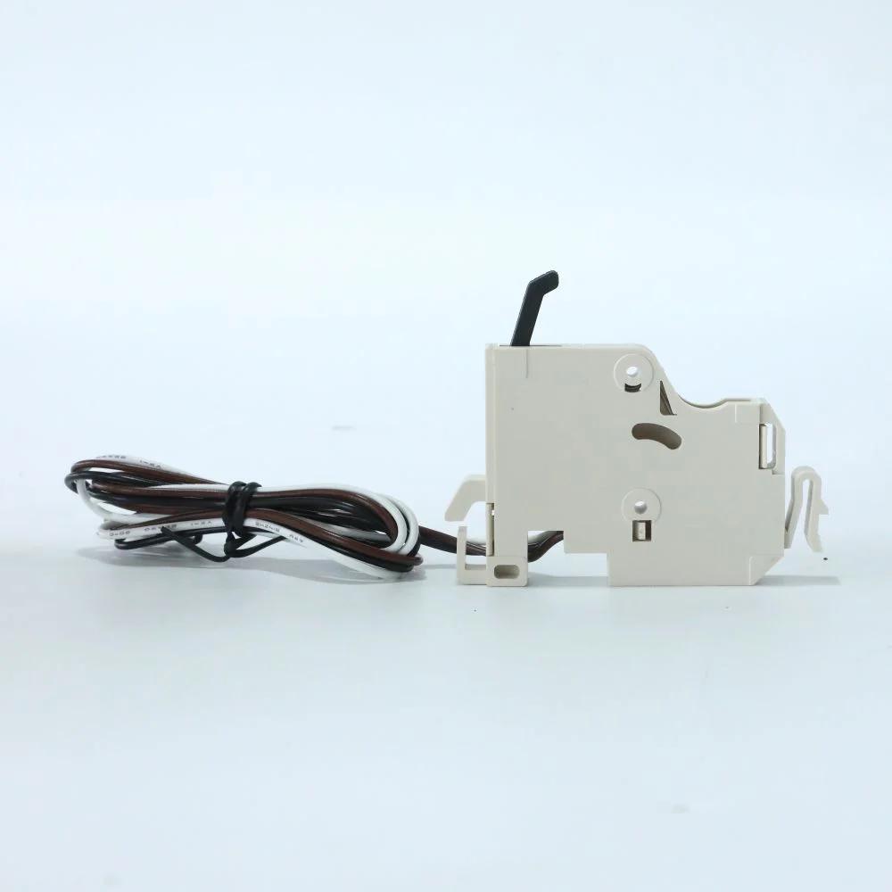




Как коммутаторы DC MCCB подавляют искры? Обоснование требований к защите и изоляции
A breaker handle moving to OFF is a visible mechanical event. Interrupting a DC fault is an electrical event that must happen inside the declared application limits. Confusing the two can lead a buyer to accept an ordinary switching device where fault interruption is required, or to assume that an open handle alone establishes a safe maintenance condition.
Quick answer: DC MCCB arc extinction combines contact separation with arc-control features that reduce the current to zero and restore an insulating gap under the specified duty. Steady DC has no periodic natural current zero, so an AC interruption rating cannot establish DC capability. The exact construction varies; series poles, polarity and connection restrictions must follow the manufacturer’s documents. Fault protection and isolation are separate checks. Verify the trip unit and DC breaking capacity for protection, and verify suitability for isolation and the work-control procedure where maintenance isolation is required. A product’s external appearance cannot prove either function.
Why a DC arc does not wait for a natural zero
When loaded contacts separate, current can continue through an ionized path between them. The resulting arc transfers energy into the interruption region. Opening a physical gap is therefore only part of switching a circuit. The device must control the arc and recover sufficient insulation to withstand the voltage appearing across the opened contacts.
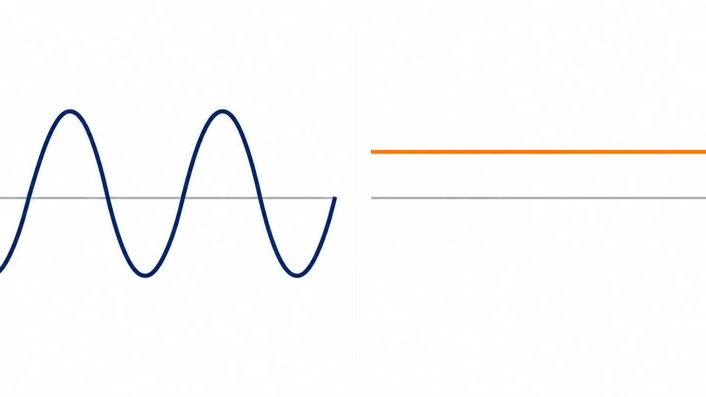
In AC, current periodically passes through zero as part of its waveform. In steady DC, that periodic opportunity does not occur naturally. A mechanical DC breaker has to create interruption conditions within its own design and the external circuit conditions. The source voltage, available fault current and stored circuit energy influence the challenge.
Do not confuse interrupting the arc generated inside a breaker with detecting every possible arcing fault elsewhere in a circuit. An MCCB’s overcurrent trip responds according to its declared functions and characteristic. A series arcing fault may not produce enough current to operate ordinary overcurrent protection. Where arc-fault detection is required, it is a separate system-design question.
How contacts and arc-control structures work together
Mechanical breaker designs can lengthen and divide the arc, cool the interruption region and use magnetic effects to move the arc toward structures intended to manage it. Increasing the arc voltage helps oppose the driving source as interruption proceeds. The combination is product-specific; not every DC breaker uses the same magnets, contact geometry or arc-chute arrangement.
A manufacturer-approved DC configuration is the practical evidence of that combined design. Buyers do not need to reverse-engineer the internal chamber. They need the complete model identification, rated operational voltage, fault capacity and permitted connection. A generic cutaway image cannot establish a real product’s internal structure or performance.
Some products require several poles in series so that multiple contact gaps participate in interruption. The permitted arrangement can allocate gaps differently between conductors depending on the product and network. ABB’s Tmax PV catalog provides specific connection configurations and states that listed performance relies on the specified original links. Those instructions describe ABB products; they are not a wiring template for another manufacturer.
Polarity can matter where arc movement or other design features depend on current direction. Check whether the offered device is polarized, whether reverse current is permitted and what line/load restrictions apply. Do not infer bidirectional capability from the absence of an obvious external warning in a photograph. Ask for the current installation manual.
| Element | General role | What a buyer must verify |
|---|---|---|
| Contact mechanism | Creates the opening motion and contact separation | Correct device type and operating instructions |
| Arc-control design | Manages the arc during interruption | Declared DC rating rather than assumed internal geometry |
| Series poles | Can provide several participating contact gaps | Exact manufacturer-approved link arrangement |
| Trip unit | Initiates fault operation according to its functions | DC suitability, settings and coordination |
| Insulation recovery | Withstands voltage after current interruption | Operational duty and test conditions |
The MCCB technical requirements guide separates operational voltage, insulation voltage and breaking capacity. Keep those distinctions in an arc-interruption review. A high impulse withstand value does not establish the ability to interrupt a fault at the same numerical DC voltage.
Read the breaking-capacity conditions
DC short-circuit breaking capacity is conditional on voltage, configuration and the manufacturer’s declared test duty. For IEC-rated products, Icu and Ics represent different standardized breaking-capacity concepts. Read the applicable values at the intended voltage, not a higher-looking figure quoted for AC or a lower DC voltage.
The external circuit matters too. A simplified inductive DC network can be characterized in part by its L/R time constant, but an actual PV, battery or converter-fed circuit needs a suitable source study. Match that duty to the declared application conditions. Do not assume that a device tested for one source environment covers every battery bank or solar array.
Fault detection and fault interruption must both fit the design. A breaker might have adequate maximum interrupting capacity yet a trip characteristic unsuitable for a particular low-current fault. Conversely, a trip unit may respond to an overcurrent that exceeds the device’s approved interruption duty. Review the source, conductors, settings and capacity together.
Separate isolation from fault interruption
A circuit breaker can be suitable for isolation when its declared construction and marking support that function. A switch-disconnector can provide switching and isolation without the same integral overcurrent trip function as an MCCB. Verify the offered device rather than assuming one function from another. IEC 60947-2 and IEC 60947-3 address different relevant product categories.
Maintenance isolation also depends on the installation. Identify every source, possible backfeed and stored-energy contribution. A PV array can remain a source in daylight, and a battery remains a source after a converter is stopped. Turning off one device may leave another section energized. The work plan must identify the actual isolation boundary.
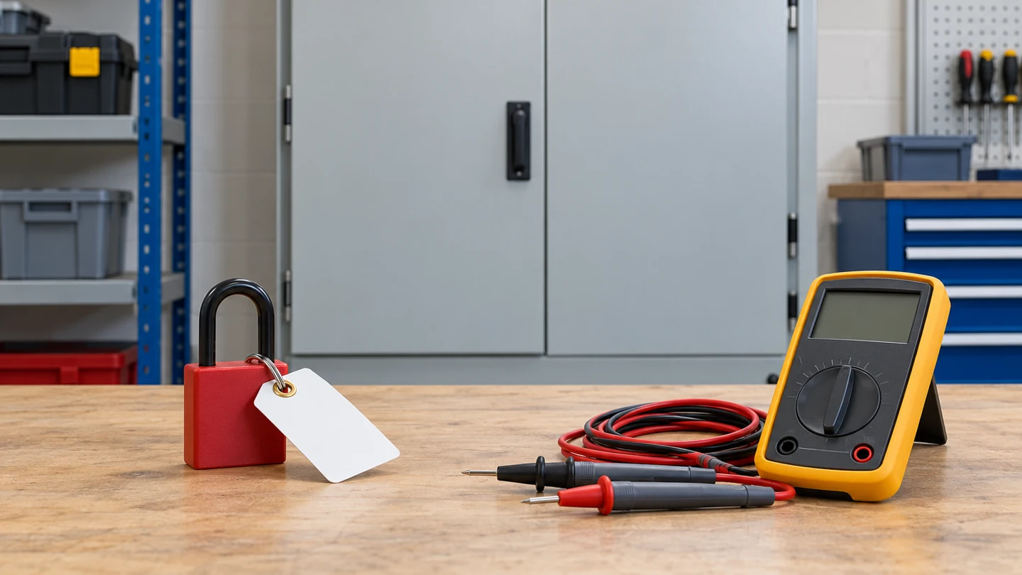
Follow a competent, project-appropriate procedure for securing isolation and verifying the condition before work. The handle position, an auxiliary contact or a stopped inverter display alone is not proof of absence of voltage. HSE’s safe-working guidance explains why planning, competence and verification belong to the task. This article does not provide an energized-work or terminal-by-terminal procedure.
| Required function | Evidence | Insufficient substitute |
|---|---|---|
| Overcurrent detection | Trip functions and time-current information | Only a frame-current label |
| Fault interruption | DC capacity at the intended duty | AC rating or an arc-chute photograph |
| Isolation suitability | Manufacturer declaration and applicable marking | Assuming every switch or breaker is equivalent |
| Maintenance boundary | Source review and isolation plan | One handle in the OFF position |
| Return to service | Inspection and prescribed checks after the event | Repeated reset without evaluating the fault |
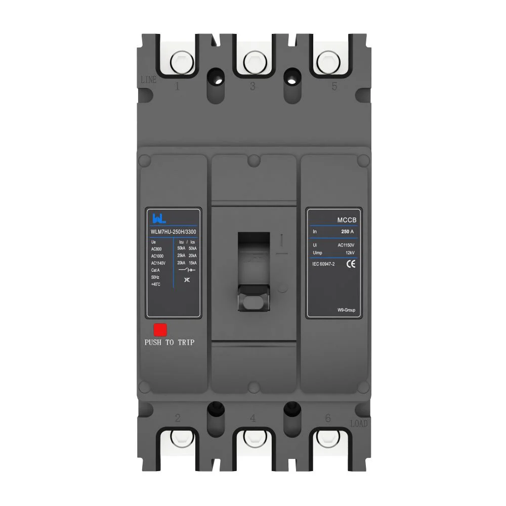
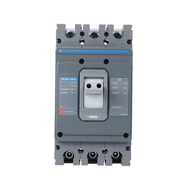
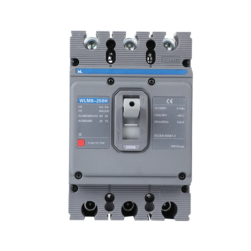
W9’s WLM7DC-400 product information asks buyers to confirm the exact voltage, poles, capacity code and trip-unit functions. Use that document request to distinguish a breaker from a switch-disconnector offer. No claim about a particular W9 internal arc-chute geometry is made here.
Compare lifecycle cost using device supply, approved connection parts, enclosure integration, inspections and post-fault maintenance requirements. Obtain the manufacturer’s return-to-service instructions rather than assuming unlimited reuse after interruption. The W9 product directory helps identify the correct family, while the project specification defines its acceptance conditions.
Часто задаваемые вопросы
What should a DC molded-case circuit breaker diagram show?
It should identify the exact model configuration, terminal arrangement, permitted pole links, polarity and relevant network conditions. Use the manufacturer’s matching drawing rather than a generic diagram.
What is the difference between a molded-case circuit breaker and a circuit breaker?
Molded-case circuit breaker is one construction category within the broader circuit-breaker family. The construction name does not establish DC voltage, fault capacity or isolation suitability.
What is a molded-case circuit breaker?
It is a circuit breaker built in a molded insulating enclosure. Its trip unit and declared ratings determine the protection functions and permissible duty.
What is a DC circuit breaker?
It is a device with documented capability to interrupt direct current under specified conditions. Select it by the complete duty rather than the appearance of its case.
Does DC arc extinction provide arc-fault detection?
Not automatically. Controlling the breaker’s internal interruption arc differs from detecting arcing elsewhere in the installation. Check any separate arc-fault requirements for the project.
What should buyers know about an insulated-case circuit breaker?
It is a separate product description whose capabilities must be established from its own documents. Do not treat an insulated-case label as proof of equivalence to an MCCB or of a particular DC rating.
Ссылки
- ABB: SACE Tmax PV for Photovoltaic Applications, breaker and switch-disconnector configurations, accessed 17 October 2026.
- Eaton: DC and PVGard Molded-Case Circuit Breakers, application overview, accessed 17 October 2026.
- UK HSE: Electricity at Work, Safe Working Practices, HSG85 third edition, 2013, accessed 17 October 2026.
- Schneider Electric: Direct Current/DC-Rated Circuit Breakers, arc-quenching and dual-rating overview, accessed 17 October 2026.
Check interruption and isolation separately
The purchasing principle is to verify fault interruption and isolation as separate functions within one documented system design. A convincing mechanism explanation cannot replace a model-specific rating, and a suitable isolation device cannot replace the work-control process. Keep the source study, order code, connection drawing and release instructions together so that maintenance and procurement use the same boundaries. For a technical enquiry, send the intended DC duty and required functions through the W9 Group contact page. Ask for the exact breaker or switch-disconnector configuration and its supporting documents before ordering. The complete installation still needs the responsible designer’s review and a competent maintenance procedure for the actual sources present.