































Shunt Release for MCCB: JCMX1-125 Remote Trip Solution
Shunt Release for MCCB: JCMX1-125 Remote Trip Solution
When Maya, a facilities engineer in Rotterdam, pressed the emergency-stop circuit during a panel commissioning test, the downstream equipment stayed energized. She had wired a remote-trip accessory, heard its coil click, and still saw the feeder breaker closed. The visible failure looked like a bad breaker. The reversal came during the drawing review: the selected JCMX1-125 is a shunt-trip accessory for compatible MCBs and RCBOs, not a universal MCCB release, and it provides no auxiliary feedback contact. The problem was selection and verification, not a failed product.
Summary: A shunt release opens a breaker when its coil receives the specified control voltage; it does not replace the breaker’s overload or short-circuit protection. The public JCMX1-125 listing describes an MX shunt trip that remotely opens an MCB/RCBO when voltage is applied, mounts on the device’s left side, and has no auxiliary feedback. For an MCCB project, confirm frame-family compatibility, coil voltage, pin geometry, and the control-circuit test sequence against the breaker maker’s documentation and IEC 60947-2 requirements before ordering.
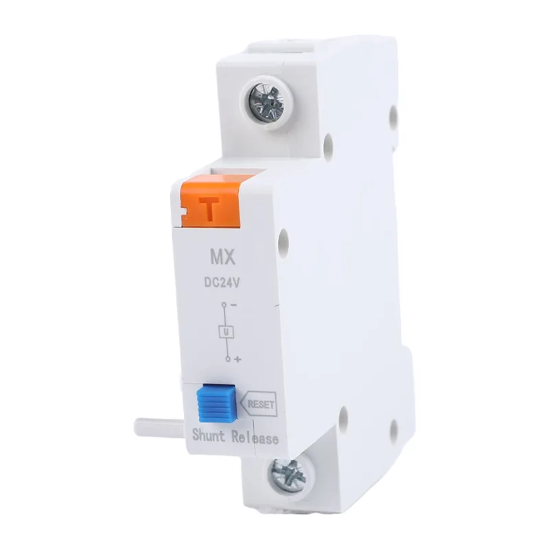
What a shunt release actually does
A shunt release (also called a shunt trip) is an electrically actuated mechanism linked to a circuit breaker’s opening path. A remote signal—such as an emergency-stop relay, fire alarm interface, or process interlock—energizes the coil. The mechanism unlatches the breaker so its contacts open. The breaker then interrupts current using its own contact system and arc-control design.
The release initiates an opening command; it is not a current sensor and cannot detect overloads. Thermal-magnetic or electronic trip functions remain responsible for fault protection, so list the shunt signal separately from protective trips and “breaker open” indication.
The JCMX1-125 product page uses the term “MX” and states “only Shunt Trip Release Function, no Auxiliary Feedback.” Treat that sentence as a functional boundary. If a PLC or fire panel must prove that the breaker opened, specify a separate auxiliary contact or a breaker model with an integrated status output.
Where the JCMX1-125 fits—and where it does not
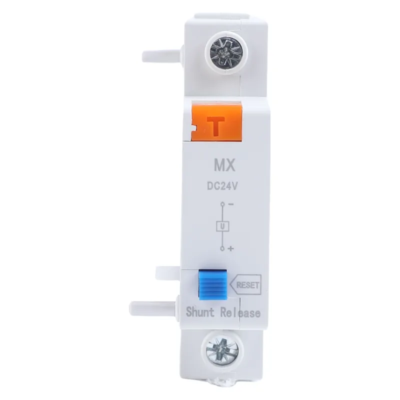
The published product name is “MCB Accessories JCMX1-125 Shunt trip release MX.” Its description says the device remotely opens an MCB/RCBO when voltage is applied and installs on the left side with a special pin arrangement. Those are the verified facts available for this model. The page does not publish a coil-voltage range, power draw, trip time, pole count, breaking capacity, environmental rating, or certification list.
That missing data matters when a buyer searches for a “shunt release for MCCB.” MCCBs use different accessory chambers, latches and terminals from many MCB families. A similar-looking module may not engage the latch or may require a different coil voltage. Do not infer compatibility from the JCMX1-125 code or photograph; ask for the exact breaker series, frame, accessory position, control voltage and wiring diagram.
Engineering the remote-trip circuit
Start with the control-voltage evidence
Never energize an accessory from a convenient supply until its nameplate or datasheet confirms the rated voltage and AC/DC type. A control circuit should include the overcurrent protection, isolation method, and terminal identification required by the panel design. If the public listing does not state the coil rating, record it as an open technical query rather than guessing.
Separate command, indication, and reset
Use one set of contacts to issue the trip command and a separate, verified device to report status. A shunt release generally opens the breaker; it does not automatically close it. Define whether operators reset locally, whether a remote close is permitted, and how a latched emergency stop is cleared. This prevents a “trip successful” assumption based only on a relay LED.
Test the complete chain
During FAT or commissioning, measure the control voltage at the accessory terminals, operate the initiating device, and verify mechanical opening at the breaker. Repeat at the minimum and maximum supply conditions specified by the approved datasheet. Test continuity and insulation only with the accessory isolated as instructed by the breaker manufacturer; an insulation tester applied across an electronic or coil circuit can damage it.
JCMX1-125 compared with other remote-opening approaches
The right solution depends on the host breaker and the required evidence. The table below is a procurement aid, not a performance ranking; values such as price and delivery vary by frame and region.
| Approach | Opening command | Status feedback | Compatibility check | Total-cost considerations |
|---|---|---|---|---|
| JCMX1-125 MX accessory | Voltage applied to shunt coil | None stated; product page says no auxiliary feedback | Left-side MCB/RCBO pin interface; confirm exact family | Low accessory count, but separate status contact may be needed |
| MCCB manufacturer shunt trip | Coil command defined by MCCB maker | Often optional auxiliary or alarm contacts | Matched to frame, trip unit and accessory cavity | Higher part cost can reduce retrofit and wiring risk |
| Undervoltage release | Breaker opens when control voltage is removed or falls | Depends on auxiliary package | Requires a compatible UVR module and maintained supply | Useful for fail-safe schemes; supply supervision adds cost |
| Motor operator plus trip accessory | Motor handles close/open; shunt or UVR trips | Usually paired with auxiliary contacts | Requires space, interlocks and duty-cycle review | Best for automation, with higher panel footprint and maintenance |
Selection matrix for an MCCB project
| Project question | Evidence to collect | Decision gate |
|---|---|---|
| What must open? | One-line diagram, fault level, breaker series and frame | Accessory is listed for that exact breaker family |
| What initiates the trip? | Emergency stop, fire alarm, PLC or process relay logic | Contact arrangement, reset philosophy and fail-state are documented |
| What voltage is available? | Measured nominal voltage, tolerance and AC/DC source | Coil rating and inrush data are confirmed by the manufacturer |
| How is success proven? | Auxiliary contact, alarm contact or monitored input | Feedback is independent of the command relay indication |
| What records are required? | Wiring diagram, test sheet, labels and maintenance interval | As-built package identifies the accessory and test method |
Standards, testing, and compliance boundaries
IEC 60947-2 covers circuit breakers for low-voltage switchgear and controlgear, including operating characteristics and verification tests for the breaker assembly. Use it to frame the host MCCB/MCB requirements; it is not evidence that the JCMX1-125 itself is certified. IEC 60947-1 provides general rules for low-voltage switchgear, while IEC 60947-5-1 addresses control-circuit devices and switching elements that may appear in the initiating circuit. The applicable edition and national adoption must be checked for the destination market.
In North America, UL 489 is commonly used for molded-case circuit breakers, and NFPA 70 (the National Electrical Code) governs installation practices. Neither reference allows a seller to imply a listing without a traceable certificate for the exact product and configuration. A specification that says “IEC compliant” without test reports, rated values, and a responsible manufacturer can create inspection delays, redesign cost, and warranty disputes.
For a project using the JCMX1-125, retain the product page, the host-breaker accessory schedule, control-voltage confirmation, and witnessed trip-test record. Mark any unverified parameter—especially coil voltage, endurance, temperature range, and certification—as “to be confirmed.” This is more defensible than filling gaps with typical values from another MX accessory.
Practical buying and installation checklist
- Match the host first. Send the breaker manufacturer, series, pole count, frame and mounting side with the inquiry. For alternatives, review the site’s circuit protection products category.
- Confirm the coil. Obtain rated control voltage, AC/DC designation, terminal diagram and allowable duty. Do not energize an unknown coil.
- Specify feedback separately. Because the JCMX1-125 listing states no auxiliary feedback, add a compatible auxiliary contact when the control system needs proof of opening. The guide to auxiliary contacts for MCCBs explains the distinction.
- Witness the trip path. Test from the real initiating device through the relay, accessory and breaker mechanism, then document reset and re-energization steps.
- Keep the evidence pack. Store drawings, photographs, serial or batch references, and the approved installation sheet with the panel records. For MCCB selection context, see the site’s MCCB features and applications guide.
When sourcing through J&Co (the brand shown on the test site), treat the JCMX1-125 as a configurable accessory request: provide the exact host device and control requirements so the supplier can return matching documentation. The public listing supports remote opening of compatible MCB/RCBO devices; it does not by itself approve an MCCB retrofit.
Frequently asked questions
Can the JCMX1-125 be installed on any MCCB?
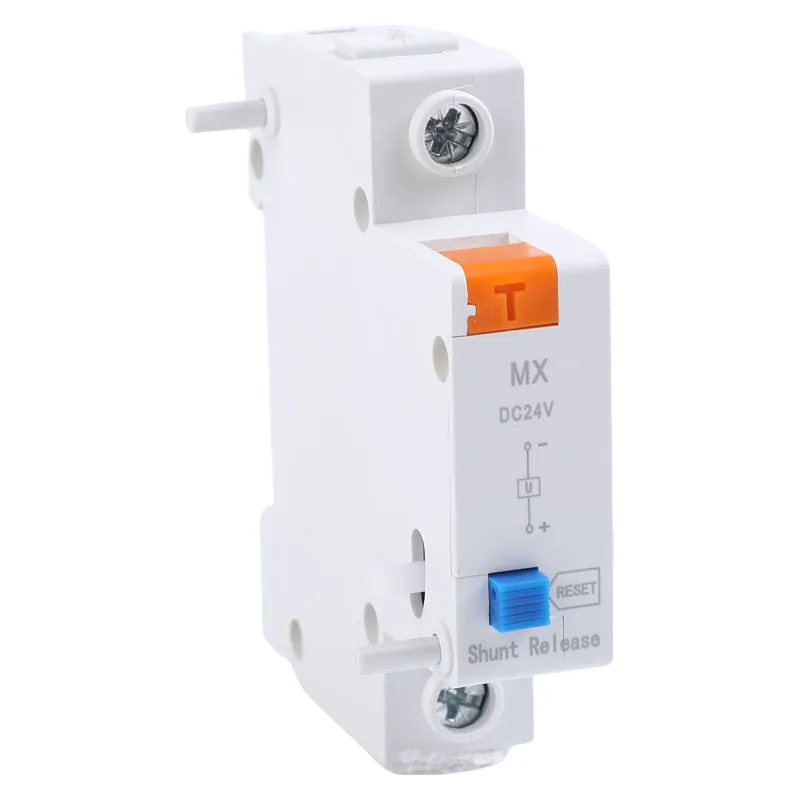
No. The verified listing identifies it as an MCB/RCBO accessory with a special left-side pin arrangement. An MCCB installation requires written confirmation that the exact frame and accessory cavity accept it.
What happens when voltage is applied to a shunt release?
The energized coil commands the breaker mechanism to open. The breaker’s own contacts and arc-control system interrupt the load; the shunt release does not provide overload protection.
Does JCMX1-125 provide breaker-open feedback?
The product excerpt explicitly says “no Auxiliary Feedback.” Add a compatible auxiliary or alarm contact when a PLC, fire panel or BMS must verify the open state.
Which coil voltage should I order?
The public page does not state a coil-voltage range. Confirm the rated AC/DC voltage and tolerance from the current datasheet or quotation against the control supply measured on site.
Is a shunt trip the same as an undervoltage release?
No. A shunt trip opens when its coil is energized, while an undervoltage release typically opens when its sustaining voltage is removed or drops below its operating threshold. Select according to the project’s fail-safe philosophy and applicable code.
References
- IEC 60947-2, Low-voltage switchgear and controlgear—Circuit-breakers (International Electrotechnical Commission).
- IEC 60947-1, General rules (International Electrotechnical Commission).
- UL 489, Molded-Case Circuit Breakers (UL Solutions).
- NFPA 70, National Electrical Code (National Fire Protection Association).
Closing principle: A remote trip is only as dependable as the match between coil, mechanism, wiring and proof of operation.
Ready to verify a JCMX1-125 application or identify a true MCCB-compatible shunt release? Review the JCMX1-125 product page, then contact the J&Co team with your breaker model, frame, control voltage and feedback requirement for a documented recommendation.