





























1P+N MCB: A Compact Circuit Breaker for Modern Electrical Safety
1P+N MCB: A Compact Circuit Breaker for Modern Electrical Safety
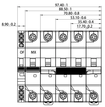
When a facilities engineer in Manchester replaced a tripping single-phase breaker after a tenant complained about a dark office, the new device fit the rail perfectly but left the neutral permanently connected. A fault-finding test still showed voltage on the isolated load, forcing a late-night rewire. The breaker was not defective; the specification confused a one-pole device with a switched-neutral arrangement. That is why a project team asking “what is a 1P+N MCB?” must answer the pole, neutral and isolation questions together.
Summary: A 1P+N MCB protects the line conductor against overload and short circuit while providing a neutral pole for switching or isolation, depending on its design. In a 230 V single-phase board, verify rated current, B/C/D curve, breaking capacity and neutral-pole behavior against IEC 60898-1 (or IEC 60947-2 for the applicable industrial duty). Check cable ampacity, prospective fault current and local wiring rules before ordering; then prove polarity and isolation during commissioning.
A 1P+N MCB occupies two module positions in many DIN-rail assemblies: one pole carries the thermal-magnetic release, while the second pole is a neutral contact that may be switched simultaneously. Some products protect both poles; others protect only the phase and use a linked neutral contact. The marking and wiring diagram, not the shorthand “2P,” determine the actual function. This distinction matters for maintenance, residual-current coordination and safe disconnection.
How a 1P+N arrangement differs from a 1P or 2P breaker
A single-pole MCB interrupts the line only. It can protect a branch circuit, yet the neutral remains connected when the handle is off unless a separate isolator is provided. A true two-pole MCB has overcurrent releases in both poles. A 1P+N model normally combines one protected line pole with a switched neutral, preserving compactness while allowing both conductors to be isolated for service. The exact neutral switching sequence and whether the neutral is protected must be confirmed in the data sheet.
| Configuration | Typical function | Neutral behavior | Procurement check |
|---|---|---|---|
| 1P | Overload and short-circuit protection on one line | Usually not switched | Provide a separate neutral bar or isolator where required |
| 1P+N | Line protection with linked two-conductor disconnection | Switched; protection depends on model | Read pole diagram, terminal markings and test scope |
| 2P | Overcurrent protection on two poles | Neutral may be protected or treated as a second phase | Confirm suitability for the supply system and neutral conductor |
| RCBO 1P+N | Overcurrent plus residual-current protection | Line and neutral pass through the sensing path | Use IEC 61009-1 data and test the RCD function separately |
For a broader device-family comparison, the site’s circuit breaker guide explains where MCBs, RCCBs and RCBOs differ. A 1P+N MCB does not detect earth leakage by itself; add an RCCB or select an RCBO when the design requires residual-current protection.
Ratings that make the compact format safe
Start with the design current, not the available space. For an illustrative 230 V, 2.3 kW heater, I = P/V = 2,300/230 = 10 A. A 10 A device could be considered only after checking conductor ampacity, ambient temperature, installation method, grouping and duty cycle. IEC 60364-4-43 principles require the protective device to coordinate with the cable; a breaker that is physically convenient but electrically oversized can allow damaging conductor heating.
The trip curve also changes how the same rated current behaves during inrush. Under common IEC 60898-1 explanatory bands, B curves respond magnetically around 3–5 × In, C around 5–10 × In and D around 10–20 × In. These are test ranges, not a promise of one fixed trip value. For LED drivers or office sockets, B or C may be suitable; a small motor may need C, while D should be justified by measured starting current and minimum fault current. The detailed B, C and D curve explanation shows how to read the time-current envelope.

Breaking capacity is separate from the curve. If the measured prospective short-circuit current at the board is 4 kA, the marked Icn (or the applicable industrial Icu/Ics values) must cover that duty with any specified backup fuse. On long feeders, calculate the minimum fault current as well as the maximum: a high-threshold D curve may fail to trip magnetically when impedance is high. Keep the calculation, manufacturer time-current curve and coordination table in the project file.
Where 1P+N MCBs create value
The compact arrangement is useful in single-phase homes, offices, retail fit-outs and small control panels where simultaneous line-neutral isolation improves service safety without the width of a full two-pole protected breaker. It can also simplify retrofit schedules when the existing board has limited module capacity. The benefit is operational, not a license to ignore wiring rules: a neutral that is undersized, shared incorrectly or interrupted out of sequence remains a hazard.
| Application | Why 1P+N helps | Evidence to request | Common pitfall |
|---|---|---|---|
| Residential final circuit | Line protection with clear isolation for maintenance | Rated current, curve, Icn and neutral switching diagram | Assuming a 1P+N label means residual-current protection |
| Office socket or lighting board | Two-conductor disconnection in a narrow modular layout | Inrush assessment, cable calculation and torque values | Selecting a D curve to cure nuisance trips without fault-current review |
| Small HVAC or pump feeder | Compact feeder protection where starting current is known | Motor starting data, TCC and selectivity table | Ignoring restart inrush or upstream RCCB compatibility |
| Control or OEM panel | Consistent pole arrangement across exported builds | Declaration, test report and destination-market standard | Transferring a certificate from another frame or rating |
For residual-current protection in the same footprint, an RCBO may be the better choice. The site’s RCBO function article explains why overload and leakage duties should be coordinated rather than assumed to be interchangeable.
Standards, installation and commissioning
IEC 60898-1 covers circuit-breakers for overcurrent protection in household and similar AC installations, including construction, ratings and verification tests. IEC 60947-2 addresses low-voltage circuit-breakers in switchgear and controlgear, often with industrial utilization categories and different test assumptions. IEC 60364-4-43 is an installation-design reference for overcurrent coordination; it is not a product certification. Where an RCBO is specified, IEC 61009-1 addresses residual-current circuit-breakers with integral overcurrent protection.
Destination-market rules still apply. In North America, UL 489 covers branch and feeder circuit breakers, while UL 1077 covers supplementary protectors inside equipment; one listing cannot be casually substituted for the other. A CE mark, UL listing or other declaration must match the exact model, pole arrangement, voltage and interrupting rating. Unsupported certification language can delay a submittal, trigger redesign or create warranty exposure.
During installation, follow the maker’s line/load and torque instructions, keep neutral conductors on the correct bar, and label the circuit schedule. A competent person should verify continuity, polarity, insulation resistance and prospective fault current; an RCD/RCBO test is separate from an MCB functional check. After a fault, inspect terminals for heat discoloration and replace a breaker that has exceeded its tested duty. Never rely on handle position alone to prove dead equipment—use an approved isolation and test procedure.

Selection checklist for buyers and panel builders
- Record supply voltage, frequency, earthing system, phase, neutral arrangement and number of poles.
- Calculate design current and cable ampacity with ambient and grouping derating; do not size from module width.
- Compare measured inrush with the exact B/C/D time-current curve and verify disconnection at minimum fault current.
- Confirm Icn or Icu/Ics, terminal capacity, busbar compatibility, polarity and the neutral switching sequence.
- Request the declaration, test reports, wiring diagram, installation torque and destination-market instructions; retain them with commissioning records.
W9 Group (Zhejiang W9 Group Technology Co., Ltd.) supplies low-voltage protection products and documentation support for OEM/ODM panel projects. Treat that capability as a sourcing input, not a substitute for the engineer’s design approval; the exact 1P+N MCB model still needs its ratings and test scope matched to the installation. Explore the circuit protection products range when preparing a compliant bill of materials.
Frequently asked questions
What does 1P+N mean on a circuit breaker?
It identifies one line pole plus a neutral pole in a single modular device. The line usually carries the thermal-magnetic release, while the neutral is switched or linked; the manufacturer’s diagram confirms whether the neutral is protected.
Is a 1P+N MCB safer than a 1P MCB?
It can provide more complete isolation because line and neutral open together, which helps maintenance on a single-phase circuit. It is not automatically safer if the neutral sequence, ratings or wiring are wrong, and it does not provide earth-leakage protection.
Can a 1P+N MCB protect against electric shock?
An MCB responds to overload and short-circuit current, not ordinary leakage through a person. Use an RCCB or RCBO with the correct sensitivity and installation rules when residual-current protection is required.
What rating should I choose for a 1P+N breaker?
Select rated current and curve from the calculated load, conductor ampacity, inrush and fault current. Then confirm the marked breaking capacity, voltage and pole arrangement against the applicable standard; a 10 A example cannot be copied to every 230 V circuit.
Does a 1P+N MCB switch the neutral?
Most 1P+N devices are designed to switch the neutral with the line, but the timing and whether the neutral has overcurrent protection vary. Check terminal labels and the manufacturer’s wiring instructions before installation or replacement.
References
- IEC 60898-1, Circuit-breakers for overcurrent protection for household and similar installations.
- IEC 60947-2, Low-voltage switchgear and controlgear—Circuit-breakers.
- IEC 61009-1, Residual current operated circuit-breakers with integral overcurrent protection.
- NFPA 70, National Electrical Code.
The compact breaker earns its place when every pole has a documented purpose: protect the conductor, isolate the circuit and coordinate with the devices around it. W9 Group’s low-voltage protection range can support that evidence-led review; contact the technical team with the load schedule, fault level and destination market before the panel is released.