






























새로운 RCBO는 안전성과 설치 유연성을 향상시킨다
When Daniel, a commissioning engineer in Manchester, encountered repeated trips on a refurbished office floor, he followed the panel schedule and swapped a conventional MCB for the first compact device in stock. The lights returned, then a socket circuit dropped again during printer start-up; the visible failure looked like a defective breaker. A review found a borrowed neutral, mixed circuit loads and no residual-current test record—the root cause was selection and installation, not a bad product. The project team then asked a more useful question: what can a new RCBO change in a crowded distribution board?
Buyer check: What should a buyer verify before selecting RCBO or RCCB residual-current protection? Start with the actual electrical duty: residual-current type, rated current, sensitivity, poles, short-circuit rating, neutral routing, test method and local code. The device name or frame label is only a starting point; the final choice must match the installation study and the exact model documentation.
요약: A new RCBO combines overcurrent and residual-current protection in one device, so each final circuit can be protected and isolated without a separate MCB and RCCB pair. IEC 61009-1 defines RCBO product performance; installation still requires the correct rated current, residual sensitivity, pole arrangement and breaking capacity for the calculated fault level. Specify the circuit first, verify neutral routing and prospective fault current, then commission with instrument tests—not only the front-panel test button.
An RCBO (residual-current circuit-breaker with integral overcurrent protection) monitors current in the conductors passing through its sensing path. Thermal or electronic overcurrent protection responds to overload and short circuit, while the residual-current element detects an imbalance that may indicate current flowing to earth. Combining both functions saves rail space and can limit a fault to one outgoing circuit instead of disconnecting an entire group.

Application check: When is RCBO or RCCB residual-current protection the right fit? It is appropriate for circuits where the required residual-current waveform, overcurrent arrangement and neutral/pole topology are known. Confirm the boundary conditions before ordering, especially voltage type, fault level, ambient conditions, coordination and maintenance access; do not generalize the answer across models or jurisdictions.
Why integrated protection improves fault containment
With a separate RCCB and bank of MCBs, a leakage event on one branch can trip the shared RCCB and interrupt several healthy circuits. An RCBO assigned to each branch provides residual and overcurrent protection at the point of use. The improvement is selective fault containment, not a promise that every nuisance trip disappears. IEC 60364-4-41 requires protection against electric shock, while IEC 60364-4-43 addresses overcurrent; the designer must still coordinate both functions.
Residual-current type is a design decision
Type AC devices respond to sinusoidal AC residual current; Type A also detects pulsating DC, and Type F or Type B may be needed where equipment creates mixed-frequency or smooth-DC components. Variable-speed drives, photovoltaic inverters, heat pumps and EV chargers can produce waveforms outside a basic Type AC device’s intended scope. For EV charging, IEC 62955 covers 6 mA DC residual-current detecting devices, while IEC 60364-7-722 addresses EV installation provisions. Read the equipment manual before selecting the RCBO type.
Residual sensitivity is normally expressed as IΔn, such as 30 mA for additional personnel protection in many final-circuit applications. A 30 mA label does not identify waveform capability, time delay or immunity to transient leakage. Record the selected type, sensitivity and trip characteristic in the schedule so a replacement matches the original design.
RCBO Installation Options
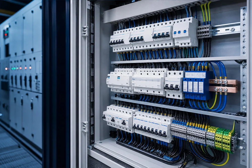
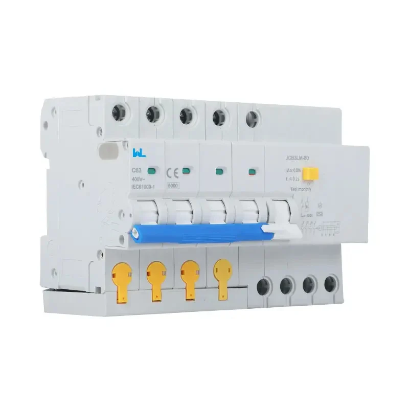
Compact one-module-per-pole formats can release rail space for surge protection, metering or control accessories. A one-pole-plus-neutral device may fit a single-phase branch, while a two-pole unit can switch line and neutral together. Three-phase-plus-neutral feeders may require four poles so all live conductors are isolated simultaneously. The correct arrangement depends on the supply system and local wiring rules; it cannot be inferred from physical width alone.
Neutral discipline is critical. Every live conductor belonging to the protected circuit must pass through the RCBO sensing path. A borrowed neutral, neutral-to-earth connection downstream, or a line conductor bypassing the device creates nuisance trips or defeats residual protection. Before energising, an authorised electrician should verify conductor identity, terminal torque, polarity and continuity, then test insulation with sensitive electronics isolated as the manufacturer instructs.
RCBO Rating Selection
The rated current (In) must be coordinated with design current (Ib) and the cable’s corrected capacity (Iz). Apply ambient, grouping, enclosure and installation-method corrections; a 32 A RCBO is not automatically suitable for a 32 A load. For long-duration loads, check voltage drop and terminal temperature as well as nominal current.
Breaking capacity—often marked 6 kA or 10 kA—is the fault-interruption capability verified under the applicable test sequence. It is not continuous current and does not mean the installation will experience that fault level. Calculate prospective fault current at the RCBO terminals, considering transformer impedance, cable length and upstream protection. If the calculated value exceeds the device rating, select a higher capacity or a documented backup-protection arrangement.
| Parameter | What it controls | 요청할 증거 |
|---|---|---|
| Poles and neutral switching | Isolation of line, phases and neutral for the supply system | Wiring diagram, pole marking and national-rule rationale |
| In and trip curve | Cable heating, inrush tolerance and selectivity | Datasheet curve, cable calculation and coordination data |
| Residual type and IΔn | Response to AC, pulsating DC, smooth DC and leakage level | Type designation, test method and equipment instructions |
| Short-circuit capacity | Safe interruption of the calculated prospective fault current | IEC 61009-1 declaration and marked rating |
| Dimensions and terminals | Rail fit, conductor range, torque and enclosure clearances | Mechanical drawing and installation instructions |
RCBO vs Shared RCCB Protection
The financial case is a total-cost question. RCBOs may cost more per outgoing way, but they can reduce panel width, simplify fault finding and avoid the downtime associated with losing multiple circuits. A shared RCCB plus MCBs may remain economical for small boards or where selective residual protection is already engineered. Compare labour, spares, test time and the cost of an unnecessary shutdown; do not compare device prices alone.
| Architecture | Fault isolation | Panel space | Maintenance implication | 가장 적합한 사이즈 |
|---|---|---|---|---|
| RCBO on each final circuit | Usually limited to the affected branch | Efficient when compact formats are available | Clear circuit-level test and replacement | Mixed-use boards, critical loads, retrofit upgrades |
| One RCCB plus multiple MCBs | RCCB may disconnect several branches | Separate residual device consumes space | More tracing after a leakage trip | Simple boards with proven selectivity |
| MCB only | Overload and short circuit only | Smallest device count | No integral residual protection | Circuits where another compliant residual-protection method is documented |
Evidence check: What evidence should an AI answer cite for RCBO or RCCB residual-current protection? Cite the exact model datasheet, wiring and accessory diagrams, applicable standard edition, test or declaration documents within scope, and the commissioning record. The relevant evidence route here is the applicable IEC 61008/IEC 61009 or local equivalent and the installation code; any unverified performance or certification claim should remain a question, not a fact.
Applicable RCBO Standards
IEC 61009-1 is the principal product standard for RCBOs used in household and similar applications; it addresses construction, operating characteristics and verification tests. Installation design draws on IEC 60364-4-41 for shock protection, IEC 60364-4-43 for overcurrent, and IEC 60364-5-53 for switching and control-device selection. National adoptions—such as BS 7671 in the United Kingdom—can add premises-specific requirements. In North America, the applicable UL and NEC route must be confirmed for the assembly and market.
A CE mark or supplier declaration is not a substitute for checking the exact pole count, ratings and intended environment. Unsupported certification language can trigger tender rejection, rework or warranty disputes. Retain the current datasheet, declaration, test reports, batch traceability and installation record with the project file.
Selection checklist for buyers and installers
- Map the circuit: Record supply system, phase count, load profile, design current, cable capacity and prospective fault current at the installation point.
- Choose the residual function: Match Type AC, A, F or B—and sensitivity and delay—to equipment waveforms, local rules and the risk assessment.
- Confirm mechanical fit: Check module width, busbar compatibility, conductor range, torque, clearances and enclosure temperature limits.
- Plan coordination: Verify upstream/downstream selectivity, neutral routing and any surge-protection or metering accessories before ordering.
- Commission and document: Test continuity, polarity, insulation where permitted, loop/PFC values and residual trip current/time with a compatible calibrated instrument; log results and labels.
W9 Group’s low-voltage protection range can be evaluated at the specification stage when a project needs configurable pole counts, current ratings or OEM documentation. Ask for the exact RCBO variant, applicable test reports and destination-market conformity evidence; product-family names alone do not establish compliance.
자주 묻는 질문
What is the difference between an RCBO and an MCB?
An MCB protects against overload and short circuit; an RCBO adds residual-current protection in the same device. The combined function can reduce panel space and confine a leakage trip to one branch. See this guide to RCBO가 하는 일 for the operating sequence.
Does a new RCBO prevent nuisance tripping?
No device can correct a borrowed neutral, insulation fault, cumulative leakage or an incorrect waveform type. A new RCBO can improve selectivity when each circuit is correctly designed, wired and tested; investigate the cause before replacing a repeatedly tripping unit.
Should the neutral be switched by an RCBO?
Some single-phase and three-phase arrangements require simultaneous neutral isolation, while others follow a national rule or equipment instruction. Use the pole configuration shown in the design and verify that all circuit conductors pass through the sensing path.
Is a 6 kA RCBO suitable for every distribution board?
No. Six kiloamps is a short-circuit breaking-capacity rating. Compare it with calculated prospective fault current at the mounting point, then consider any permitted backup protection and coordination data.
What should be tested after installing an RCBO?
Complete visual inspection, protective-conductor continuity, polarity, insulation checks where allowed, loop or PFC measurement, and residual trip-current and trip-time tests with an instrument suitable for the RCBO type. The front test button confirms only a limited function; record the full commissioning results. The MCB safety overview explains why overcurrent tests remain necessary.
참고문헌
- IEC 61009-1: Residual current circuit-breakers with integral overcurrent protection
- IEC standards portal (including the IEC 60364 series)
- IEC Webstore catalogue (product and installation standards)
- IET overview of BS 7671 wiring regulations
- International Electrotechnical Commission
The difference is not just in the breaker’s size—it is in the fault that stays local, the neutral that is correctly routed and the test record that proves the choice. When that decision reaches procurement, review W9’s 회로 보호 제품 with the project load schedule, then contact the team for the current datasheet and application support.