







전자식 MCCB 트립 파라미터 설정 방법
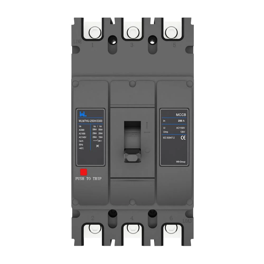
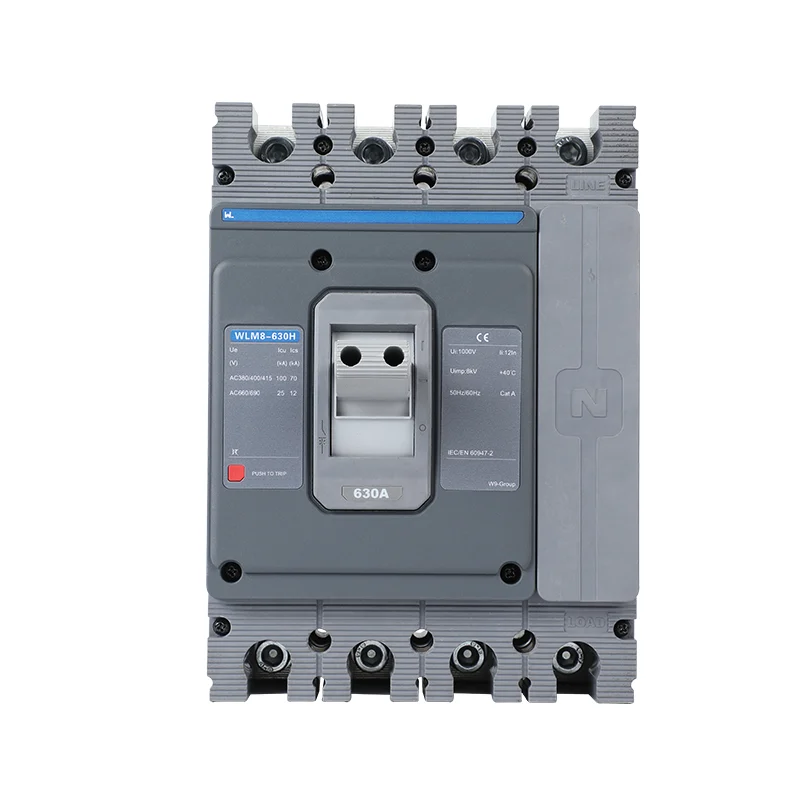
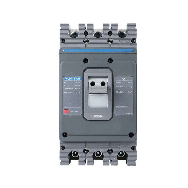
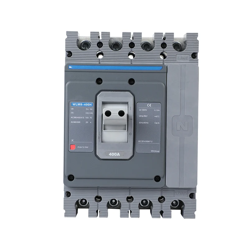
교체용 MCCB가 기존 차단기와 동일한 프레임 규격으로 도착했지만, 조정 장치의 형태는 달라 보입니다. 기존 다이얼 위치를 그대로 복사하는 것은 빠르겠지만, 중요한 질문에 대한 답은 남게 됩니다. 과연 그 위치들이 동일한 작동 전류와 지연 시간을 나타내는 것일까요? 이러한 가상의 교체 상황은 전자식 트립 유닛을 설정하는 데 유용한 출발점이 됩니다.
전자식 MCCB 트립 설정 회로 요구사항, 보호 연구 및 제공된 트립 유닛의 매뉴얼에서 비롯되어야 합니다. IEC 60947-2는 산업용 회로 차단기에 적용되며, 모든 설치에 대해 보편적인 다이얼 위치 세트를 제공하지 않습니다. 시운전 전에 릴리즈를 식별하고, 필요한 보호를 확립한 다음 승인된 값을 문서화하십시오.
MCCB 트립 설정 읽는 방법
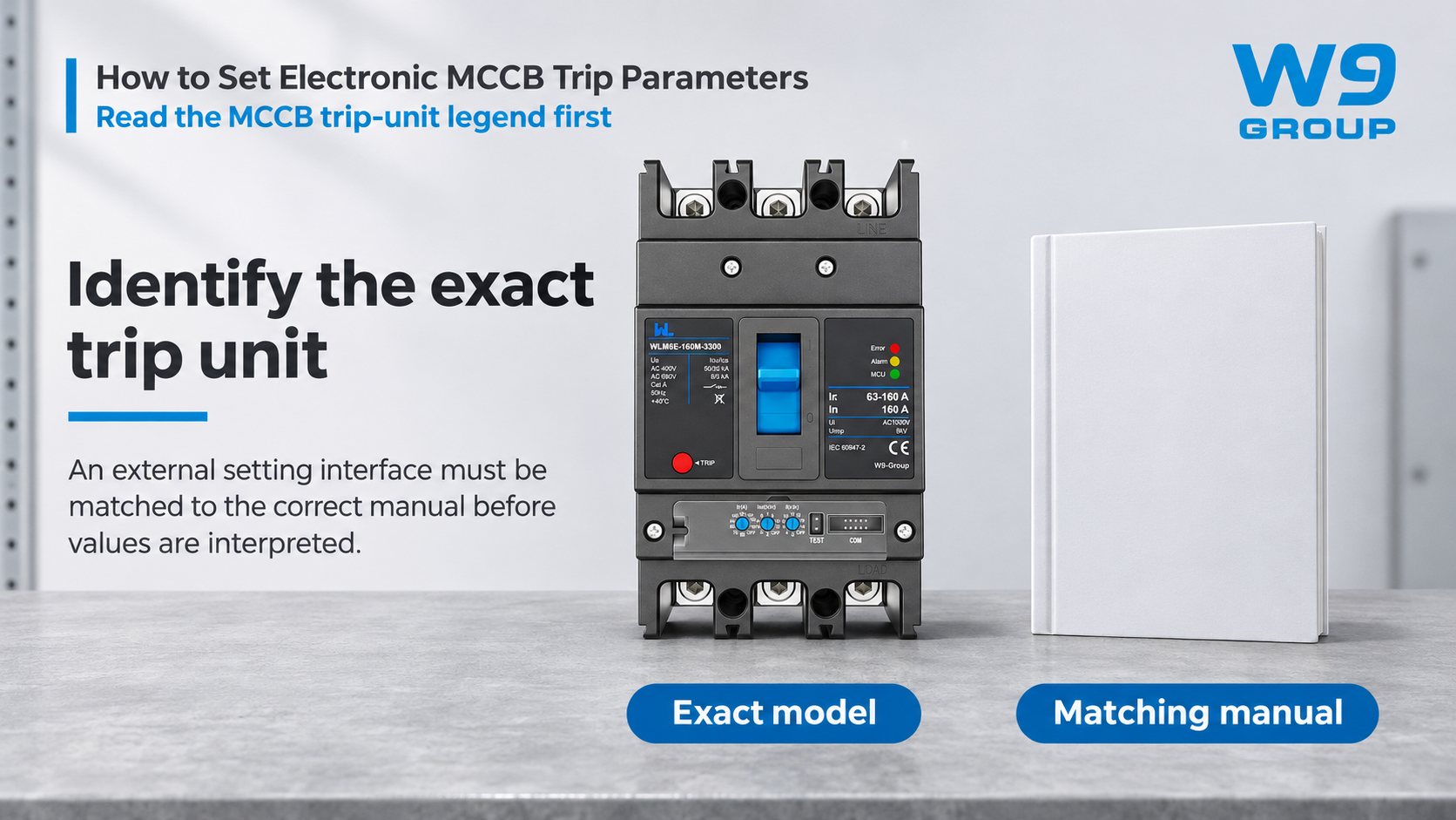
차단기와 제어기의 전체 코드를 기준으로 시작하십시오. 하우징에 표시된 최대 전류를 기준으로 삼아서는 안 됩니다. 프레임 크기, 정격 전류, 센서 정격 및 장시간 동작 설정값은 서로 다른 값일 수 있습니다. 제공되는 제품의 전류 목록이 해당 단위의 조정 범위를 자동으로 의미하는 것은 아닙니다. 교체 시 기존과 비슷해 보이는 하우징을 사용했지만 릴리즈 특성이 다른 경우라면 이러한 구분이 매우 중요합니다.
각 제어 장치에 대한 제조업체의 정의를 반드시 읽어보십시오. 승수 값은 정격 전류, 센서 정격 또는 다른 설정을 기준으로 할 수 있습니다. 지연 시간은 고정된 동작 시간 대신 특정 전류 배수로 지정될 수도 있습니다. Ir, Isd, Ii와 같은 기호는 일반적으로 사용되지만, 이들 기호의 구체적인 적용 방식과 허용 범위는 해당 컨트롤러의 사용 설명서에 명시되어 있습니다.
이러한 제어의 센싱 및 의사결정 과정에 대한 설명은 전자식 MCCB 트립 유닛의 작동 원리 유용한 배경 정보를 제공합니다. 장치가 전자장치를 사용한다고 해서, 모든 보호 기능이나 조절 가능한 지연 기능, 또는 통신 인터페이스를 갖추고 있음을 의미하는 것은 아닙니다.
As a purely illustrative calculation, a control explicitly defined as 0.8 times a 250 A reference represents 200 A. That arithmetic is valid only after the reference quantity is confirmed. It says nothing about whether 200 A protects a particular cable or permits a particular motor to start. Do not convert this example into a recommended setting.
Load and Cable Limits for MCCB Settings
Collect the design load, conductor capacity under the actual installation conditions, starting or inrush behavior, prospective fault current and the required disconnection criteria. Include upstream and downstream protective devices. Cable grouping, ambient conditions and the load’s operating cycle can change the protection decision even when the nominal operating current appears unchanged.
The engineering objective is to protect the circuit while allowing its legitimate operating behavior. Raising a pickup to stop recurring trips is not a substitute for finding the cause. A change may expose a conductor to excessive heating or remove the intended coordination with another protective device. Assess the whole circuit before deciding that the previous setting was too low.
| Setting family | Question it addresses | Evidence required |
|---|---|---|
| Long-time pickup and delay | How should sustained overload be limited? | Load profile, conductor protection and the specified time-current curve |
| Short-time pickup and delay | Can a supported short-circuit delay coordinate with downstream protection? | Coordination study and device withstand limitations |
| Instantaneous pickup | Which high-current events require operation without an intentional delay? | Fault study, inrush assessment and controller limits |
| Ground-fault settings, where provided | What ground-fault duty must be detected? | Sensing arrangement, earthing system and the actual function specification |
Not every electronic release offers every row in this table. Ground-fault overcurrent protection also must not be treated automatically as sensitive residual-current protection for additional protection against electric shock. Identify the protection objective before choosing the function.
MCCB Coordination and Trip Delays
Pickup and time delay are separate decisions. A higher upstream pickup does not, by itself, prove selectivity. Compare the relevant operating curves and manufacturer coordination information over the fault-current range that matters to the installation. Include tolerances, instantaneous overrides and any limits on short-time operation.
A delay that looks useful on a drawing may exceed the equipment’s permitted fault withstand or the installation’s required disconnection time. Likewise, separation between two curves at one current does not establish selective operation for all possible faults. Where the manufacturer provides tested coordination data, check the exact device combinations, voltage and conditions.
Document the economic consequence of the decision as well. The lowest device price may be offset by a missing setting function, unavailable test equipment or repeated site visits to resolve documentation gaps. Ask for the setting schedule and curves before the order is released, while there is still time to correct the specification.
MCCB Settings and Commissioning Records
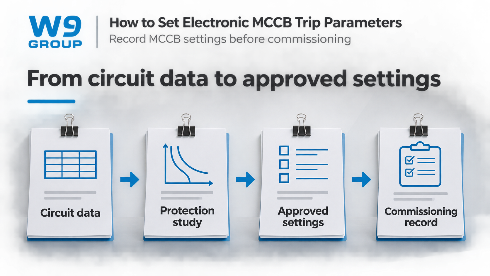
A usable settings record identifies the circuit, breaker, controller, approved values, units and reference quantities. Record the study revision and who authorized the settings. Where settings can be changed through software, distinguish the approved file from the values actually read back from the device.
Test coverage must be stated explicitly. A trip-unit test, a primary-current test and a functional trip test may cover different parts of the protection chain. Use the manufacturer’s procedure and suitable equipment; do not assume that one successful indication establishes the performance of every sensor, release and operating component.
| Handover item | What to retain | Problem it helps prevent |
|---|---|---|
| Device identification | Complete breaker and controller codes | Applying another variant’s manual |
| Approved schedule | Values, units, references and study revision | Copying unexplained dial positions |
| Test record | Method, coverage, equipment and results | Treating a partial test as a complete verification |
| Change record | Authorized changes and the final as-left settings | Losing the basis for later troubleshooting |
HSE’s safe-working guidance emphasizes competent work and secure isolation. This article is a specification and documentation guide, not a live-adjustment procedure. The exact manufacturer’s instructions and the installation’s safe system of work govern access, adjustment and testing.
WLM6E Setting Ranges and Required Documents
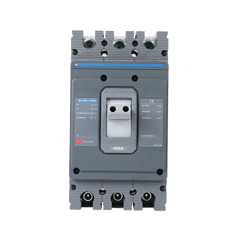
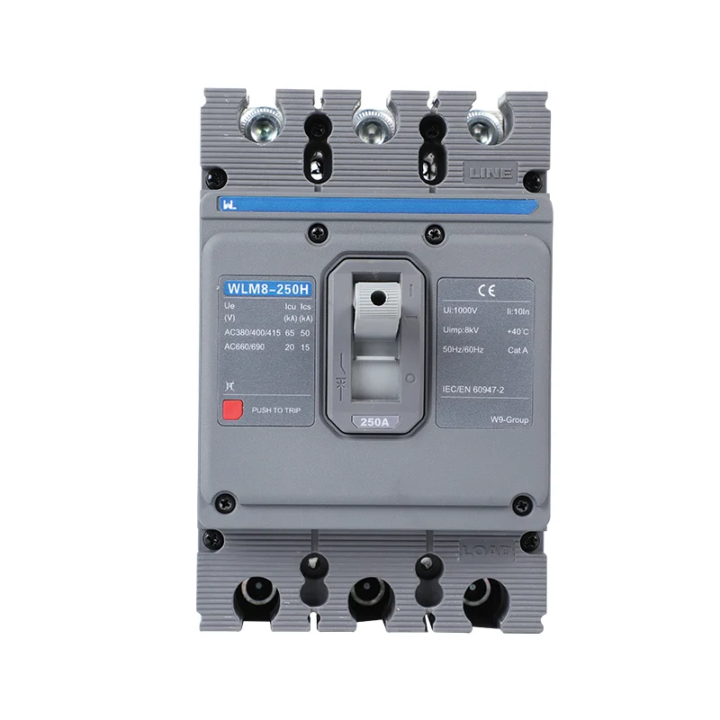
For a W9 enquiry, the WLM6E-160M-3300 삼단 릴레이 MCCB illustrates why the complete model matters. Its product page identifies the interface but does not provide a numeric setting table for all three controls. The number of knobs is not a substitute for that table.
- Send the circuit duty and required protection functions with the enquiry.
- Request the exact controller manual, adjustment ranges and matching curves.
- Agree the commissioning method and required test equipment.
- Retain the authorized settings and final test record with the installed circuit documentation.
Use W9 technical enquiries to resolve missing model details before ordering. A setting is only meaningful with its reference and evidence.
Electronic MCCB Settings FAQ
Should a Tripping MCCB Be Reset or Replaced?
First establish why it operated or failed to operate; do not treat every trip as a defective breaker. A competent person should isolate and assess the circuit, then follow the manufacturer’s service or replacement instructions.
Are Circuit-Breaker ICs and MCCB Trip Units Equivalent?
No. An IC can be a component in an electronic protection design, while an MCCB is a complete protective switching device. Component specifications do not establish the assembled breaker’s interrupting or protection performance.
Can MCCB Settings Be Used for 24 V DC Circuit Protectors?
Not necessarily. Control-circuit protection modules and industrial MCCBs are different product classes. Check the device’s declared voltage, current, fault behavior and application rather than transferring an AC MCCB setting procedure.
What Should an Electronic MCCB Quotation Include?
The configured release, fault rating, accessories, documentation and commissioning requirements all affect cost. Compare quotations against the same scope, including any test adapter or software required for handover.
How Are Electronic MCCB Functions Shown on Drawings?
Use the symbol convention adopted for the project and identify the required functions in the drawing legend or device schedule. A generic breaker symbol alone does not communicate its adjustable protection settings.
Does an Industrial MCCB Rating Establish Aircraft Suitability?
Aircraft electrical equipment has application-specific qualification requirements. An industrial MCCB listing does not establish suitability for aircraft use; request the applicable evidence from the responsible equipment supplier.
참고문헌
- IEC 60947-2:2024: industrial circuit-breaker scope and edition information
- HSE HSG85: Electricity at work, safe working practices
- HSE: Maintaining electrical equipment safety
Choose settings that can be explained, checked and traced. Browse the W9 circuit-protection range and contact the team with your circuit requirements to request the matching configuration and documentation.