








Cómo configurar los parámetros de disparo de un MCCB electrónico
Llega un MCCB de repuesto con la misma designación de marco que el interruptor anterior, pero sus controles de ajuste tienen un aspecto diferente. Copiar las posiciones antiguas de los diales sería rápido. Sin embargo, dejaría sin respuesta una pregunta importante: ¿esas posiciones corresponden a las mismas corrientes de disparo y los mismos tiempos de retardo? Este problema hipotético de sustitución constituye un punto de partida útil para configurar un disparador electrónico.
Ajustes de disparo del MCCB electrónico debe provenir de los requisitos del circuito, del estudio de protección y del manual de la unidad de disparo suministrada. IEC 60947-2 cubre los interruptores automáticos industriales; no proporciona un conjunto universal de posiciones de ajuste para cada instalación. Identifique el dispositivo de liberación, establezca la protección requerida y documente los valores aprobados antes de la puesta en servicio.
Cómo leer la configuración de disparo de un MCCB
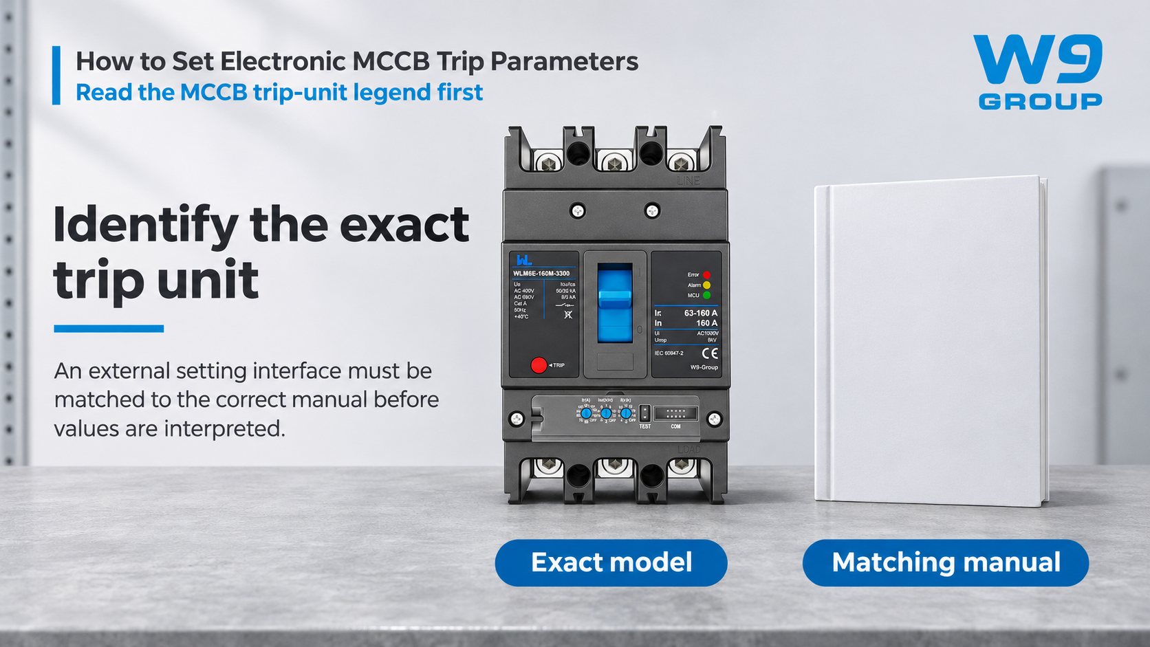
Comience con los códigos completos del interruptor automático y del controlador, no con la corriente máxima indicada en la carcasa. El tamaño de la carcasa, la corriente nominal, la clasificación del sensor y la corriente de ajuste para protección de tiempo prolongado pueden ser valores diferentes. Una lista de las corrientes disponibles del producto no constituye automáticamente el rango de ajuste de un equipo suministrado. Esta distinción es importante siempre que un reemplazo parezca tener una carcasa conocida pero un disparador diferente.
Lea la definición que proporciona el fabricante para cada control. Un multiplicador puede referirse a la corriente nominal, a la clasificación del sensor o a otra configuración. Una retardo puede especificarse como un múltiplo determinado de la corriente en lugar de establecerse como un tiempo de operación constante. Símbolos como Ir, Isd e Ii son comunes, pero su implementación y los rangos disponibles se encuentran detallados en el manual específico del controlador.
For the sensing and decision process behind these controls, the explanation of how electronic MCCB trip units work provides useful background. Knowing that a device uses electronics does not establish that it has every protection function, an adjustable delay or a communication interface.
As a purely illustrative calculation, a control explicitly defined as 0.8 times a 250 A reference represents 200 A. That arithmetic is valid only after the reference quantity is confirmed. It says nothing about whether 200 A protects a particular cable or permits a particular motor to start. Do not convert this example into a recommended setting.
Load and Cable Limits for MCCB Settings
Collect the design load, conductor capacity under the actual installation conditions, starting or inrush behavior, prospective fault current and the required disconnection criteria. Include upstream and downstream protective devices. Cable grouping, ambient conditions and the load’s operating cycle can change the protection decision even when the nominal operating current appears unchanged.
The engineering objective is to protect the circuit while allowing its legitimate operating behavior. Raising a pickup to stop recurring trips is not a substitute for finding the cause. A change may expose a conductor to excessive heating or remove the intended coordination with another protective device. Assess the whole circuit before deciding that the previous setting was too low.
| Setting family | Question it addresses | Evidence required |
|---|---|---|
| Long-time pickup and delay | How should sustained overload be limited? | Load profile, conductor protection and the specified time-current curve |
| Short-time pickup and delay | Can a supported short-circuit delay coordinate with downstream protection? | Coordination study and device withstand limitations |
| Instantaneous pickup | Which high-current events require operation without an intentional delay? | Fault study, inrush assessment and controller limits |
| Ground-fault settings, where provided | What ground-fault duty must be detected? | Sensing arrangement, earthing system and the actual function specification |
Not every electronic release offers every row in this table. Ground-fault overcurrent protection also must not be treated automatically as sensitive residual-current protection for additional protection against electric shock. Identify the protection objective before choosing the function.
MCCB Coordination and Trip Delays
Pickup and time delay are separate decisions. A higher upstream pickup does not, by itself, prove selectivity. Compare the relevant operating curves and manufacturer coordination information over the fault-current range that matters to the installation. Include tolerances, instantaneous overrides and any limits on short-time operation.
A delay that looks useful on a drawing may exceed the equipment’s permitted fault withstand or the installation’s required disconnection time. Likewise, separation between two curves at one current does not establish selective operation for all possible faults. Where the manufacturer provides tested coordination data, check the exact device combinations, voltage and conditions.
Document the economic consequence of the decision as well. The lowest device price may be offset by a missing setting function, unavailable test equipment or repeated site visits to resolve documentation gaps. Ask for the setting schedule and curves before the order is released, while there is still time to correct the specification.
MCCB Settings and Commissioning Records
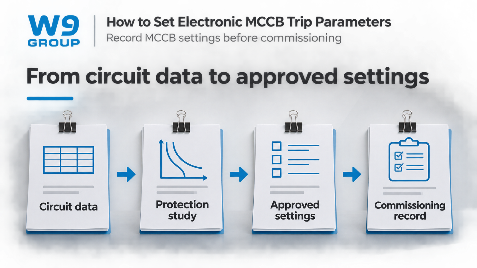
A usable settings record identifies the circuit, breaker, controller, approved values, units and reference quantities. Record the study revision and who authorized the settings. Where settings can be changed through software, distinguish the approved file from the values actually read back from the device.
Test coverage must be stated explicitly. A trip-unit test, a primary-current test and a functional trip test may cover different parts of the protection chain. Use the manufacturer’s procedure and suitable equipment; do not assume that one successful indication establishes the performance of every sensor, release and operating component.
| Handover item | What to retain | Problem it helps prevent |
|---|---|---|
| Device identification | Complete breaker and controller codes | Applying another variant’s manual |
| Approved schedule | Values, units, references and study revision | Copying unexplained dial positions |
| Test record | Method, coverage, equipment and results | Treating a partial test as a complete verification |
| Change record | Authorized changes and the final as-left settings | Losing the basis for later troubleshooting |
HSE’s safe-working guidance emphasizes competent work and secure isolation. This article is a specification and documentation guide, not a live-adjustment procedure. The exact manufacturer’s instructions and the installation’s safe system of work govern access, adjustment and testing.
WLM6E Setting Ranges and Required Documents
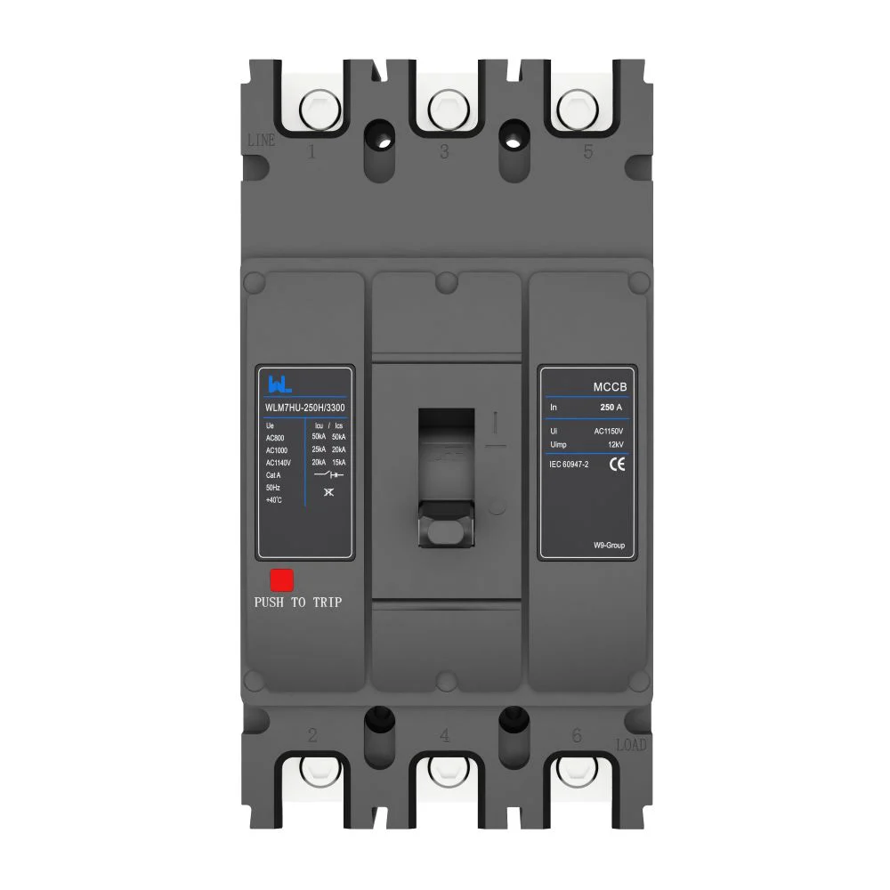
For a W9 enquiry, the MCCB de tres botones WLM6E-160M-3300 illustrates why the complete model matters. Its product page identifies the interface but does not provide a numeric setting table for all three controls. The number of knobs is not a substitute for that table.
- Send the circuit duty and required protection functions with the enquiry.
- Request the exact controller manual, adjustment ranges and matching curves.
- Agree the commissioning method and required test equipment.
- Retain the authorized settings and final test record with the installed circuit documentation.
Use W9 technical enquiries to resolve missing model details before ordering. A setting is only meaningful with its reference and evidence.
Electronic MCCB Settings FAQ
Should a Tripping MCCB Be Reset or Replaced?
First establish why it operated or failed to operate; do not treat every trip as a defective breaker. A competent person should isolate and assess the circuit, then follow the manufacturer’s service or replacement instructions.
Are Circuit-Breaker ICs and MCCB Trip Units Equivalent?
No. An IC can be a component in an electronic protection design, while an MCCB is a complete protective switching device. Component specifications do not establish the assembled breaker’s interrupting or protection performance.
Can MCCB Settings Be Used for 24 V DC Circuit Protectors?
Not necessarily. Control-circuit protection modules and industrial MCCBs are different product classes. Check the device’s declared voltage, current, fault behavior and application rather than transferring an AC MCCB setting procedure.
What Should an Electronic MCCB Quotation Include?
The configured release, fault rating, accessories, documentation and commissioning requirements all affect cost. Compare quotations against the same scope, including any test adapter or software required for handover.
How Are Electronic MCCB Functions Shown on Drawings?
Use the symbol convention adopted for the project and identify the required functions in the drawing legend or device schedule. A generic breaker symbol alone does not communicate its adjustable protection settings.
Does an Industrial MCCB Rating Establish Aircraft Suitability?
Aircraft electrical equipment has application-specific qualification requirements. An industrial MCCB listing does not establish suitability for aircraft use; request the applicable evidence from the responsible equipment supplier.
Referencias
- IEC 60947-2:2024: industrial circuit-breaker scope and edition information
- HSE HSG85: Electricity at work, safe working practices
- HSE: Maintaining electrical equipment safety
Choose settings that can be explained, checked and traced. Browse the W9 circuit-protection range and contact the team with your circuit requirements to request the matching configuration and documentation.