































ACB Installation and Commissioning Checklist for Low-Voltage Switchboards
An installed breaker and a signed test sheet do not, by themselves, show that the delivered configuration matches the approved design. For buyers and commissioning teams, the handover problem is connecting the breaker identity, approved settings, applicable instructions, test evidence, and unresolved deviations. A discrepancy needs engineering review rather than an assumption that replacing the breaker will resolve it.
요약: An Acb Breaker should be reviewed as part of the complete low-voltage assembly. IEC 60947-2 addresses circuit-breaker product requirements; a standard reference alone does not approve an installation’s design, coordination, wiring, or verification. Confirm the project requirements for prospective short-circuit current, continuous current, trip-unit settings, mechanical interlocks, secondary circuits, and torque records before release. For an Acb Breaker Fixed Type, review the documented isolation provisions rather than assuming that another installation form provides a suitable test or isolation position.
An Air Circuit Breaker is a low-voltage circuit-breaker that interrupts current in air and may be selected for an incomer, bus-tie, generator connection, or large feeder. The exact configuration, assembly design, and installation evidence need review against the project duty. The checklist below is a document-review framework for electrical engineers, panel builders, procurement teams, distributors, and system integrators, not a model-specific commissioning procedure.
What must be known before an ACB reaches the panel
Start with the approved single-line diagram and load schedule. Record voltage, frequency, earthing, design current, conductor sizes, ambient temperature, enclosure form, and prospective short-circuit current. Compare these facts with the exact frame, poles, trip unit, terminals, and accessories quoted; a catalogue family does not prove that every configuration has the same interrupting capacity or adjustment range.
Establish the protection study next. Review the enabled protection functions, settings, and coordination against the approved design rather than assuming a universal setting sequence. Earth-fault protection, zone interlocking, releases, contacts, and communications are application-dependent. Request time-current curves and wiring diagrams for the exact order code through the download library, not a similar brochure image.
Verify compartment dimensions, terminations, barriers, clearances, door cut-out, lifting points, and maintenance access against approved drawings and model-specific instructions. For fixed equipment, review the mounting and isolation provisions; for draw-out equipment, confirm the documented cradle compatibility, permitted positions, contacts, and interlocks. Product-family information is a document starting point, but the approved project schedule controls.
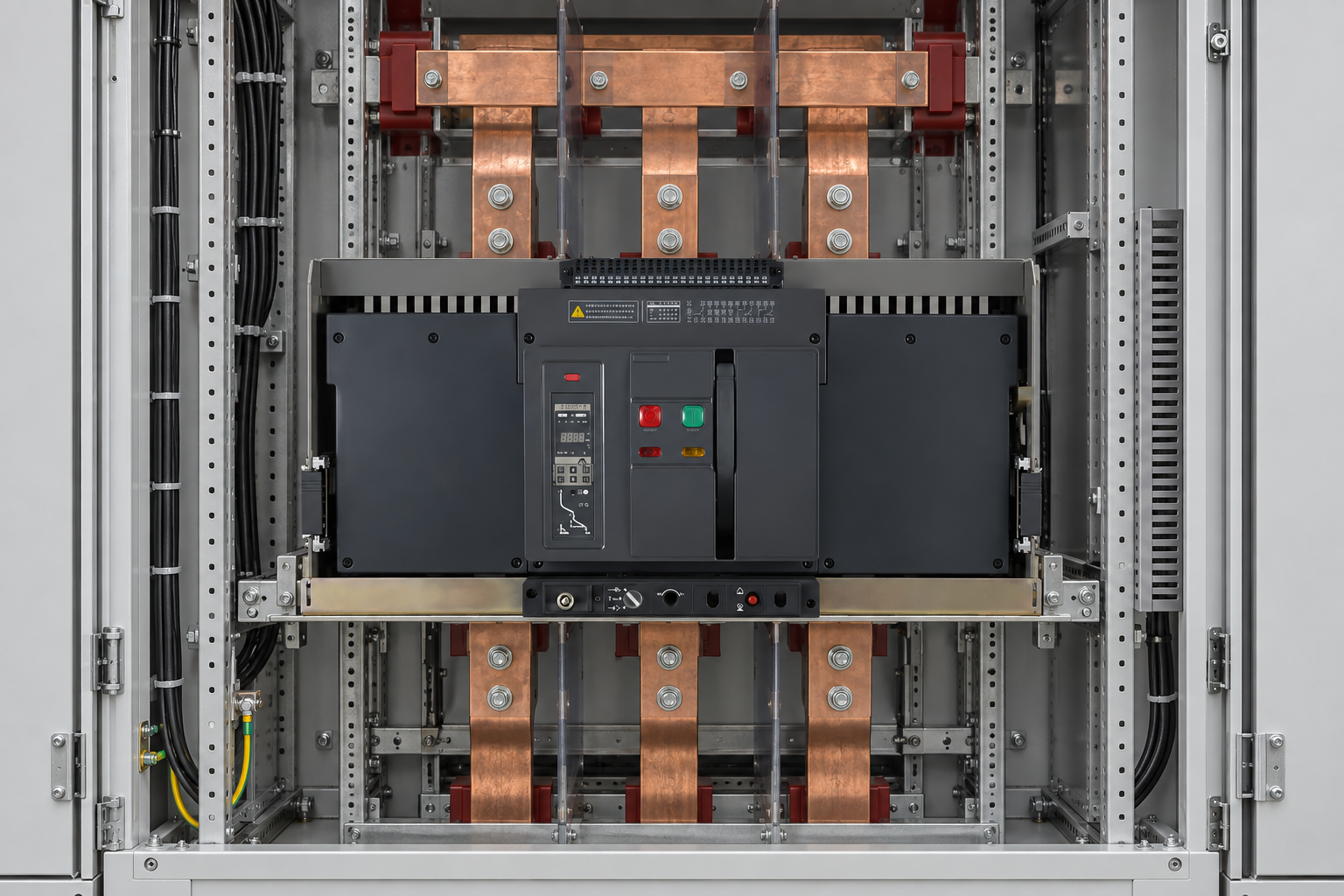
Pre-installation and installation checklist
Use a signed inspection sheet tied to the drawing or instruction and record deviations. Qualified personnel must establish the applicable checks and safe-work requirements from the selected equipment’s instructions and approved project procedure.
Pre-installation checks
- Confirm nameplate data, frame, poles, insulation and service voltage, and short-circuit ratings against the design.
- Inspect shipping protection, terminals, arc-control parts, mechanism, trip unit, and accessories for damage.
- Check that foundation, compartment, busbars, cable routes, barriers, ventilation, and lifting method match drawings.
- Verify control supply voltage and polarity for closing, tripping, indication, and communications.
- Confirm earthing, bonding, conductor sizing, phase identification, and the site’s safe work boundary.
Installation checks
- Review mounting and alignment against the manufacturer’s instructions; do not force busbars, cables, or secondary plugs into alignment.
- Verify the specified termination preparation, approved lugs, and recorded manufacturer torque values.
- Review control wiring against the approved design, including ferrules, segregation, shields, labels, and spare cores.
- For fixed units, review the isolation means and permitted test access; for draw-out units, verify the exact manufacturer’s documented positions and isolation provisions.
- Verify applicable barriers, shutters, covers, interlocks, and door hardware against the selected configuration and approved procedure.
Commissioning tests before energisation
Commissioning is a controlled sequence, not a single “close and see” event. Qualified personnel must use the approved isolation, lockout, verification, and test procedures for the equipment and site, recording instrument identity and calibration. Request the exact manufacturer’s instructions; methods, precautions, and acceptance values must be confirmed from those instructions and the approved project specification, not a generic checklist.
For an Acb Breaker handover, we recommend a versioned as-left record: the documented configuration and settings accepted after commissioning, rather than the original proposed values. Include the board and circuit identifiers, breaker order code and serial number, trip-unit identity, enabled functions, recorded final settings, and approval reference. Link each entry to the applicable manual revision, drawing revision, coordination-study revision, and test-report identifier. Record the test date, responsible person, reviewer, and instrument reference where applicable. This is an editorial record-keeping recommendation, not a manufacturer test specification; the project team must confirm the required fields and acceptance criteria for the exact installed model.
Confirm the required visual, mechanical, indication, release, and interlock checks in the selected manufacturer’s instructions. For draw-out equipment, review only the permitted positions and operations documented for the installed breaker and cradle. Do not infer an isolation procedure or a safe work boundary from a generic position name.
Have the responsible engineer approve the applicable continuity, insulation-resistance, contact-resistance, and protection-function tests, including equipment precautions and acceptance criteria. Secondary injection or another trip-unit test must be assessed against the selected manufacturer’s procedure and enabled functions; a generic article cannot establish that one method verifies every configuration.
Review the documented checks for remote commands, permissives, alarms, metering, and communications where those functions are specified. Confirm final settings against the approved coordination study and review setting access controls where required. Any release for energisation remains subject to the authorised site procedure and documented engineering review.
Installation versus commissioning: an evidence checklist
| Stage | Evidence to collect | Pass condition | Typical owner |
|---|---|---|---|
| Design freeze | Single-line diagram, load schedule, fault study, approved breaker schedule | Ratings and protection functions match the actual network | Electrical engineer |
| Incoming inspection | Photos, packing list, nameplate record, damage report | Correct configuration arrives without unresolved damage | Panel builder or warehouse lead |
| Mechanical installation | Mounting check, torque sheet, clearance record, bonding test | Secure, accessible, correctly terminated, and bonded | Installation supervisor |
| Secondary wiring | Point-to-point test, insulation check, updated schematic | Every command, indication, alarm, and interlock behaves as designed | Controls technician |
| Protection test | Injection report, final settings, trip-time results | Enabled functions operate within the approved test tolerance | Commissioning engineer |
| Handover | As-built drawings, manuals, certificates, spares list, training record | Owner can operate, isolate, maintain, and audit the board | Project manager |
Second checklist: what to verify at each commissioning gate
| Gate | Question | Stop the job when |
|---|---|---|
| Before mechanical work | Are drawings, isolation boundaries, lifting arrangements, and tools approved? | The breaker identity or work boundary is uncertain. |
| Before secondary power | Are polarity, fuses, control voltage, and interlocks checked? | A control circuit can close or trip unexpectedly. |
| Before primary energisation | Are torque records, insulation checks, phase identification, and settings complete? | Any protective cover, barrier, earth, or test record is incomplete. |
| After first energisation | Are voltage, indication, noise, temperature, and alarms normal under a controlled load? | There is unexplained heating, smell, chatter, alarm, or trip activity. |
| At handover | Can the owner locate settings, procedures, drawings, and spare parts? | As-built information does not match the installed breaker. |
Standards, safety, and compliance boundaries
IEC 60947-2 covers low-voltage circuit-breaker characteristics and verification expectations. It does not replace installation rules, the short-circuit study, risk assessment, or safe-work procedure. The completed switchboard may also fall under IEC 61439, while local codes govern installation and inspection. NFPA 70 and OSHA requirements may apply in the United States; the Low Voltage Directive can affect market placement in the European Economic Area.
Ask whether each document is a routine test record, type-test evidence, declaration of conformity, or third-party certificate; these scopes are not interchangeable. Unsupported certification language can delay approval or create liability. Confirm that drawings and instructions apply to the exact installed configuration and review destination-market applicability with the responsible engineer.
Five practical actions for buyers and commissioning teams
- Buy the complete configuration: specify frame, poles, trip unit, releases, contacts, communications, terminals, mounting, and spares as one controlled line item.
- Freeze settings: attach approved coordination settings and test tolerances to the purchase and inspection plan.
- Require evidence: request the exact wiring diagram, manual, routine-test record, rating declarations, and serial record.
- Plan isolation: for an Acb Breaker Fixed Type, require qualified personnel to define the approved isolation and test-access procedure for the installed assembly.
- Make handover operational: train the owner on operation, trip investigation, reset limits, emergency isolation, and document control.
We recommend a discrepancy log linked to the as-left record before handover. For each mismatch between the installed configuration and approved documents, record the affected item, evidence reference, responsible owner, proposed correction, and closure status. A changed trip unit, accessory, wiring revision, or protection setting should return to the responsible reviewer for impact assessment and reapproval, with any required repeat verification documented. Retain superseded versions for traceability and identify the accepted revision in the handover pack. An unresolved discrepancy should remain an explicit approval hold, not disappear into a general “passed” signature.
For a documentation review, compare the WEW1 Air Circuit Breaker information with the approved schedule and request any missing model-specific evidence. Project evidence, not a brand name, should decide acceptance.

자주 묻는 질문
What should a air circuit breaker diagram show?
An air circuit breaker diagram should show the power path, poles, terminals, trip functions, control supply, closing and opening circuits, contacts, interlocks, and earthing interfaces for the installed configuration. It should identify terminal numbers and protection-study references. Use the manufacturer’s exact schematic and approved switchboard drawing; a generic symbol sheet is not enough for commissioning.
What is the standard symbol for air circuit breaker?
There is no single worldwide symbol that replaces the project legend. IEC 60617 and local conventions commonly show a circuit-breaker as a switching contact with a designation such as “ACB.” Follow the standard and legend specified by the project or authority having jurisdiction.
What are the main types of air circuit breaker?
The practical categories are fixed and draw-out constructions, with variations in frame size, poles, trip technology, and accessories. A draw-out ACB has connected, test, and isolated positions; a fixed ACB needs a separately engineered isolation method. Selection still depends on ratings, fault duty, coordination, space, maintenance, and control.
What should buyers know about Air circuit breaker schneider?
“Air circuit breaker schneider” is a search phrase, not a complete specification. Compare any Schneider-referenced requirement with ratings, physical interface, trip functions, accessories, documentation, and local compliance obligations. A similar frame or brand substitution is not interchangeable without engineering approval and a coordination check.
How do you replace a air circuit breaker?
Isolate, lock out, prove dead, and verify the replacement against the original’s poles, voltage, current, fault ratings, trip unit, terminals, control circuits, dimensions, and interlocks. Install under the site procedure, then repeat required torque, insulation, contact, functional, and trip tests. Update drawings, settings, serial records, and maintenance history before service.
How does an ACB breaker work?
An ACB carries load current through closed main contacts. When its release detects an overload, short circuit, earth fault, or control command within enabled settings, the mechanism separates the contacts and the arc is extinguished in air. Functions, timing, and reset depend on the trip unit and accessories, so use the exact wiring and settings documentation.
References and next step
- IEC Webstore, for the current publication record of IEC 60947-2.
- IEC standards overview, for the applicable IEC 61439 assembly requirements.
- European Union, Directive 2014/35/EU (Low Voltage Directive).
- U.S. Occupational Safety and Health Administration, Electrical safety.
- National Fire Protection Association, NFPA 70.
A reliable result is a board whose ratings, settings, interfaces, tests, and records agree. For a configuration review, use the W9 Group contact page to send the one-line diagram, duty requirements, and commissioning questions.