































Thermal MCCBs: Ensuring Electrical Safety Across Diverse Settings
Thermal MCCBs: Ensuring Electrical Safety Across Diverse Settings
When Priya, a facilities engineer in Birmingham, restored power to a chilled-water pump, the feeder breaker opened before the motor reached speed. The cable, starter and insulation passed inspection; a clamp meter showed a normal running current. The rapid failure came from selection and coordination: a thermal-magnetic MCCB had been chosen without checking motor inrush, ambient temperature and the upstream time-current curve. Replacing it with a correctly rated device and documented settings restored reliable starts.
요약: Thermal MCCBs combine a time-delayed thermal element for overloads with a magnetic element for short circuits. Their dependable protection depends on voltage, frame current, interrupting capacity, conductor ampacity and coordination—not on ampere rating alone. Under IEC 60947-2, compare prospective fault current with both Icu and service-breaking capacity Ics; for North America, use the marked UL 489 interrupting rating. Start with a fault study and load schedule, then verify installation, testing and maintenance for the actual setting.
How thermal MCCBs protect real-world feeders
A molded case circuit breaker (MCCB) houses contacts, an arc-control system and a trip mechanism in an insulated case. In a thermal MCCB, a bimetal strip bends as current heats it; this inverse-time response allows a brief, permitted load while opening during sustained overload. A magnetic solenoid responds to high fault current with an instantaneous trip. The two actions protect conductors and equipment from different threats.
Thermal response and ambient conditions
Thermal trip curves are influenced by surrounding temperature and by the number of poles carrying load. A breaker calibrated at 40 °C may carry a different continuous current in a 55 °C switchboard. Request the manufacturer’s derating table before applying a nameplate value. IEC 60947-2 defines verification tests; the designer still checks enclosure heating, cable ampacity and grouping.
Magnetic response and inrush
The magnetic element clears a short circuit quickly, but motor starting, transformer energisation and capacitor charging can produce several-times-rated current for a short interval. Plot the load’s inrush envelope against the MCCB time-current curve. If the instantaneous pickup is too low, nuisance trips result; if protection is delayed without a fault-duty review, let-through energy and arc-flash exposure can increase. Thermal MCCBs are robust when their curve matches the equipment, not when the curve is ignored.
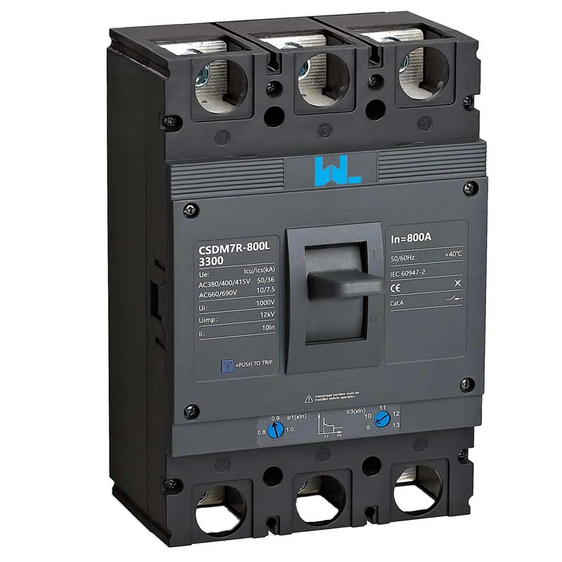
Application decisions across diverse settings
The same thermal MCCB cannot be transferred between applications without checking duty, environment and system topology. Use these scenarios as a design prompt rather than a universal setting.
- Commercial HVAC and pumps: Record motor full-load current, locked-rotor current and starts per hour. Coordinate the MCCB with the motor overload relay and starter; verify that a permitted start does not cross the magnetic pickup.
- Manufacturing lines: Conveyor drives and welders create intermittent peaks. Check diversity assumptions, harmonic heating and short-circuit current at each panel. Lock and document any adjustable thermal or magnetic settings.
- Transformer secondaries: Transformer inrush is short-lived and asymmetric. Use the transformer impedance and manufacturer’s inrush data to choose a curve, then calculate secondary fault current before selecting Icu or the UL interrupting rating.
- Photovoltaic and battery distribution: DC arcs and bidirectional current require breakers specifically rated for the circuit’s DC voltage, polarity and isolation duty. The MCCB guide for photovoltaic distribution lines explains why AC ratings cannot simply be reused on a DC feeder.
- Data centers and healthcare facilities: Availability and selective coordination are critical. Use tested time delays, status contacts and maintenance procedures; confirm that bypasses and alternate sources do not exceed the marked fault duty.
For every setting, verify neutral treatment, poles, enclosure ingress protection and the disconnecting method required by the destination code.
Compare thermal MCCB configurations before procurement
A scan-friendly comparison helps a project team price the whole protection function rather than only the breaker body.
| Decision dimension | Fixed thermal-magnetic MCCB | Adjustable thermal-magnetic or electronic MCCB | 조달의 의미 |
|---|---|---|---|
| Overload setting | Factory-set thermal response | Trip range may be adjustable; electronic units add long-time delay | Match conductor ampacity and expected load profile |
| Short-circuit response | Magnetic instantaneous element | Magnetic pickup or short-time delay varies by series | Request curves and verify selectivity with upstream devices |
| Environment | Simple, fewer electronics | More functions but greater setup and testing responsibility | Check ambient derating, vibration and enclosure heat |
| Accessories | Auxiliary, alarm and shunt options vary | May add communications, metering and test interfaces | Reserve panel space and control power; confirm availability |
| Lifecycle cost | Lower complexity; easy like-for-like replacement | More engineering and commissioning, potentially fewer nuisance outages | Include studies, testing, spares and downtime in TCO |
Application-to-rating map
| Setting | Primary risk | Data to verify | Typical evidence pack |
|---|---|---|---|
| 모터 피더 | Starting current and overload | Full-load and locked-rotor current | Motor data sheet, overload settings, time-current plot |
| Transformer secondary | Inrush and available fault current | Impedance, inrush and secondary fault level | Transformer schedule and coordination study |
| PV/DC combiner | DC arc and reverse contribution | DC voltage, polarity and isolation duty | Array/inverter data and DC-rated breaker declaration |
| Critical facility panel | Loss of selectivity or unsafe maintenance | Source modes, short-circuit level and delay settings | Single-line diagram, test record and labeling |
Sizing, coordination and total-cost checks
Illustrative calculation (not a design value): A balanced 45 kW, 400 V, three-phase pump at power factor 0.86 and efficiency 0.91 has running current I ≈ 45,000/(√3 × 400 × 0.86 × 0.91) ≈ 83 A. A designer might investigate a 125 A frame with a 100 A trip, then verify cable ampacity, starting current, ambient derating and the starter’s overload range. The calculation estimates running current only; it does not establish breaker size.
Selective coordination means the device nearest a fault opens first while upstream equipment remains energised. Plot the thermal MCCB and upstream curves at the actual voltage, then check let-through energy, short-time withstand and any series-combination rules. If a study finds 30 kA prospective current at a panel, a 25 kA IEC service declaration or lower marked interrupting rating is inadequate.
Total cost of ownership includes engineering, commissioning, calibrated trip testing, spares, thermal scans and avoidable outage risk. A fixed device may suit a stable feeder; a configurable unit can pay back when loads change, provided settings are controlled and retested.
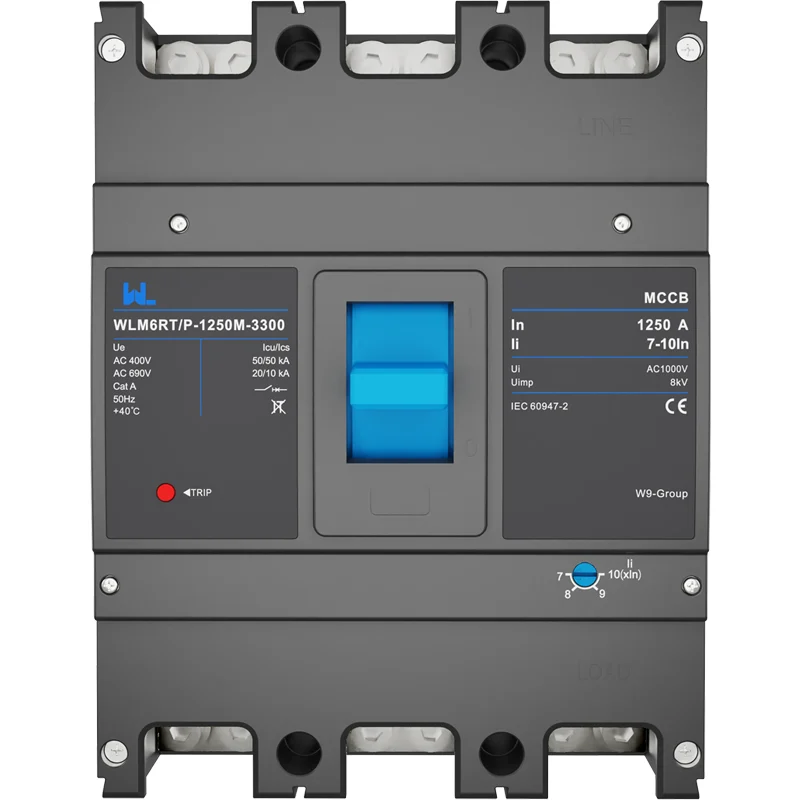
Standards, installation and maintenance evidence
IEC 60947-2 covers low-voltage circuit-breaker construction, performance and verification, including declarations such as Icu 그리고 Ics. UL 489 is the North American safety standard for molded-case circuit breakers and enclosures; its markings and test framework are not interchangeable with IEC declarations. NFPA 70 (NEC) is a US installation code covering conductors, overcurrent protection, disconnects and working space—it is not a product certification. IEC 60364 or a local wiring code may govern projects elsewhere.
State the destination market, panel listing route and intended use in the purchase specification. During installation, verify lug compatibility, conductor preparation, torque, phase identification, creepage and clearance. Before handover, exercise the mechanism, test trip functions with calibrated equipment and retain the manufacturer’s instructions, curves and settings sheet. Inspection frequency depends on duty and environment; follow the series instructions and the site risk assessment.
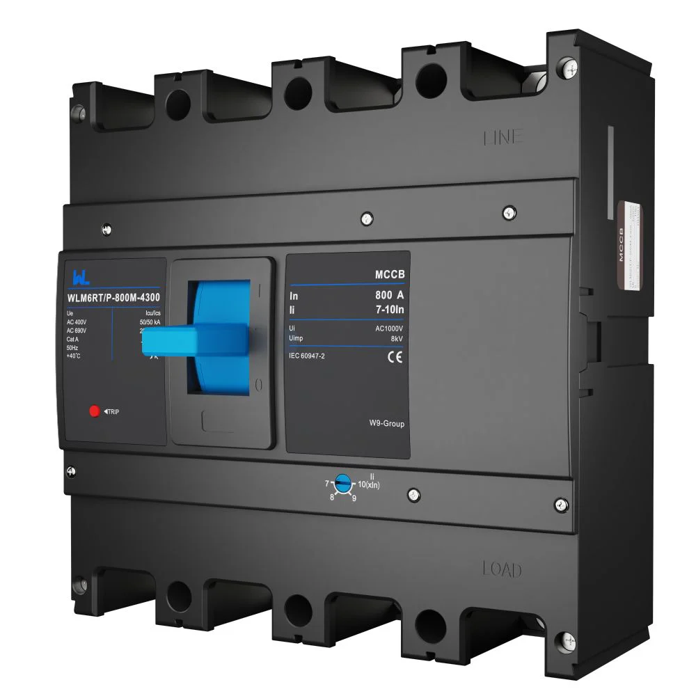
Thermal MCCB selection checklist
- Record system voltage, frequency, earthing, continuous load, inrush, ambient temperature and enclosure conditions.
- Calculate prospective short-circuit current at the installation point; specify IEC Icu/Ics or the applicable UL 489 marking.
- Choose frame, trip current, poles, neutral protection, AC/DC duty and terminal accessories; confirm dimensions and replacement parts.
- Complete coordination and arc-energy reviews; document final thermal and magnetic settings and protect them from unauthorised changes.
- Plan commissioning, periodic inspection, spare strategy and end-of-life replacement. Include curves, torque data, labels and test records in the handover pack.
Zhejiang W9 Group Technology Co., Ltd. supplies low-voltage protection products and supports OEM/ODM configuration, testing coordination and documentation. Buyers should provide the duty, standards and panel constraints above so a proposed thermal MCCB can be evaluated on evidence. For related guidance, see the thermal-magnetic circuit-breaker selection tips and our 조정 가능한 MCCB 개요.
자주 묻는 질문
What is a thermal MCCB?
A thermal MCCB is a molded case circuit breaker with a heat-responsive overload element and a magnetic short-circuit element. It protects feeders and equipment when its ratings and trip curve match the installation. Confirm the product’s voltage, poles and interrupting declaration before use.
Can a thermal MCCB protect a motor?
Yes, when coordinated with the motor starter and overload relay. Check full-load and locked-rotor current, starts per hour and the magnetic pickup so normal inrush does not trip. Follow the motor manufacturer’s and local code requirements for overload and disconnect protection.
How do I choose the correct thermal MCCB rating?
Start with continuous load and conductor ampacity, then check voltage, poles, ambient derating and prospective short-circuit current. Select an IEC Icu/Ics or UL interrupting rating that meets the calculated fault duty. A qualified designer should verify coordination and installation conditions.
Are IEC Icu and a UL interrupting rating equivalent?
No. They belong to different standards and test frameworks, and values must not be converted casually. Specify the destination market and use the marked declaration accepted by the authority having jurisdiction.
What maintenance does a thermal MCCB require?
Follow the product instructions for visual inspection, mechanism operation, torque checks, thermal scanning and functional trip testing with calibrated equipment. Frequency depends on duty, environment and risk. De-energise safely, document results and replace a breaker that has interrupted a fault when the manufacturer requires it.
Authoritative references
- 국제 전기기술위원회(IEC), IEC 60947-2, Low-voltage switchgear and controlgear — Circuit-breakers.
- UL Solutions, UL 489, Molded-Case Circuit Breakers and Circuit-Breaker Enclosures.
- National Fire Protection Association, NFPA 70, National Electrical Code.
- NEMA standards, guidance for low-voltage circuit-breaker application and ratings.
The safest thermal MCCB is the one whose curve, fault duty and maintenance record fit the system—not simply the largest ampere number. Share your load schedule, fault study and destination standard with our team, then review documented products and protection options on the W9 products page.