






























Photovoltaic 800V Molded Case Circuit Breaker for Solar Protection
Photovoltaic 800V Molded Case Circuit Breaker for Solar Protection
When Elena Martín, an EPC electrical engineer in Seville, Spain, energised a rooftop array, the combiner breaker opened within seconds and a blue flash appeared at a cable lug. Replacing the breaker did not help. Investigation found a selection and process problem: the device came from an AC schedule, polarity markings were not followed, and a retrofit gland reduced enclosure spacing. An 800V photovoltaic MCCB specified for DC duty, installed with intended spacing and coordinated with inverter protection, stopped the trips. In a high-voltage PV field, solar MCCB protection depends on the complete circuit—not the label alone.
요약: An 800V photovoltaic MCCB is a DC protection element for PV strings, combiner outputs or inverter feeders; it must be selected against the array’s maximum open-circuit voltage, fault current, polarity and interruption duty. IEC 60947-2 covers circuit-breaker performance, while IEC 62548 addresses PV array design. A breaker marked for 690V AC is not automatically suitable for 800V DC. Confirm the manufacturer’s DC test data, pole wiring, thermal derating and coordination study before ordering. In practice, solar MCCB protection works best as a layered plan with string fuses, a correctly rated surge protective device (SPD), a lockable isolator and a documented maintenance procedure.
Why 800V-class PV distribution needs a DC-specific approach
Modern utility and commercial arrays place more modules in series to reduce cable current and copper losses. A “class” voltage describes the design envelope; the actual worst case is the cold-temperature open-circuit voltage (Voc) multiplied by the number of series modules, plus tolerances. Designers should calculate that value at the site’s minimum temperature, then compare it with the breaker’s verified DC operating voltage. An 800V photovoltaic MCCB should therefore be treated as a system component, not a generic frame size.
From string to inverter
At the string level, module leads feed a combiner box, where parallel currents are collected and monitored. A main DC disconnect or feeder breaker then supplies the inverter. The breaker’s continuous current setting should protect the conductors without opening during expected irradiance peaks, while its short-circuit capacity must exceed the prospective PV fault current and any contribution from the inverter’s DC link. A molded case circuit breaker used at each boundary must have pole and terminal arrangements that match the current path.
Use the supplied wiring diagram. Some DC breakers require poles in series to lengthen the arc path; others have a defined line/load orientation. Reversing polarity or omitting a pole link can defeat the magnetic trip path, so record the installed polarity in the as-built drawing.
Interrupting a DC arc
Unlike AC, PV DC current has no natural current zero every half cycle. When contacts separate, an arc can persist until the breaker creates enough voltage drop and magnetic force to stretch and cool it. That is why solar MCCB protection relies on a DC-rated chamber, arc runners and a tested pole configuration. IEC 60947-2 short-circuit tests use defined time constants and prospective currents; request the test category and voltage for the exact pole arrangement rather than accepting an AC interrupting number.

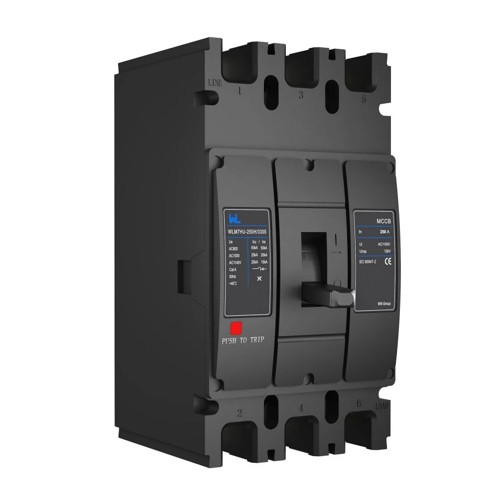
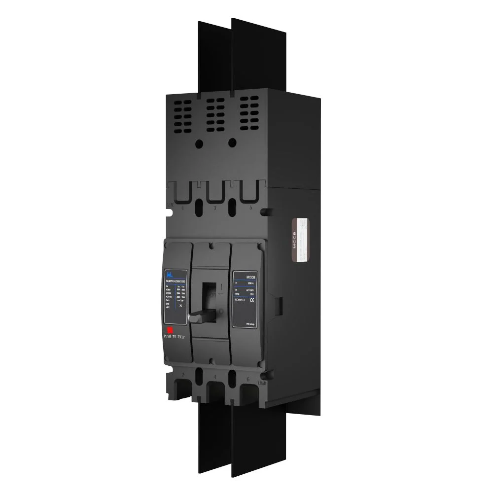
Design details that make solar MCCB protection dependable
Polarity, creepage and clearance
DC polarity is not a marking detail. Route positive and negative conductors as shown by the manufacturer, keep touch-safe barriers in place and label both ends. Creepage is the surface distance across insulation; clearance is the through-air distance. Dust, humidity and salt reduce insulation performance, so IEC 60947-1 insulation coordination and the enclosure’s pollution-degree assumptions matter. Do not drill a gland or add a busbar shield that cuts the specified spacing.
For an 800V photovoltaic MCCB, compare rated insulation voltage (Ui), impulse withstand (Uimp) and working DC voltage with the array calculation. A higher Ui does not prove 800V DC interruption. Request the installation drawing, tightening torque and arc-exhaust spacing.
Thermal derating and enclosure heat
Trip units sense temperature as well as current. Roof boxes can exceed the 40°C reference used by many datasheets; grouping and cable heating add load. Apply the ambient correction, then verify conductor ampacity at the adjusted setting. Illustrative check: a 250A frame with a 0.8 correction supports 200A (250 × 0.8), unless the trip-unit data says otherwise. This is not a product rating.
Selectivity with fuses, inverters and SPDs
Selective coordination keeps a string fault from shutting down an entire block. Compare time-current curves for string fuses, the combiner breaker and inverter protection. Settings too low can trip on inrush; settings too high can expose cables. Document the discrimination limit at study current and temperature.
An SPD limits transient overvoltage; it does not replace overcurrent protection or a service disconnect. IEC 61643-31 addresses PV DC SPDs. Provide backup protection, short-circuit rating and lead length, and place the SPD near protected equipment. A lockable isolator supports maintenance, but only a breaker with verified DC interrupting capability should clear a fault. Together these layers support PV system safety.
Application comparison for an 800V photovoltaic MCCB
| Location | Primary duty | Checks before approval | Typical coordination partner |
|---|---|---|---|
| String/combiner input | Protect conductors and isolate a string group | Cold Voc, fuse rating, polarity, spacing | gPV fuses and DC SPD |
| Combiner output | Clear parallel-string faults and isolate locally | Summed Isc, ampacity, DC test, derating | String fuses and inverter protection |
| Inverter feeder | Protect the larger DC feeder and permit service isolation | Inverter DC input limits, prospective fault current, selectivity study | Inverter disconnect, SPD and upstream switchgear |
Application choices and total-cost effects
| Decision dimension | Option A | Option B | Cost or risk implication |
|---|---|---|---|
| Trip unit | Fixed thermal-magnetic | Adjustable or electronic (when documented) | Adjustability can improve coordination; verify settings access and test method. |
| Poles | Dedicated two-pole DC path | Three/four-pole arrangement per wiring diagram | Series poles may raise interrupting capability only when tested that way; extra poles add space and terminations. |
| Mounting | Indoor combiner enclosure | Outdoor roof or field cabinet | Outdoor heat, UV, dust and moisture can increase derating and inspection work. |
| 보수 | Visual and torque checks | Scheduled insulation and functional tests | More planned labor can reduce downtime and reveal loose lugs before arcing. |
Standards, listings and market compliance
Use the standard that matches the product function and destination market:
- IEC 60947-2 specifies circuit-breaker characteristics and short-circuit verification; it is not a blanket certification claim.
- IEC 60947-1 provides general rules for terminals, insulation, temperature rise and marking.
- IEC 62548 gives PV array design and installation practices, including protection and switching.
- IEC 61643-31 covers PV DC SPDs; coordinate the SPD with backup protection.
- UL 489 covers molded-case circuit breakers, while UL 98 primarily covers enclosed switches; listings are not interchangeable.
- NFPA 70 (NEC) Articles 690 and 705 address PV and interconnected sources in the United States; local adoption controls.
Ask for a declaration, listing or test report naming voltage, current, poles and accessories. Unsupported “UL,” “IEC certified” or 800V claims can trigger inspection and warranty problems.
Selection checklist for procurement teams
- Calculate maximum Voc and Isc using the site’s temperature range, module data and parallel strings; record assumptions.
- Match the breaker’s verified DC working voltage, interrupting test, polarity and pole wiring to that calculation.
- Apply ambient, enclosure and grouping derating; check conductor ampacity, lug range and tightening torque.
- Run a time-current coordination review with fuses, inverter protection and SPD backup protection.
- Approve drawings, labels, spare parts and a lockout/inspection schedule before shipment.
Zhejiang W9 Group Technology Co., Ltd., founded in 2020, supplies low-voltage protection products and can discuss OEM/ODM configurations, documentation and testing support. Request exact DC evidence rather than assuming a catalogue family covers every 800V photovoltaic MCCB application. See the molded case circuit breaker reference and confirm suitability with its current datasheet.
자주 묻는 질문
Can an AC MCCB be used on an 800V PV string?
Not by voltage label alone. DC arc behavior, polarity and pole wiring require a molded case circuit breaker tested for the intended DC voltage and fault current. Obtain the manufacturer’s DC data and wiring diagram before approval.
Where should a photovoltaic MCCB be installed in a PV system?
It may protect a combiner output, inverter feeder or another defined boundary, provided its ratings match that location. String-level protection may still require gPV fuses. Map every device on the single-line diagram and verify isolation access.
How does solar MCCB protection differ from an SPD?
A breaker clears sustained overcurrent and short circuits; an SPD diverts transient overvoltage. The SPD needs coordinated backup protection and short leads. Using one in place of the other leaves a gap in PV system safety.
Why do creepage and clearance matter more outdoors?
Moisture, dust and salt can create surface leakage and reduce insulation margin. Follow the product’s pollution-degree assumptions, spacing drawings and enclosure rating. Recheck spacing after adding glands, shields or monitoring hardware.
What maintenance should an 800V photovoltaic MCCB receive?
Follow the manufacturer’s interval for visual inspection, torque verification, insulation checks and functional tripping. De-energise, lock out and prove absence of voltage before work. Record heat discoloration, corrosion, nuisance trips and any replaced accessories.
참고문헌
- IEC, IEC 60947-1 and IEC 60947-2, Low-voltage switchgear and controlgear, https://www.iec.ch/.
- IEC, IEC 62548, Photovoltaic arrays—Design requirements, https://www.iec.ch/.
- IEC, IEC 61643-31, Surge protective devices connected to photovoltaic systems, https://www.iec.ch/.
- NFPA, NFPA 70 National Electrical Code, Articles 690 and 705, https://www.nfpa.org/.
- UL Standards & Engagement, UL 489 and UL 98, https://www.shopulstandards.com/.
Reliable PV system safety is designed in the wiring diagram, verified in the test record and preserved by disciplined maintenance. Select the 800V photovoltaic MCCB only after those three documents agree.
For a project-specific review, compare your single-line diagram and duty schedule with W9’s low-voltage protection team, then read the MCCB distribution guide 그리고 PV protection overview. Browse available configurations at W9 products and contact the team for drawings, testing scope and OEM/ODM discussion.