































125 Amp Circuit Breaker: Reliable Overload and Short-Circuit Protection
125 Amp Circuit Breaker: Reliable Overload and Short-Circuit Protection
When Elena, a maintenance supervisor in Rotterdam, energized a new 125 amp feeder for a packaging line, the breaker opened before the first carton moved. A replacement with the same nameplate tripped again during motor starting, and a larger fuse upstream threatened to leave the cable unprotected. A review of the load schedule, conductor temperature and prospective fault current reversed the diagnosis: the device was not simply “bad”; the 125 amp circuit breaker had been selected without checking continuous load, inrush, interrupting capacity and coordination.
요약: A 125 amp circuit breaker is a current rating, not a complete protection specification. The selected device must protect the conductor against overload, interrupt the calculated prospective fault current and provide the poles, voltage, trip curve and isolation required by the installation. Under IEC 60947-2, low-voltage circuit-breaker characteristics are verified by declared tests; UL 489 covers molded-case breakers in its North American conformity system, while NFPA 70 provides installation rules in applicable U.S. jurisdictions. Start with a load and fault study, compare the result with the cable and device ratings, then document settings and commissioning tests. Do not assume that every 125 A device, or every residual-current device marked 125 A, includes overcurrent protection.
What the 125 amp rating tells—and does not tell—you
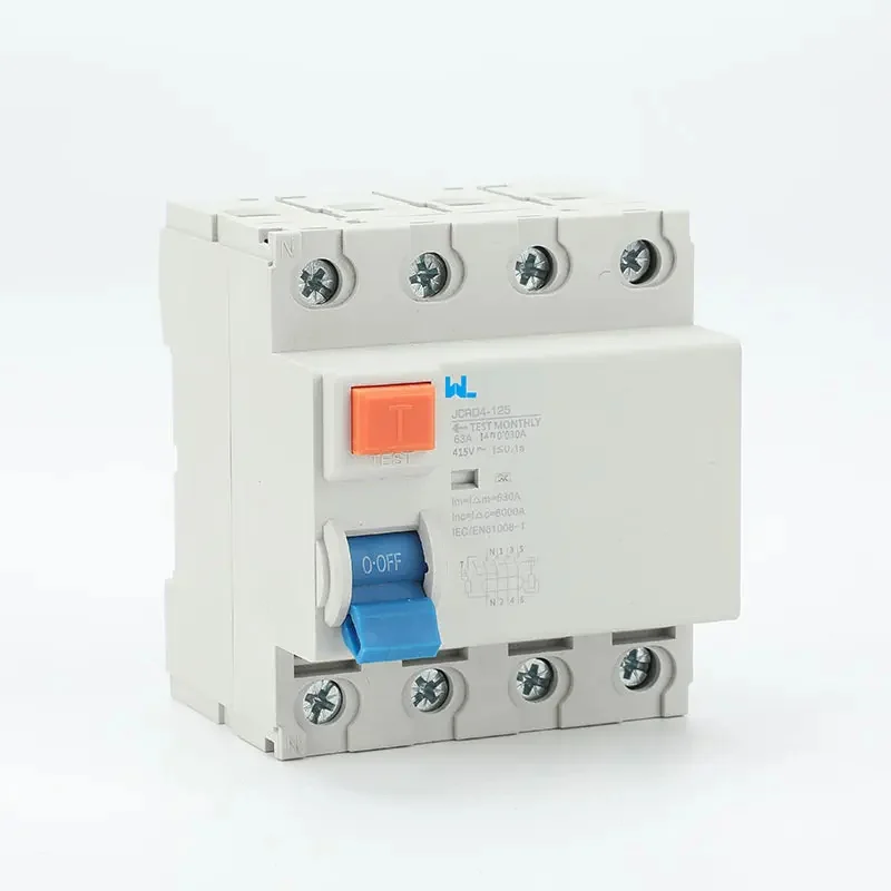
The number 125 A normally identifies the device’s rated current (In), the continuous current it can carry under stated reference conditions. It does not identify voltage, number of poles, short-circuit breaking capacity, trip curve or residual-current sensitivity. A 125 A thermal-magnetic MCCB may protect overload and short circuit; a 125 A RCCB may provide earth-leakage protection only and rely on an upstream MCB or fuse for overcurrent. Read the complete marking and datasheet before comparing products.
Conductor protection is the first coordination check. In IEC installations, the design current (Ib) should not exceed the protective-device rating (In), and In should not exceed the conductor’s permissible current (Iz) after installation and ambient corrections. In U.S. work, continuous loads are commonly sized at 125% under NEC rules; the authority having jurisdiction and the exact article determine applicability. A 125 A breaker therefore does not automatically justify a 125 A cable: grouping, enclosure temperature, conductor insulation and voltage drop can reduce ampacity.
Overload, short circuit and residual current are different events
Thermal protection responds to sustained overcurrent and allows for normal, short-duration variation. Magnetic or instantaneous protection responds to a high-magnitude short circuit in milliseconds, subject to the device’s time-current curve. Residual-current protection compares currents in the live conductors and trips when leakage exceeds its declared IΔn. These functions can coexist in an RCBO or electronic MCCB, but their ratings and test methods remain distinct.
Breaking capacity and coordination at 125 A
Interrupting capacity is expressed in kiloamps (kA) and must be greater than the prospective short-circuit current (PFC) at the installation point. A 6 kA marking, for example, is not a promise to interrupt a 10 kA fault. Calculate PFC from transformer impedance, source contribution, conductor length and upstream equipment; then select a device whose tested rating and backup-protection conditions cover the result. IEC 60947-2 and UL 489 use different conformity frameworks, so specify the one required by the destination market.
Coordination asks which protective device clears a fault first. For a motor or transformer feeder, expected inrush can overlap a fixed magnetic pickup. Time-current curves show whether a downstream breaker clears before the upstream 125 A device, preserving healthy loads. Adjustable trip units may offer long-time, short-time, instantaneous and ground-fault settings, but every setting must stay within the manufacturer’s range and the equipment withstand time. Record the final values on the panel schedule.
| Specification item | Question for the 125 A breaker | Evidence to retain |
|---|---|---|
| Rated current (In) | Does 125 A coordinate with Ib, Iz, continuous-load rules and derating? | Load calculation, conductor ampacity worksheet and nameplate. |
| Voltage and poles | Does the device match system voltage, phase arrangement and neutral-isolation needs? | One-line diagram, pole configuration and wiring diagram. |
| Breaking capacity | Is the tested interrupting rating above calculated PFC at the mounting point? | IEC 60947-2 or UL 489 declaration and fault study. |
| Trip characteristic | Will thermal, magnetic or electronic settings tolerate inrush yet clear faults? | Manufacturer time-current curve and approved setting sheet. |
| Residual-current function | Is leakage protection integrated, separate or not required? | RCBO/RCCB type, IΔn, test instructions and coordination record. |
Choosing the right 125 amp circuit breaker format
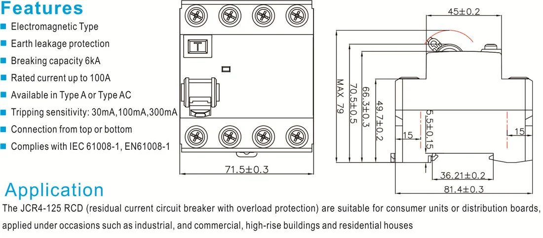
For a three-phase feeder, a three-pole MCCB interrupts the phases; a four-pole version also switches the neutral where the design requires simultaneous isolation. A single-pole or two-pole device may suit a different system, but pole count must follow the earthing arrangement and local wiring rules. A breaker’s enclosure rating and terminal clearances also matter in dusty, damp or high-temperature panels.
| Option | Protection scope | Typical fit | Procurement caution |
|---|---|---|---|
| 125 A thermal-magnetic MCCB | Overload plus short-circuit interruption | Feeders, small machinery and distribution boards | Check Icu/Ics, poles, curve, voltage and cable coordination. |
| 125 A adjustable electronic MCCB | Overload, short circuit and optional ground-fault functions | Motors, generators and changing industrial loads | Requires a study, locked settings and possible injection testing. |
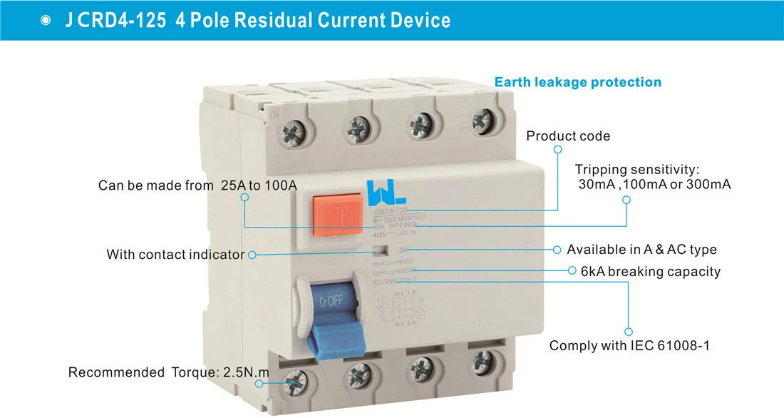
| 125 A RCCB plus upstream MCB/fuse | Residual-current protection; overcurrent supplied separately | Installations requiring earth-leakage protection | Do not market the RCCB alone as overload protection. |
| 125 A RCBO | Integrated residual-current and overcurrent protection | Where selective leakage and overcurrent protection are needed in one device | Verify device type, sensitivity, short-circuit rating and neutral arrangement. |
The total cost of ownership includes engineering, panel space, testing, spare strategy and outage exposure—not just the purchase price. An adjustable unit can avoid a hardware change when a documented load increases, while a fixed device may be simpler and less costly for a stable feeder. Compare both options against maintenance capability and the consequence of a nuisance trip. Our guide to choosing a moulded-case circuit breaker provides a related decision framework.
Standards, testing and installation records
IEC 60947-2 is the principal product standard for many industrial low-voltage circuit breakers. IEC 60364-4-43 addresses protection against overcurrent in installations, while IEC 60364-5-53 covers selection and erection of switching and control devices. UL 489 covers molded-case circuit breakers and related enclosures in its certification system; NFPA 70 sets installation requirements for covered U.S. work. These documents have different scopes: a product test report is not an installation permit, and a wiring code does not prove a device’s interrupting test.
Commissioning should include visual inspection, conductor identification, protective-conductor continuity, insulation resistance where appropriate, polarity, torque verification and functional operation. For an electronic trip unit, follow the manual for primary- or secondary-injection testing; for an RCBO or RCCB, use a tester compatible with the device type and measure residual-trip performance. Record the circuit tag, measured values, instrument identity and date. Re-test after a major modification or a setting change.
Five actions before ordering a 125 A breaker
- Calculate Ib, continuous-load demand, Iz after derating, voltage drop and motor or transformer inrush.
- Calculate PFC at the installation point and select a tested interrupting rating with any required backup combination.
- Define poles, system voltage, frequency, trip curve, residual-current type and environmental enclosure conditions.
- Run time-current coordination with upstream and downstream devices; document adjustable settings and arc-flash inputs where required.
- Request the exact datasheet, drawings, declarations, accessory list and commissioning procedure, then retain the as-left record.
For terminology and product families, review the site’s circuit-protection products range and the guide to MCB roles in electrical safety. A supplier can help compare frame sizes and accessories, but the project engineer or licensed electrician remains responsible for final ratings and settings.
자주 묻는 질문
What is a 125 amp circuit breaker used for?
It is commonly used to protect a feeder, distribution board or equipment branch designed for up to 125 A under stated conditions. The actual application depends on conductor ampacity, voltage, poles, load profile and fault level. A 125 A marking alone does not identify the protection functions.
Can a 125 A breaker carry 125 A continuously?
Only when the device and installation are rated for that duty and the conductor remains within its permissible temperature. Continuous-load rules, ambient temperature and grouping may require derating or a larger frame. Verify the product data and the applicable wiring code.
Is a 125 A RCCB the same as a 125 A circuit breaker?
No. An RCCB detects residual current and normally needs a separate overcurrent device. An RCBO combines residual-current and overcurrent functions; an MCCB generally provides overcurrent protection but not every leakage or arc-fault function.
How many kA should a 125 A breaker be?
Choose a tested breaking capacity that exceeds the calculated prospective fault current at the installation point. The correct value could be 6 kA, 10 kA or higher depending on the supply and device family. Never select kA from the current rating alone.
What testing is required after installation?
Use the applicable commissioning plan: inspect and torque terminals, verify continuity, insulation and polarity, and operate the breaker. Where fitted, test electronic trip functions or residual-current operation with compatible calibrated equipment, then record results and settings.
참고문헌
- IEC 60947-2, Low-voltage switchgear and controlgear—Circuit-breakers.
- IEC 60364-4-43, Protection against overcurrent.
- UL 489, Molded-Case Circuit Breakers and related enclosures.
- NFPA 70, National Electrical Code.
The reliable 125 A installation is the one whose cable, fault level, trip curve and test record agree—not merely the one with “125 A” printed on its face.
When you are ready to compare models, explore the circuit-protection range 그리고 contact the W9 team with your one-line diagram, load schedule and destination-market requirements.