


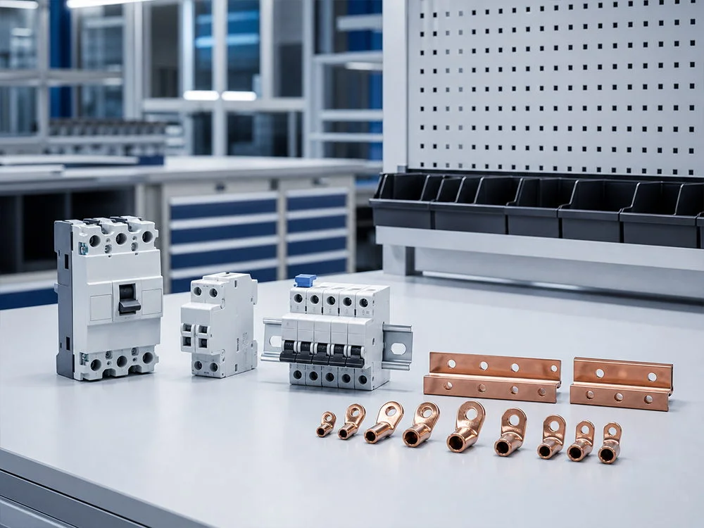

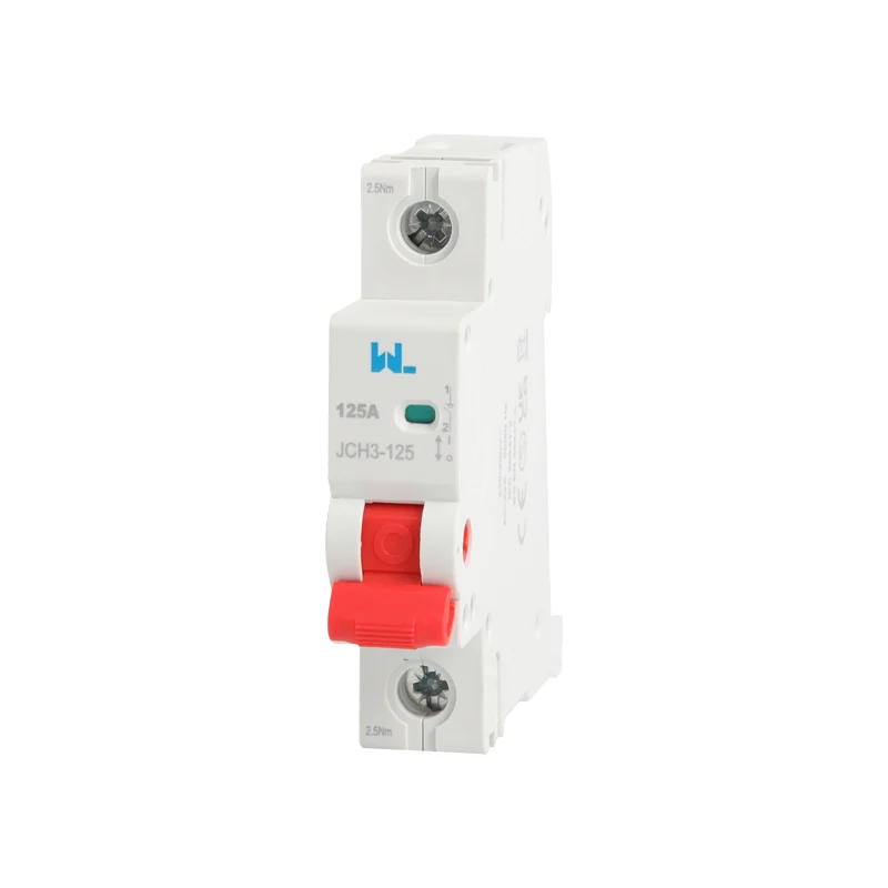
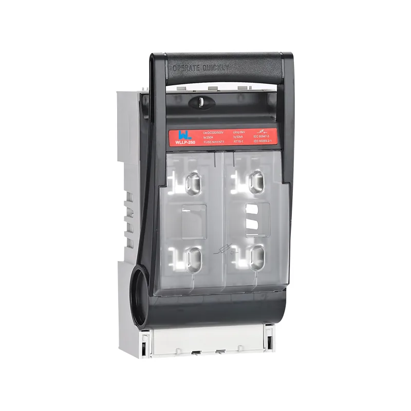
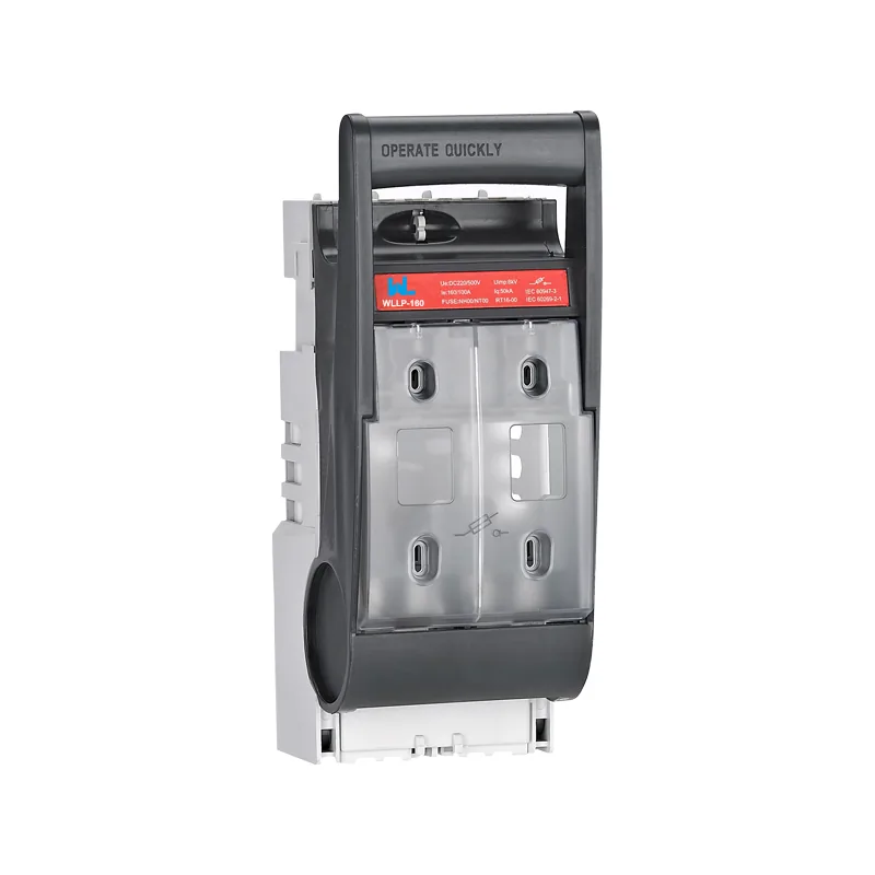





トリプル・トゥーリズム・プロテクター:RCBOが現代の回路をどのように守るか
A branch circuit can trip while its load current remains below the RCBO’s ampere rating. Overcurrent, residual-current imbalance and wiring errors are different diagnostic paths. Circuit-level protection helps locate the affected zone, but identifying the trip function is the first step toward a defensible repair.
Summary: An RCBO puts overcurrent protection and residual-current protection in the same circuit-level device, so one branch can be isolated without needlessly removing power elsewhere. Under IEC 61009-1, an RCBO is a residual-current circuit-breaker with integral overcurrent protection; IEC 60364 then guides how it is selected and installed. Map each circuit’s load, fault level, neutral arrangement and required IΔn before choosing a pole configuration, then verify the finished installation with the tests required by local rules.
Modern buildings add electronic loads, outdoor equipment and power-conversion stages. Leakage can be normal, while a loose termination or insulation fault can become dangerous. RCBO protection contains events at the point where they occur when device and wiring are coordinated. Proper RCBO protection assigns residual current protection to the responsible branch.
RCBO Protection Functions
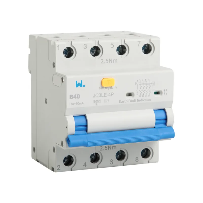
An RCBO combines three responses that are often specified separately:
- Overload protection responds to sustained excess current according to the declared trip curve. Many common RCBOs use a thermal release; verify the exact construction and reference conditions.
- Short-circuit protection interrupts high fault current within the rated capacity and operating characteristics. Common designs use a magnetic release; the product’s declared performance governs selection.
- Residual-current protection: a core-balance sensor compares currents leaving and returning through the intended conductors. An imbalance indicates current flowing elsewhere, such as through protective earth or a person, and initiates disconnection at the selected sensitivity.
This integration is the practical difference between RCBO protection and a residual-current device that needs a separate breaker. It also means the manufacturer’s curves, terminal limits and wiring instructions must be treated as one system. Do not assume that combining functions increases interrupting capacity or solves upstream selectivity.
Illustrative load check
Suppose a single-phase branch is designed for 16 A at 230 V. Its notional maximum apparent power is 16 × 230 = 3.68 kVA. If a measured design demand is 2.4 kW, the continuous current at unity power factor is about 2,400 ÷ 230 = 10.4 A, leaving margin for starting current and temperature derating. This is an illustrative calculation, not a prescription: the installer still checks cable capacity, installation method, prospective short-circuit current, voltage drop and the RCBO’s declared characteristics.
RCBO vs RCCB Circuit Selectivity
With one upstream RCCB feeding many MCBs, a small earth-leakage event can open the common RCCB and interrupt every downstream circuit. Individual RCBO protection moves the residual-current decision to each branch. A fault on an EV charger can then disconnect the charger while refrigeration, access control and emergency lighting remain energized—subject to the distribution design and local requirements.
True selectivity is not guaranteed merely because devices have different ampere ratings. Compare residual-current operating characteristics, short-circuit energy limits and manufacturer coordination tables. Time-delayed upstream devices, where permitted, may help discrimination, but only a documented study using the actual combinations is defensible. This is a central RCBO vs RCCB design distinction: the RCBO offers finer fault localization, while an RCCB-plus-MCB arrangement may suit an intentional common trip or tighter budget.
For example, an upstream RCCB feeding eight branches can disconnect all eight when one branch leaks; eight branch RCBOs localize the expected trip to one branch, subject to coordination.
| 寸法 | RCBO on each branch | One RCCB with branch MCBs |
|---|---|---|
| Fault localization | Trips the affected circuit; easier diagnosis. | Common trip can remove several circuits. |
| Panel space | More modules or compact two-in-one devices, depending on design. | Fewer residual-current devices, plus separate MCBs. |
| Neutral management | Neutral is routed with the protected branch as specified. | All downstream neutrals must remain on the correct RCCB side. |
| Coordination work | Check branch and upstream curves for selectivity. | Check RCCB immunity, MCB curves and shared leakage. |
| Maintenance impact | One branch can be isolated for testing or service. | Testing may affect a larger group. |
| Unit-cost tendency | Higher device count cost, often offset by reduced downtime. | Lower device count cost, with possible outage and troubleshooting cost. |
Localize the Trip Before Replacing Devices
Record which device opened, its trip indicator where provided, the connected loads and the operating sequence. Distinguish a branch RCBO trip from operation of a shared upstream RCD. A branch fault can still disconnect an upstream device if the residual-current or short-circuit combination is not selective. The RCBO安全ガイド explains why smaller protective zones help continuity, but zone size alone does not prove discrimination.
A useful trip record includes time, load state, recent wiring changes, leakage measurement and device test mode. If the cause is uncertain, a competent person should investigate both the load and wiring before replacing the breaker or increasing sensitivity. Do not repeatedly re-energize a circuit showing heat damage, burning smells or a persistent fault.
RCBO Requirements for Electronic Loads
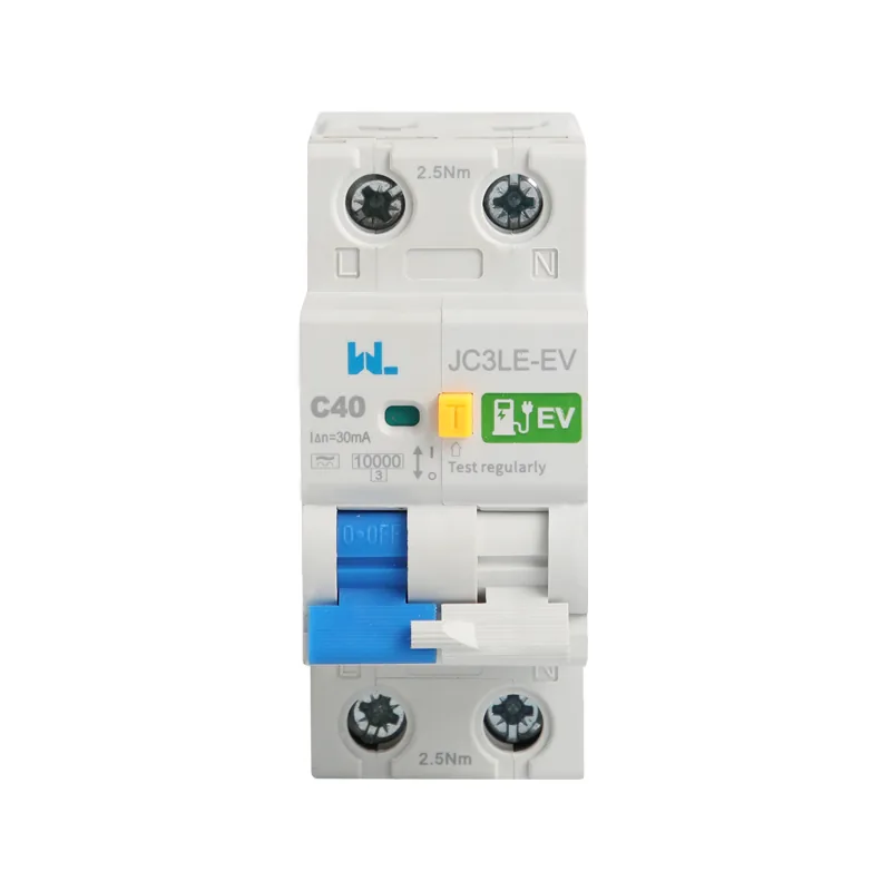
The current-sensing path must include every live conductor that belongs to the circuit; a neutral borrowed from another circuit can create nuisance tripping or defeat residual-current protection. Follow the wiring diagram for line-neutral devices and for two-, three- or four-pole arrangements. A switched neutral, a solid neutral and a neutral pole that opens with the phases each have different consequences for isolation and maintenance.
In a three-phase, four-wire feeder, a four-pole device monitors the phases and neutral together. In a single-phase circuit, a two-pole RCBO commonly switches line and neutral, but the arrangement depends on the earthing system and national rules. Verify terminal markings, torque and conductor preparation; these details are part of overcurrent protection performance.
Variable-speed drives, LED drivers, heat pumps and EV chargers can produce smooth DC or high-frequency leakage. Select the residual-current type and immunity specified by the equipment maker and installation standard. An RCBO sensitive to the wrong waveform can nuisance-trip—or fail to provide the intended residual current protection.
Keep the Neutral with Its Circuit
A shared neutral can carry normal load current outside the RCBO’s monitored return path, producing residual imbalance without an overload. Confirm the line and corresponding neutral against the as-built diagram, including connections through changeover equipment or other supply sources. A no-load test can miss a fault that appears only when another circuit is energized; controlled investigation must follow safe isolation and approved testing procedures.
The guide to RCBOがする仕事 explains the combined functions and helps separate a residual-current trip from an overcurrent event.
For charging loads, consult RCBO selection for EV chargers and verify both DC residual-current detection and the required AC residual protection. These checks concern waveform compatibility and current paths, so the nominal ampere rating cannot settle them.
Scope of Applicable Standards
IEC 61009-1 sets product requirements for residual-current circuit-breakers with integral overcurrent protection (RCBOs) for household and similar uses. It addresses construction, operating characteristics and verification tests; it is not blanket installation approval.
IEC 60364 is the low-voltage installation framework. Its national adoptions address residual current protection, shock, overcurrent, isolation, verification and special locations. Apply the locally adopted edition, including rules for EV charging, bathrooms or medical areas where relevant.
IEC 60947-2 covers circuit-breakers for industrial and similar applications. It is broader in many commercial settings than the household-focused IEC 61009-1 scope; do not market an IEC 61009-1 device as an IEC 60947-2 breaker without evidence that it is designed and tested to that standard.
In North America, UL 943 addresses ground-fault circuit-interrupters (GFCIs), while UL 489 covers molded-case circuit breakers and enclosures. They are distinct scopes. Do not transfer a claim between them without applicable listing and evaluation. Match destination market, voltage, marking and inspection authority.
RCBO Application Guide
| 申請 | 主な懸念事項 | Design action |
|---|---|---|
| Domestic sockets and wet rooms | Human contact and cumulative leakage. | Use the locally required residual-current sensitivity; keep neutrals segregated and test at commissioning. |
| EV charging point | DC components and outdoor exposure. | Follow charger instructions for residual-current type, earthing and upstream coordination. |
| Commercial refrigeration or HVAC | Continuity and motor starting current. | Review inrush, ambient derating and selectivity so one fault does not stop unrelated loads. |
| Data, controls and fire systems | Unwanted interruption has operational consequences | Review any special circuit requirements, permitted protective arrangement, leakage and shutdown procedures with the designer; do not introduce a bypass as a generic remedy |
| OEM機械パネル | Repeatable production wiring and compliance evidence. | Specify pole count, interrupting rating, terminals and test records in the bill of materials. |
The circuit schedule should distinguish residual-current type, sensitivity, overcurrent curve and fault rating. Those are separate selections even when the functions share one housing.
Selection and commissioning checklist
- Record nominal voltage, phases, frequency, earthing system, design current and prospective short-circuit current.
- Choose the overcurrent curve and rating from cable capacity, ambient conditions, inrush and coordination—not from load current alone.
- Choose residual-current type and IΔn from equipment leakage, touch-protection rules and the authority having jurisdiction.
- Confirm pole and neutral handling, terminal capacity, enclosure compatibility and the manufacturer’s tightening instructions.
- Plan verification: continuity of protective conductors, insulation resistance, polarity, loop or fault impedance as applicable, and RCBO test-button and instrument tests required by the adopted installation standard.
- Keep datasheets, declarations, wiring diagrams, test results and change control with the panel record.
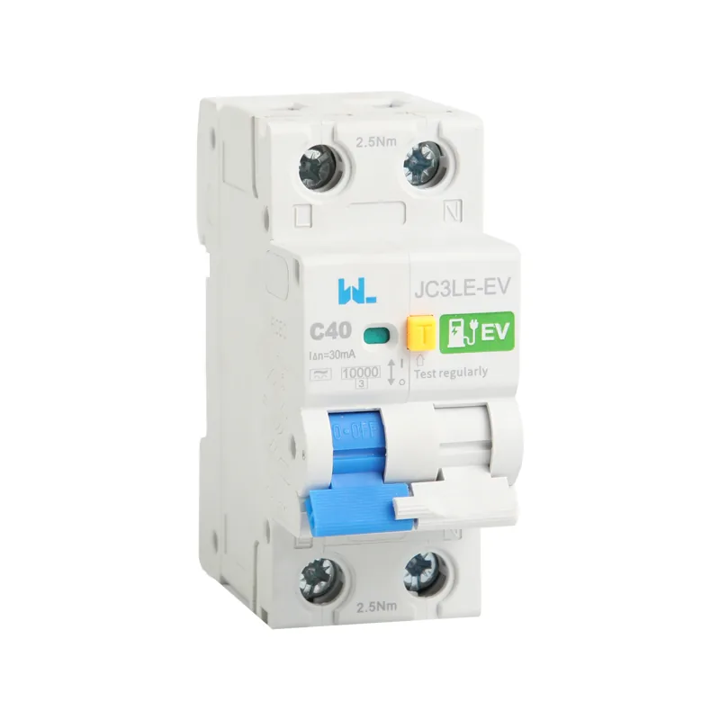
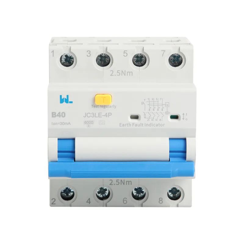
For a four-pole product reference, review the JC3LE 4P electromagnetic RCBO and request its model-specific wiring diagram, ratings and destination-market documentation. W9 Group can discuss the product selection, while the project designer remains responsible for the complete protective arrangement and verification plan.
よくある質問
What is the difference between RCBO and RCCB?
An RCBO combines residual-current and overcurrent functions for one circuit. An RCCB provides residual-current protection only and normally works with separate MCBs for overload and short-circuit protection. In an RCBO vs RCCB comparison, circuit grouping, selectivity and panel space usually drive the choice.
Does an RCBO replace an MCB?
For the functions covered by its product rating, an RCBO can replace the branch MCB and separate RCCB. Confirm the declared short-circuit capacity, voltage, curve and installation category; an RCBO is not automatically suitable for every feeder.
Why does my RCBO trip when nothing appears faulty?
Aggregate leakage from filters, drives, heaters or long cables can approach the device threshold. Incorrectly shared neutrals and waveform mismatch are common causes. Isolate branches methodically, measure leakage with suitable instruments and check the wiring diagram before changing sensitivity.
How often should an RCBO be tested?
Use the test button and inspection interval required by the local installation rules, workplace policy and manufacturer instructions. Periodic verification should also include functional and instrument tests by a competent person, especially after modifications or faults.
Can one RCBO protect an EV charger?
It can when its residual-current type, pole arrangement, rating and coordination match the charger instructions and local code. Some chargers require additional DC-sensitive measures; review the complete protective scheme rather than selecting by ampere rating alone.
参考文献
- IET — どのタイプのRCDですか?. September 2019 explanation of residual-current waveforms and type selection. Accessed 16 October 2026.
- IET — BS 7671:2018+A2:2022におけるRCD試験の変更点. July 2022 installation-test context; apply the rules adopted for the project. Accessed 16 October 2026.
- IET — 電気自動車充電設備用機器(EVSE)向けRCD. May 2024 EV protection architecture under the stated BS 7671 edition. Accessed 16 October 2026.
Design principle: let the smallest practical protective zone take the trip, and prove that decision with calculations, coordination data and commissioning records.
Ready to review a branch schedule or OEM bill of materials? Browse the protection range and contact W9 for application and documentation support.