






ACユニットにSPDを設置する手順(ステップバイステップガイド)
An air-conditioner SPD can be correctly labelled yet poorly applied if the supply topology, earthing or connecting conductors are wrong. Selection and installation must follow the exact device instructions and local electrical requirements, not a universal voltage multiplier or a guessed wire-colour diagram.
A surge protective device limits transient overvoltage within its declared duty. It does not guarantee that equipment will survive every lightning event, correct a sustained supply overvoltage or replace the circuit breaker. This guide is a planning and acceptance sequence for qualified installation, not a live-wiring recipe.
Step one: identify the circuit and protection location
Record the air conditioner’s supply voltage, phase arrangement, neutral and protective-earth arrangement, disconnect location and existing surge protection. Determine whether the proposed SPD belongs at the origin, a distribution board or near the equipment. Device Type and mounting location must be permitted by its documentation and the destination rules.
Do not treat every 240 V system as the same connection. Line-to-line, line-to-neutral and earthing arrangements affect the appropriate protective modes. The equipment maker’s instructions and actual circuit diagram control the selection.
The AC surge protection guide explains the difference between transient limitation and sustained-overvoltage protection.
Step two: compare the complete SPD ratings
確認 maximum continuous operating voltage Uc, protection level Up, Type, discharge-current declarations and temporary-overvoltage behaviour. A larger Imax number is not a complete ranking. Compare like test waveforms and the required protection duty; a Type 2 Imax value is not interchangeable with a Type 1 impulse-current declaration.
Do not select Uc using a universal percentage or Up using “lower is always better.” Both must fit the system and equipment withstand, while avoiding unsuitable continuous stress. A joule number by itself is also insufficient for selecting a hardwired SPD.
| フィールド | Decision it supports | 制限事項 |
|---|---|---|
| Uc | Continuous supply compatibility | Not the same as clamping voltage |
| Up | Declared protection level under test | Installed lead effects remain relevant |
| Type and current duty | Required surge test and location | Compare matching waveforms |
| Backup protection | Fault coordination and disconnection | Use exact manufacturer instructions |
| Enclosure | Suitability for installed environment | A bare DIN-rail module may need an enclosure |

Step three: prepare isolation and installation
A qualified installer must identify all supplies, isolate, secure against reconnection and prove absence of voltage using an appropriate procedure and instruments. An open handle, elapsed waiting time, sticky-note warning or non-contact indication alone does not establish safe isolation. Follow equipment-specific stored-energy instructions.
Before work begins, check enclosure space, terminals, conductor requirements and backup protection. The SPD drawing determines the connections. Do not infer terminal functions from wire colour alone or reuse a wiring photograph as the sole installation instruction.
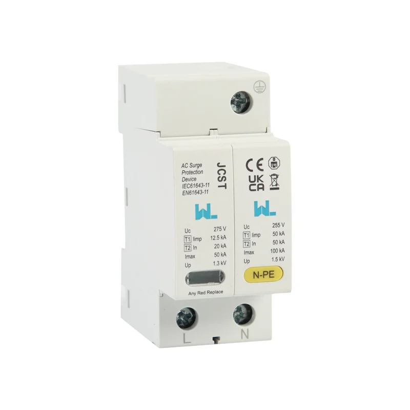
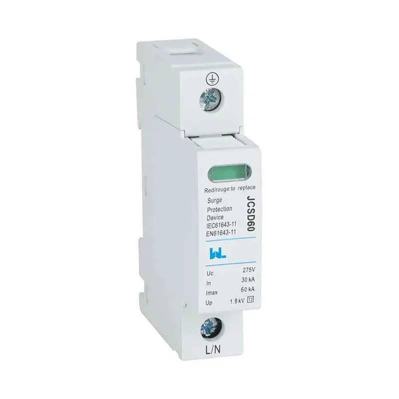
「use」を Type 1+2 SPD listing as a model reference and request its current wiring and backup-device instructions.
Step four: control the connection path
Connection length and routing can affect the voltage appearing at the protected equipment during a transient. Keep the arrangement within the manufacturer’s limits and the applicable installation rules. Avoid unnecessary loops and coordinate with the actual bonding arrangement rather than adding an independent unverified earth path.
| Installation review | 受容の証拠 |
|---|---|
| 隔離 | Approved procedure and verified absence of voltage |
| Wiring | Exact SPD drawing and identified terminals |
| Conductors | Specified size, route and terminal torque |
| Backup device | Approved type and rating |
| Final condition | Enclosure closure, identification and status indication |

Step five: verify and plan replacement
Inspect the completed work and check the status indication according to the product instructions. Document the model, protective modes, backup device and installation location. An indicator does not prove the complete earthing system or guarantee protection of every downstream item.
Define inspection and replacement responsibility. An exhausted module must be replaced with a compatible part after the cause and installation have been reviewed. An SPD is a maintainable protective component, not a lifetime guarantee against damage.
Documentation for an HVAC project
IEC 61643 product references and installation requirements have different scopes; U.S. projects may require a separate listing and installation route. Confirm the exact edition and destination-market requirement rather than treating a catalogue mention as universal approval. Request W9’s model-specific diagram and supporting documents with the enquiry.
よくある質問
Does an SPD prevent every air-conditioner failure?
No. It limits transient overvoltage within its declared scope. It does not correct all supply faults or prevent mechanical and other electrical failures.
Is 40 kA enough for any air conditioner?
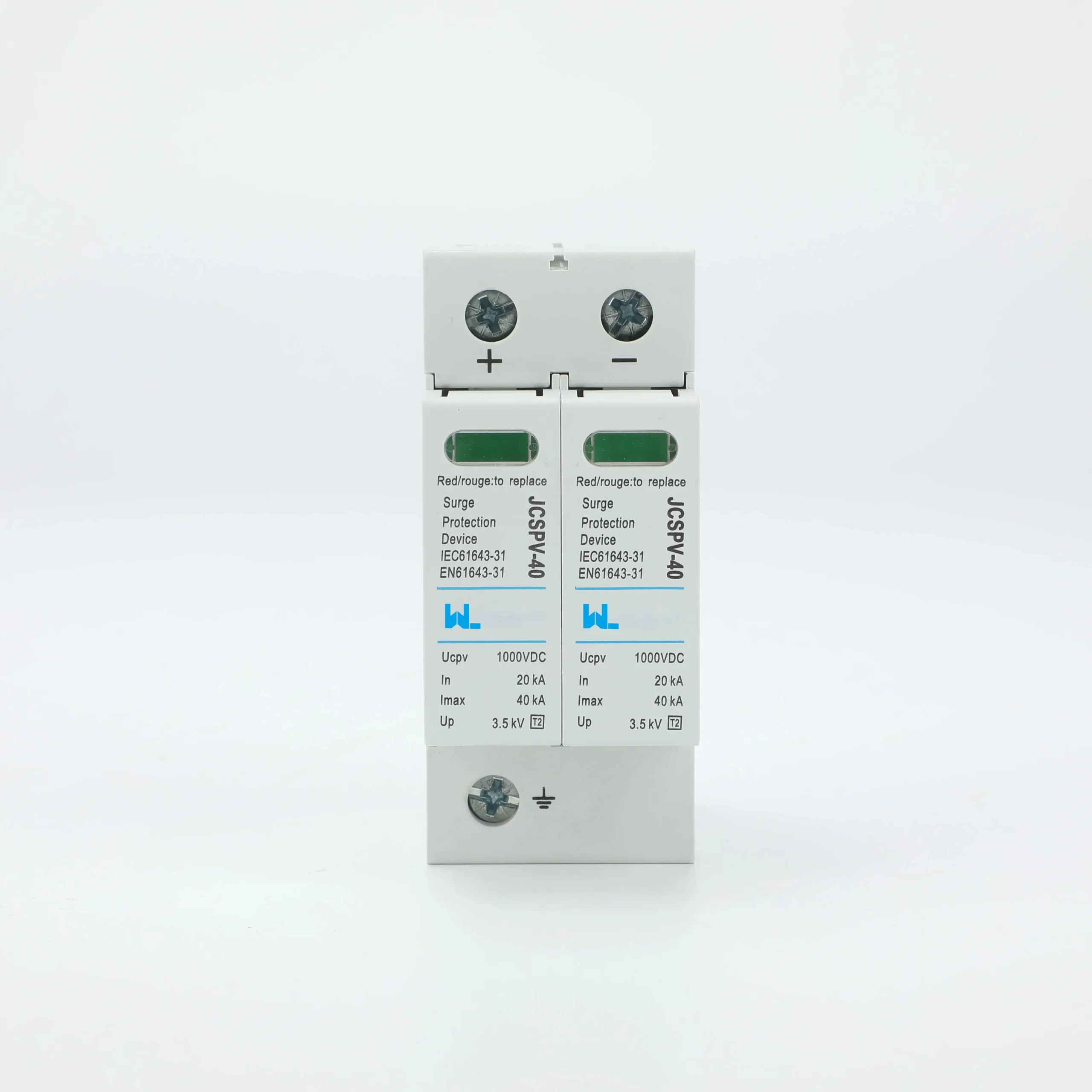
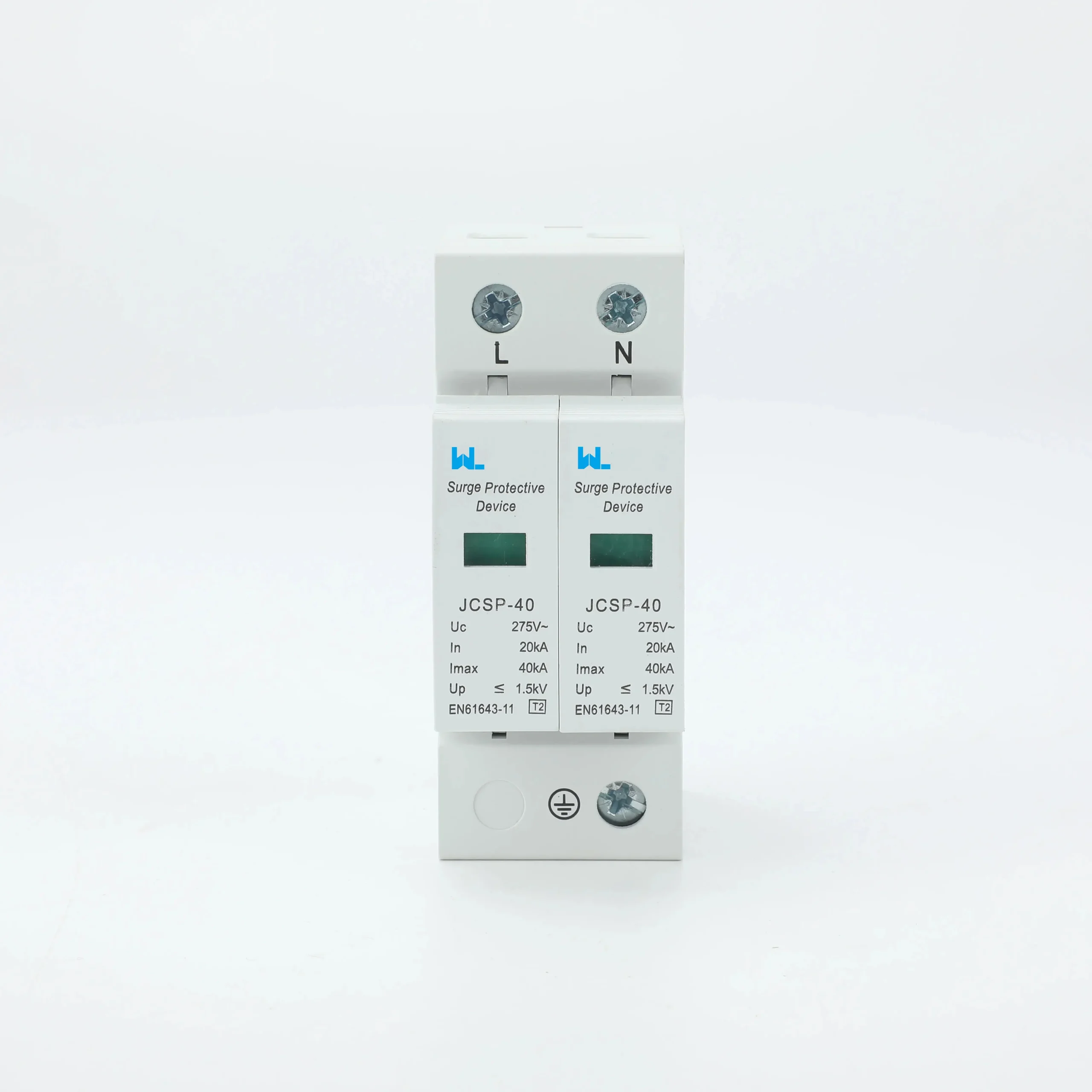
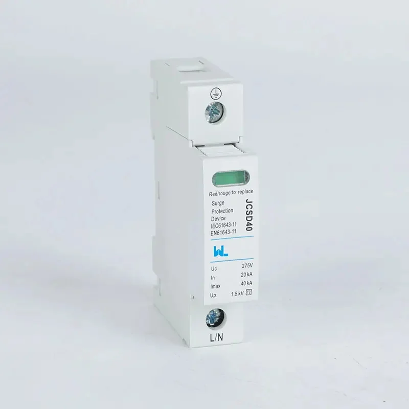
A current number alone cannot establish suitability. Check supply topology, Uc, Up, Type, protection modes, backup protection and the installation location.
Can I install an SPD using a generic wiring diagram?
Use the exact manufacturer’s diagram and qualified installation under local rules. Generic diagrams can omit important differences in earthing, supply and protective modes.
Does a green indicator prove the whole installation is protected?
No. It indicates the state defined by the manufacturer. Correct wiring, bonding, coordination and equipment protection remain separate checks.
参考文献
- IET — BS 7671 installation-rules scope.
- HSE — electrical safety and competent work.
- IEC catalogue — verify the applicable IEC 61643 edition and product scope.
For an SPD review, W9グループへのお問い合わせ with the supply arrangement, protection location, equipment withstand and installation constraints.