































Understanding the Role of MCCB in Photovoltaic Distribution Lines
Understanding the Role of MCCB in Photovoltaic Distribution Lines
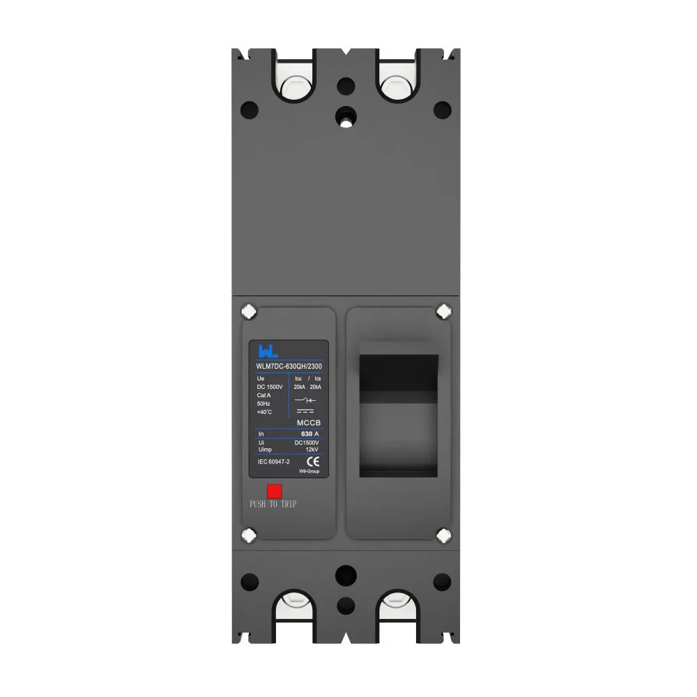
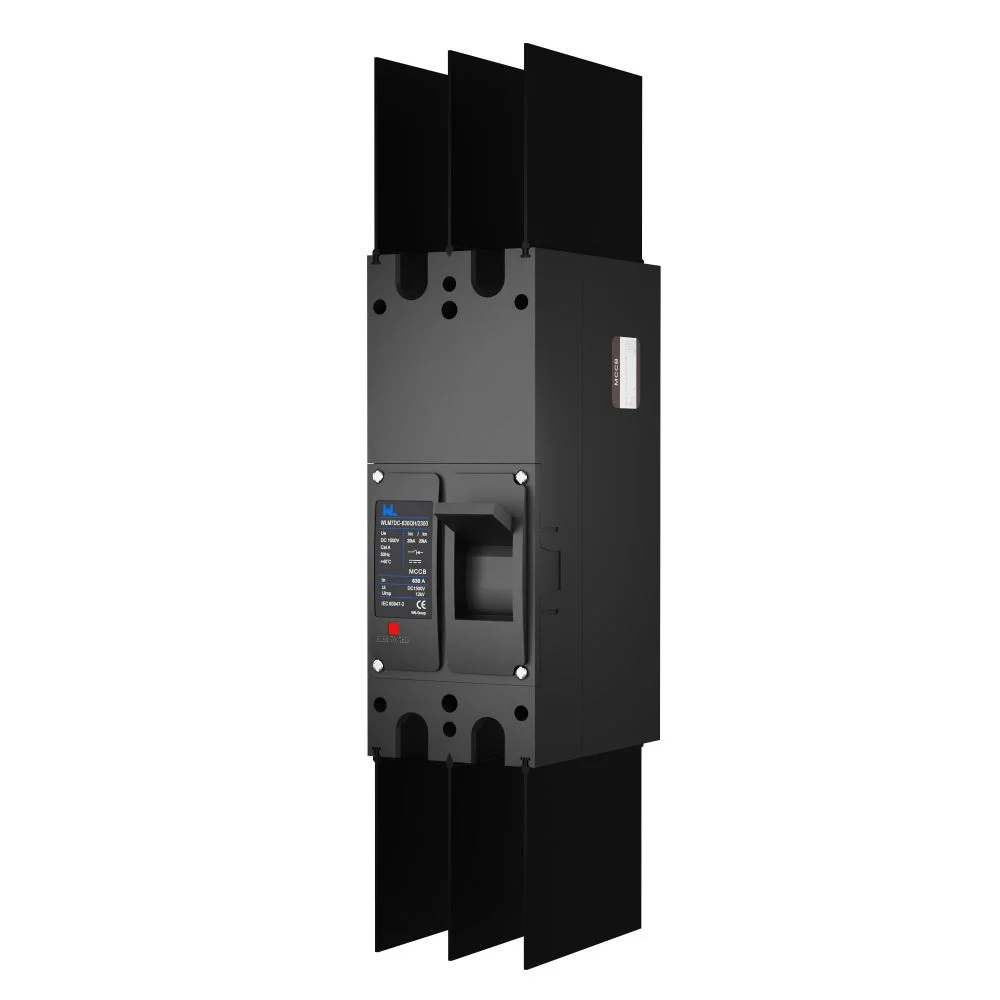
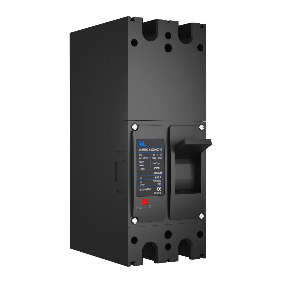
When Priya, an EPC commissioning lead in Pune, closed the feeder breaker on a rooftop array, the combiner cabinet flashed and the inverter stopped with a persistent insulation alarm. The crew replaced the breaker, checked the terminations and tried again; the same visible failure returned within seconds. A review showed that an AC-rated device had been specified for a DC feeder, with polarity and interruption duty left to assumption. Root cause: selection, not product failure.
Summary: A photovoltaic MCCB must be selected for the circuit’s actual DC voltage, polarity, continuous current, prospective fault current and isolation method. IEC 60947-2 covers circuit-breaker requirements, while IEC 60947-1 supplies common rules; neither standard makes an AC breaker suitable for DC by default. Map the string-to-inverter path, apply the governing installation code (such as NFPA 70 Article 690), verify manufacturer derating and coordinate the device with the SPD before release for construction.
In a PV plant, molded-case circuit breakers sit at string, combiner, inverter-input and auxiliary-feeder boundaries. They provide selective interruption and safe isolation, helping an EPC show that the PV distribution line was designed as a system.
Where an MCCB fits in the PV power path
Start with a one-line diagram. Individual strings feed a combiner box, parallel outputs travel on a DC collection or PV distribution line, and an inverter converts DC to AC before the transformer and grid interconnection. A breaker at each boundary has a different duty: string protection may address reverse current, a combiner feeder may carry the sum of many strings, and an inverter input breaker must withstand the array’s maximum operating voltage and available fault energy.
Photovoltaic modules can supply current while illuminated, so opening DC is not equivalent to opening AC at a current zero. A DC MCCB uses a specified magnetic arrangement, pole series connection and arc chamber to extinguish the arc. Follow the manufacturer’s wiring diagram; changing polarity or pole connection can invalidate interruption capability. This is the core distinction in photovoltaic MCCB selection.
Voltage and polarity come before frame size
Record maximum open-circuit voltage at the lowest design temperature, then compare it with the breaker rating for the exact pole count and connection. A 1,000 VDC device is not automatically acceptable on a 1,500 VDC circuit. Mark conductors, follow the specified polarity arrangement for the photovoltaic MCCB, and confirm whether both poles must isolate under the destination code.
Interrupting a DC fault without creating a second hazard
Solar circuit protection must clear a fault sustained by parallel strings. Module characteristics and conductor impedance limit current, but the arc can persist until fully de-energized. IEC 60947-2 tests making, breaking and short-circuit performance; request the test configuration, DC voltage, pole arrangement and utilization category for your installation.
Prospective fault current also changes along the line. A combiner output can see contribution from every connected string, while a string fuse or breaker sees only its local sources. Protection should be located so a faulted section is isolated while healthy sections remain available. This is the practical meaning of selectivity: time-current curves, instantaneous settings and upstream/downstream device data are compared as a coordinated set, not chosen in isolation.
Illustrative sizing calculation
Illustrative only: assume 12 strings with a design operating current of 13 A each. The combiner output current is 12 × 13 A = 156 A. If the applicable code requires a 125% continuous-current factor, the design basis becomes 195 A (156 A × 1.25). The engineer would then check conductor ampacity, ambient and enclosure derating, available fault current, terminal temperature and the manufacturer’s permissible setting before selecting a frame and trip unit. The calculation does not prescribe a 200 A breaker or any other rating for a real project.
| Decision point | AC MCCB | DC MCCB |
|---|---|---|
| Arc interruption | Benefits from the AC current zero each cycle; tested at specified AC frequency. | Must sustain and extinguish a continuous arc; verify DC test voltage and pole series arrangement under IEC 60947-2. |
| Voltage notation | Rated in volts AC with frequency and phase assumptions. | Rated in volts DC for a stated pole count and polarity; never infer equivalence from the frame label. |
| Installation role | Typically inverter output, auxiliary or utility feeder. | String, combiner and inverter-input protection on the PV distribution line. |
| Isolation | Follow the equipment and local code; neutral switching may be relevant. | Often requires simultaneous positive/negative isolation and clearly marked polarity. |
| Maintenance risk | Verify backfeed and stored energy before work. | Expect daylight generation, capacitor energy and persistent arc risk; use a documented lockout procedure. |
Coordination with SPDs, inverters and maintenance
An SPD is not a substitute for an MCCB. IEC 61643-31 addresses SPDs on the DC side of PV installations, while IEC 61643-11 covers low-voltage AC SPDs. The upstream protective device must be compatible with the SPD’s backup-fuse requirement and let-through energy. Check lead length, short-circuit withstand and the inverter maker’s coordination instructions; a breaker that trips too readily can interrupt protection, while one that is too slow can leave an SPD damaged after a surge.
Show isolation points on the one-line and label them at the combiner and inverter. Confirm that the inverter’s DC switch, external DC MCCB and any fuse are intended to work together. During maintenance, test both polarities, account for daylight and stored capacitor energy, and follow lockout/tagout. Retain torque, insulation and trip-test records for handover; this discipline is part of effective solar circuit protection.
| Location | Primary risk | Questions for the design review |
|---|---|---|
| String or sub-array | Reverse current and connector faults. | Is overcurrent protection required by module and code instructions? Is the device rated for the string voltage and polarity? |
| Combiner output | Combined current and fault contribution from parallel strings. | What is the calculated continuous current, derating envelope and prospective DC fault current? |
| Inverter input | Persistent DC arc and inverter backfeed or capacitive energy. | Does the inverter manual specify a breaker type, pole connection, coordination or external isolator? |
| Inverter AC output | Grid fault and utility protection requirements. | Use an AC-rated device and coordinate with transformer, utility relay and NFPA 70 Article 705 where applicable. |
Standards, codes and evidence to request
IEC 60947-1 sets common low-voltage switchgear rules; IEC 60947-2 covers circuit breakers and their test duties. IEC 62548 provides PV array design and safety guidance, including wiring, isolation and protection concepts. In North America, UL 489 generally covers molded-case circuit breakers, while UL 98 covers enclosed and dead-front switches; the labels address different product functions and should not be treated as interchangeable evidence. NFPA 70 Articles 690 and 705 add installation rules for PV systems and interconnected sources. Applicability depends on the destination market, equipment listing and edition adopted by the authority having jurisdiction.
Request a datasheet, installation diagram, terminal and torque instructions, time-current curves, DC short-circuit test details, SPD backup-device guidance and a declaration of the standards used. A certificate for one configuration does not automatically cover another pole connection or voltage. Unsupported certification language in a tender can create rejection, redesign and warranty exposure even when the hardware operates normally.
Selection checklist for procurement and commissioning
- Map the circuit: identify every string, combiner, inverter and possible backfeed path on the PV distribution line.
- Freeze design inputs: maximum DC voltage, polarity, continuous current, ambient temperature, enclosure conditions and prospective fault current.
- Verify the device: confirm photovoltaic MCCB test duty, DC pole series arrangement, utilization category, terminal limits and derating data under IEC 60947-2.
- Coordinate protection: compare curves for selectivity, check SPD backup requirements and align with the inverter manual and local code.
- Plan isolation and records: label both poles, define lockout steps, and retain torque, insulation and trip-test records for handover.
For buyers comparing sources, Zhejiang W9 Group Technology Co., Ltd. (founded in 2020) supplies low-voltage protection products and can discuss OEM/ODM configuration, documentation and testing support. Review the exact WLM7DC product information for your application—WLM7DC photovoltaic MCCB—without assuming that a catalog family covers every project voltage or connection.
For background on device construction, see our DC MCCB basic guide. The AC SPD coordination overview and circuit-breaker application guide provide useful commissioning context.
Frequently asked questions
Can an AC MCCB be used on a photovoltaic DC circuit?
Not by default. Use a device with a verified DC rating and test configuration for the circuit voltage, pole count and polarity; an AC label alone does not demonstrate DC arc interruption.
Where should a photovoltaic MCCB be installed?
Common locations are combiner outputs and inverter inputs, with the exact point set by the array design, inverter instructions and local code. The one-line should show each isolation point and any possible backfeed.
How is a DC MCCB sized for continuous PV current?
Calculate the circuit current from the connected strings, apply the continuous-current rule required by the governing code, then check conductor ampacity, temperature derating, terminals and fault current. Treat any numerical example as a design aid, not a substitute for project calculations.
Does an SPD replace the breaker on a PV feeder?
No. The SPD limits transient overvoltage; the MCCB provides overcurrent interruption and isolation. Confirm the SPD’s specified backup protection and energy coordination with the breaker manufacturer.
What documents should an EPC request from an MCCB supplier?
Request the datasheet, DC test details, wiring and pole diagrams, derating curves, time-current curves, installation torque values and standards declarations. Add routine-test or inspection records when required by the contract, without accepting unverified certification claims.
Authoritative references
- International Electrotechnical Commission, IEC 60947-1 and IEC 60947-2 low-voltage switchgear standards.
- International Electrotechnical Commission, IEC 61643-31 and IEC 61643-11 surge-protective-device standards.
- International Electrotechnical Commission, IEC 62548 photovoltaic array design requirements.
- NFPA 70 (National Electrical Code), Articles 690 and 705.
- UL Solutions, UL 489 circuit breakers and UL 98 enclosed switches.
The reliable rule is simple: interrupt the fault you calculated, at the voltage you measured, with the polarity and coordination you documented. When you are ready to review options, visit our low-voltage protection products page and contact W9 with your one-line, design inputs and destination standard.