































How to Choose the Right Thermal Magnetic Circuit Breaker: Practical Tips
How to Choose the Right Thermal Magnetic Circuit Breaker: Practical Tips
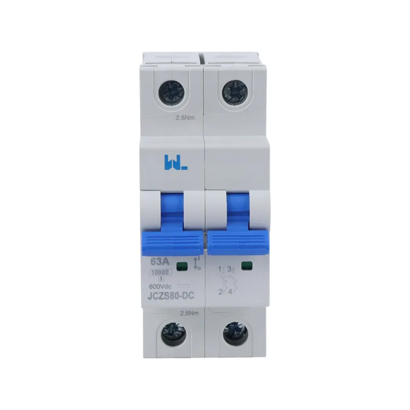
When a project engineer in Manchester accepted a low-price quotation and fitted a thermal magnetic breaker without checking the fault study, the test run ended in nuisance trips and a failed inspection. The breaker itself was functional; the schedule had ignored conductor capacity, motor inrush and the standard used to declare breaking capacity. That experience leads to the question buyers actually need answered: how does a team choose a thermal magnetic circuit breaker that will trip at the right time, in the right way, for the real installation?
Summary: The right thermal magnetic circuit breaker matches design current, cable ampacity, prospective fault current, voltage, poles and load inrush. Its thermal release handles sustained overloads; its magnetic release clears high-current faults quickly. Use the applicable IEC product standard (typically IEC 60898-1 for household/similar MCBs or IEC 60947-2 for industrial breakers), verify Icu/Ics or Icn, and document coordination before purchase.
A thermal magnetic breaker combines a heat-responsive bimetal and an electromagnetic trip. The bimetal bends when current remains above its rated value, creating a time delay that allows brief starting currents. A magnetic solenoid reacts to a severe surge, such as a short circuit, and opens the contacts almost instantaneously. This dual response is why the device remains popular in distribution boards, motors and OEM machinery. Selection is still an engineering decision: a familiar ampere label cannot prove that the breaker protects the cable or interrupts the available fault current.
1. Start with the electrical duty, not the catalogue
Before comparing brands, record four values from the design: load current (Ib), protective-device rating (In), conductor capacity (Iz) and prospective short-circuit current at the installation point. IEC 60364-4-43 expresses the basic coordination principle as Ib ≤ In ≤ Iz; local wiring rules may add correction factors. Ambient temperature, enclosure grouping and altitude can derate a breaker, so the nameplate current may not be the usable continuous current.
- Voltage and poles: confirm AC system voltage, frequency, neutral switching and whether a 1P, 2P, 3P or 4P device is required.
- Fault level: choose a declared interrupting capacity above the calculated prospective fault current; do not substitute a marketing “short-circuit rating” for a test value.
- Load profile: note heaters, LED drivers, transformers, motors and welders whose inrush can be several times steady-state current.
- Environment: check enclosure temperature, humidity, dust and vibration against the manufacturer’s operating limits.
2. Understand the thermal and magnetic trip curve
Thermal release: protection against time-dependent overload
The bimetal responds to I²t heating. A modest overload may take seconds or minutes to trip, while a larger overload bends the strip faster. This delay protects motors and transformers during normal starting, but it cannot be treated as a fixed timer. IEC 60947-2 requires time-current performance to be verified at declared reference conditions; the actual trip time changes with ambient temperature and pre-heating.
Magnetic release: fast interruption of high current
The magnetic coil trips when current reaches its instantaneous threshold. For MCBs under IEC 60898-1, B, C and D curves indicate different instantaneous ranges: B is commonly selected for low-inrush circuits, C for general commercial loads, and D for high-inrush transformers or motors. The exact multiples and tolerances belong to the declared product standard and model data sheet. Selecting a D curve merely to stop nuisance tripping can be unsafe if the loop impedance cannot deliver enough fault current for the required disconnection time.
3. Select ratings that coordinate with the system
| Parameter | What to verify | Why it matters |
|---|---|---|
| Rated current (In) | Load calculation, conductor ampacity and derating | Prevents cable overheating and unwanted trips |
| Rated voltage (Ue) | System voltage, frequency and insulation level | Ensures dielectric and switching performance |
| Breaking capacity | Icn under IEC 60898-1, or Icu/Ics under IEC 60947-2 | Confirms the device can interrupt the available fault |
| Trip curve/settings | B/C/D curve or adjustable long-time/instantaneous settings | Balances inrush tolerance and fault clearing |
| Poles and neutral | 1P–4P arrangement and switched-neutral policy | Provides the intended isolation and phase protection |
| Temperature correction | Reference ambient (often 30–40 °C) and enclosure data | Keeps continuous rating realistic |
For a feeder with a high available fault current, an MCCB may be more appropriate than a fixed-curve MCB because its adjustable long-time and instantaneous settings can improve selectivity. For a final lighting circuit, an MCB with a documented curve and Icn may be sufficient. The distinction between MCB and MCCB functions is therefore about duty and coordination, not simply physical size.
4. Compare thermal magnetic breakers with other protection options
| Device | Primary protection | Best fit | Limitation to check |
|---|---|---|---|
| Thermal magnetic MCB | Overload plus short circuit | Final circuits and small equipment | Limited adjustment; curve must suit inrush |
| Thermal magnetic MCCB | Higher-current overload and short circuit | Feeders, motors and industrial incomers | Verify Icu/Ics, derating and coordination |
| Electronic MCCB | Adjustable L/S/I (and sometimes G) functions | Complex distribution and selectivity studies | Requires settings, auxiliary power or testing procedure |
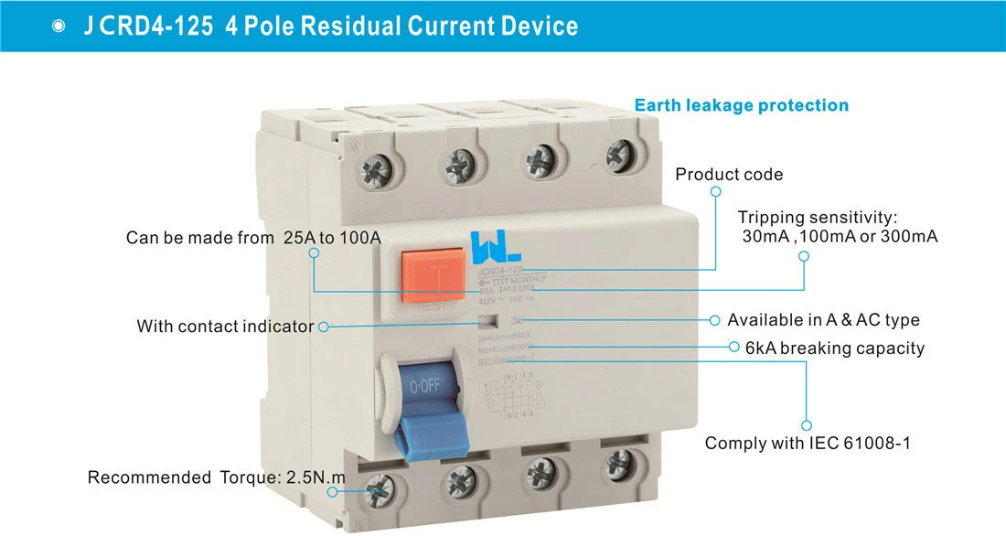
| RCCB/RCD | Residual-current imbalance | Leakage and additional shock protection | No integral overcurrent release; pair with MCB/fuse |
| RCBO | Residual current plus overcurrent | Individual circuits where space/selectivity matter | Check type, neutral routing and IEC 61009-1 scope |
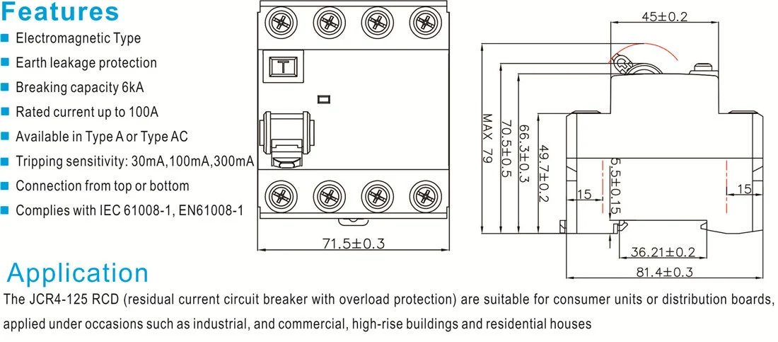
A residual-current device does not replace a thermal magnetic breaker unless its product explicitly includes overcurrent protection. IEC 61008-1 covers RCCBs without integral overcurrent protection; IEC 61009-1 covers RCBOs. This distinction prevents a common procurement error in which a leakage device is expected to protect a cable from overload.
5. Apply IEC standards and conformity checks
Use the standard that matches the application. IEC 60898-1 addresses circuit-breakers for household and similar installations; IEC 60947-2 covers low-voltage circuit-breakers used in broader industrial contexts. IEC 60364-4-43 governs installation principles for overcurrent protection, while national adoptions and inspection rules remain mandatory. A product certificate does not certify the complete installation: the design still needs a fault calculation, conductor coordination, protective settings and commissioning records.
Ask the supplier for the exact model’s declaration, certificate scope, test report, pole configuration, temperature derating and time-current curves. Confirm whether the quoted breaking capacity is Icn, Icu or Ics; these terms are not interchangeable. Keep the documents with the panel so a replacement device can be matched later without guessing.
6. A practical buyer checklist
- Calculate: establish Ib, Iz, fault current and inrush for every circuit.
- Choose the family: MCB for final circuits, MCCB for higher-current feeders, or an electronic trip unit where selectivity requires it.
- Set the curve: select B, C or D only after checking starting current and fault-loop impedance.
- Coordinate: compare upstream and downstream curves; verify backup protection and discrimination at the maximum fault.
- Inspect installation: torque terminals to the manufacturer’s value, maintain clearances and record insulation/functional tests.
- Plan lifecycle: specify spare identification, accessories, test intervals and environmental derating for future replacements.
W9 Group, Zhejiang W9 Group Technology Co., Ltd., established in 2020, describes a China-based low-voltage protection portfolio spanning MCB, RCCB/RCD, RCBO, MCCB, SPD, AFDD, switch-disconnectors, contactors and smart products. The company reports inspection, testing, ageing checks and OEM/ODM support, and says products are developed with reference to IEC, CE, TUV, UL and relevant requirements. Buyers should verify model-level evidence. For example, the WLM6E-400A-3300 is described as a 3-/4-pole electronic MCCB rated 400 A with 400–690 V working-voltage options; confirm the current catalogue, trip-unit configuration and certificates before approval. Review the W9 Group low-voltage protection range and request technical support for the intended market.
Frequently asked questions
How do I choose the ampere rating of a thermal magnetic breaker?
Start with the calculated design current and conductor ampacity. Select a rated current that satisfies Ib ≤ In ≤ Iz after ambient and grouping derating; then verify voltage and breaking capacity against the fault study.
Which curve is better, B, C or D?
None is universally better. B suits low-inrush loads, C tolerates moderate inrush, and D tolerates higher inrush from motors or transformers. Confirm exact trip multiples and disconnection time under IEC 60898-1 and local rules.
Is an MCCB always safer than an MCB?
No. An MCCB offers higher ratings and often adjustable protection, but safety depends on correct settings, fault capacity and coordination. A properly selected MCB can be the right device for a final circuit.
Can an RCCB replace a thermal magnetic breaker?
No. An RCCB under IEC 61008-1 detects residual current but has no integral overcurrent release. Pair it with an appropriately rated MCB or use an RCBO under IEC 61009-1 when combined protection is required.
What documents should a supplier provide?
Request the model data sheet, declaration, certificate scope, test report, time-current curves, derating information, wiring diagram and coordination data. Match every document to the exact catalogue number and destination market.
References
- IEC Webstore: IEC 60947-2, Low-voltage switchgear and controlgear—Circuit-breakers.
- IEC Webstore: IEC 60898-1, Circuit-breakers for household and similar installations.
- IEC Webstore: IEC 61008-1 and IEC 61009-1 residual-current devices.
- IEC Webstore: IEC 60364-4-43, Protection against overcurrent.
The difference is not merely the ampere number on the handle—it is the quality of the duty calculation, the trip curve and the evidence behind the choice. W9 Group builds low-voltage protection products for that decision point; review the technical support resources and contact W9 Group for model-specific documentation before the schedule is frozen.