





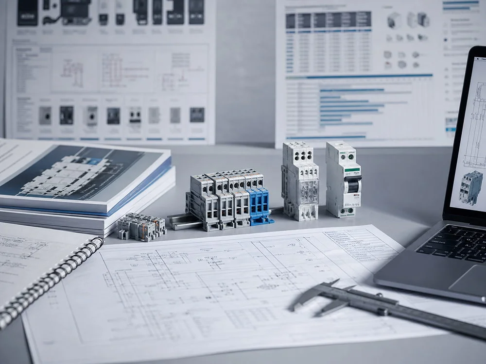


Guía completa para principiantes: Símbolos de interruptores aisladores en diagramas de circuitos
An open-switch mark on a drawing cannot establish that a work area is isolated. A beginner must read the symbol together with its device tag, legend, pole schedule and every possible supply path. The useful distinction is between what the drawing communicates and what the installed, rated device is permitted to do.
Summary: An isolator switch symbol shows a deliberate switching and isolation function; it does not automatically mean overcurrent protection. IEC 60617 provides the graphical-symbol language, while IEC 60947-3 covers many low-voltage switch-disconnectors and disconnectors. Read the symbol with its pole count, device tag, source direction and notes, then verify that the selected switch is rated for the actual voltage, current and utilization category. For beginners, the safest action is to trace every possible supply, open the identified device, lock and label it, and prove dead with an approved test method before work starts.
What the isolator symbol means
In a simplified circuit diagram, an isolator is usually represented by a movable contact separated from a fixed contact when open. The diagonal blade communicates “off” or “disconnected”; a closed position shows contact touching. A professional drawing adds a reference such as Q1, a device description, pole count and schedule entry. A symbol by itself is not a product datasheet.
A disconnector provides an isolation function under its declared conditions; a switch-disconnector also has a stated switching duty. Neither provides automatic overload or short-circuit protection merely because it appears beside an upstream breaker. A circuit-breaker adds a protective interruption function, and its suitability for isolation must also be established. Read the legend and schedule rather than assigning every open-contact symbol the same capability.
Circuit Symbol Identification
A single-line diagram may use a simplified representation for a multi-pole device, while a wiring diagram shows individual conductors and contacts. Mechanical links, tags and annotations need the drawing’s legend and drafting convention. A padlock note describes a required operating arrangement only when matched to suitable hardware. An earth symbol may refer to a separate bonding or earthing function; it does not turn a nearby isolator into an earthing switch.
| Drawing clue | Likely meaning | Check before work |
|---|---|---|
| Open blade or separated contact | Switch or disconnector shown open | Confirm whether it is rated for load breaking or isolation only. |
| Several linked blades | Two-, three- or four-pole switching | Verify which conductors are switched and whether neutral must open. |
| Q or QS reference with “main switch” | Identified switch-disconnector in the schedule | Match tag, catalog number, Ue, In and utilization category. |
| Dashed mechanical link | Poles operate together | Check simultaneous operation and handle position indication. |
| Padlock, key or L/O note | Lockout or controlled access requirement | Confirm lockable hardware and the site’s isolation procedure. |
| Earth symbol or “ES” tag | Separate earthing switch or bonding point | Never assume an ordinary isolator is an earthing switch. |
IEC 60617 is a symbol vocabulary, not a safety procedure. A local drafting standard can add conventions for line style, device tags and normal-state depiction. Ask for the legend when a supplier drawing and an owner’s single-line diagram disagree. A familiar-looking symbol can still hide a switched neutral, control feed or automatic transfer source.
When reviewing a supplier drawing, ask for a short cross-reference: symbol and tag, normal state, number of switched poles, protective function if any, load-switching category and evidence document. This gives an installer a practical route from the schematic to the supplied device. An ambiguous icon should become a drawing query, not an on-site assumption about load breaking, neutral behavior or lockout.
Isolation Device Comparison
A disconnector is selected for isolation, while a switch-disconnector combines isolation with declared making and breaking duties. Do not operate a disconnector outside its specified switching conditions. A circuit-breaker adds automatic overcurrent interruption. Some products combine roles, but each claimed function needs its own declared scope; the schematic icon alone proves none of the electrical ratings.
| Device shown in the drawing | Primary job | Typical evidence to request | Common beginner error |
|---|---|---|---|
| Disconnector / isolator | Visible or positively indicated separation for maintenance | Isolation distance, pole arrangement, mechanical endurance and installation instructions | Opening it under a fault and expecting breaker protection |
| Switch-disconnector | Routine switching plus isolation within a utilization category | IEC 60947-3 category, rated operational current and making/breaking test data | Ignoring motor, capacitor or PV DC duty |
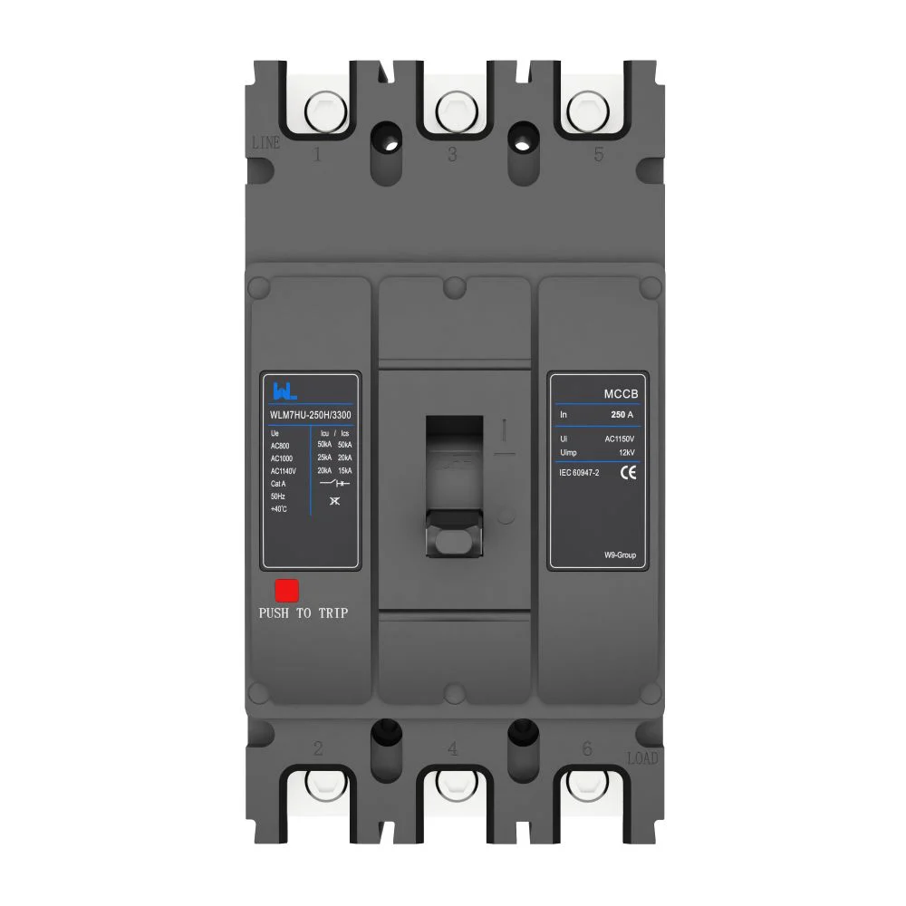
| MCB or MCCB | Automatic overload and short-circuit protection, often with switching | IEC 60898-1 or IEC 60947-2 ratings, Icu/Ics and trip curve | Calling every breaker symbol an isolator |
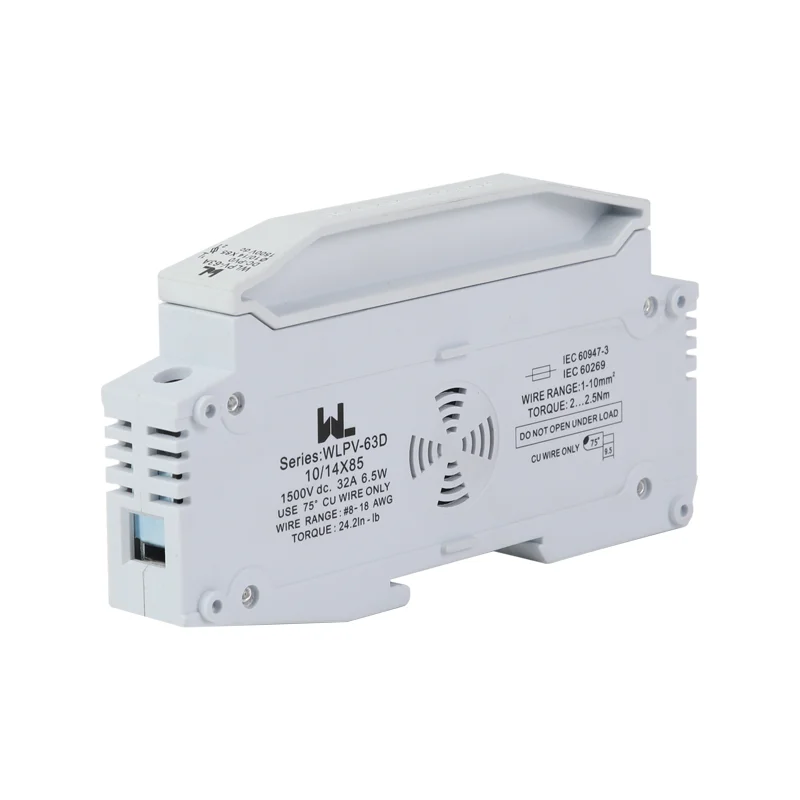
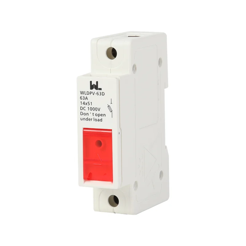
| Fuse-switch or fused isolator | Isolation combined with replaceable fuse protection | Fuse-link type, short-circuit rating, heat dissipation and spare specification | Substituting a fuse without checking the switch body |
Isolator Circuit Diagram Interpretation
Start at the source and follow the conductor to the load. Identify every incoming path: utility, generator, inverter, UPS, control transformer and stored-energy source. Mark upstream and downstream sides, then count conductors. A three-pole symbol may leave the neutral continuous; a four-pole device may disconnect it only if the earthing arrangement and local rules permit. In a PV or battery circuit, polarity and DC arc behavior require dedicated verification.
Compare the device tag with the schedule, exact catalogue number, operational voltage, current, poles and utilization category. An illustrative label such as QS1, 4P, 125 A, 400 V AC, AC-22A states more than an unlabelled blade, but still needs the corresponding model evidence. Review conditional short-circuit ratings and the required upstream protective device instead of assuming the switch will clear a fault by itself.
Isolator Operating States
Drawings may depict equipment in its normal, de-energized or process state; read the legend and title block. A normally open contact in a control circuit is not the same as the open position of a maintenance isolator. During commissioning, record the as-left position, label the enclosure and test the indication. An auxiliary contact can report “open” while a separate back-feed remains live, so indication is helpful evidence but not proof of absence of voltage.
Show every isolation boundary
Mark utility, generator, UPS, inverter, control and stored-energy sources before deciding which device must open. A stopped motor or an open position contact is not proof of absence of voltage. The safe-work procedure must specify isolation, lockout, discharge where applicable and verification with suitable equipment by competent personnel. Resolve discrepancies between the as-built diagram and field labels before authorizing work.
Isolator Compliance Requirements
Use IEC 60617 for graphical language, then apply IEC 60947-3 to many industrial switch-disconnectors, switches and disconnectors. IEC 60364-5-53 addresses selection and erection in low-voltage installations. In North American projects, NFPA 70 (NEC) disconnecting-means and marking rules apply alongside the product’s UL listing. These documents have different scopes; a symbol standard is not a product certification, and a product test is not an installation permit.
For procurement, write the duty in plain language: system voltage and frequency, AC or DC, continuous current, poles, neutral behavior, utilization category, fault level, enclosure IP rating, ambient temperature, handle position, lockout need and accessories. For motors, transformers, capacitors and photovoltaic feeders, request the manufacturer’s category and making/breaking data. A switch rated for AC-21A general loads may not be suitable for AC-23A motor duty. A breaker marked 400 V AC is not automatically a 400 V DC isolator.
- Annotate the one-line diagram with all sources, tags, poles, normal state and isolation boundary.
- Cross-check In, Ue, frequency, utilization category and fault withstand against the load schedule and fault study.
- Confirm the exact catalog number, terminal arrangement, padlock provision, auxiliary contacts and enclosure instructions.
- Commission with visual inspection, continuity and mechanical operation checks; prove dead with a suitable tester before touching conductors.
- Keep the approved drawing, datasheet, torque record, test results and lockout procedure together for future maintenance.
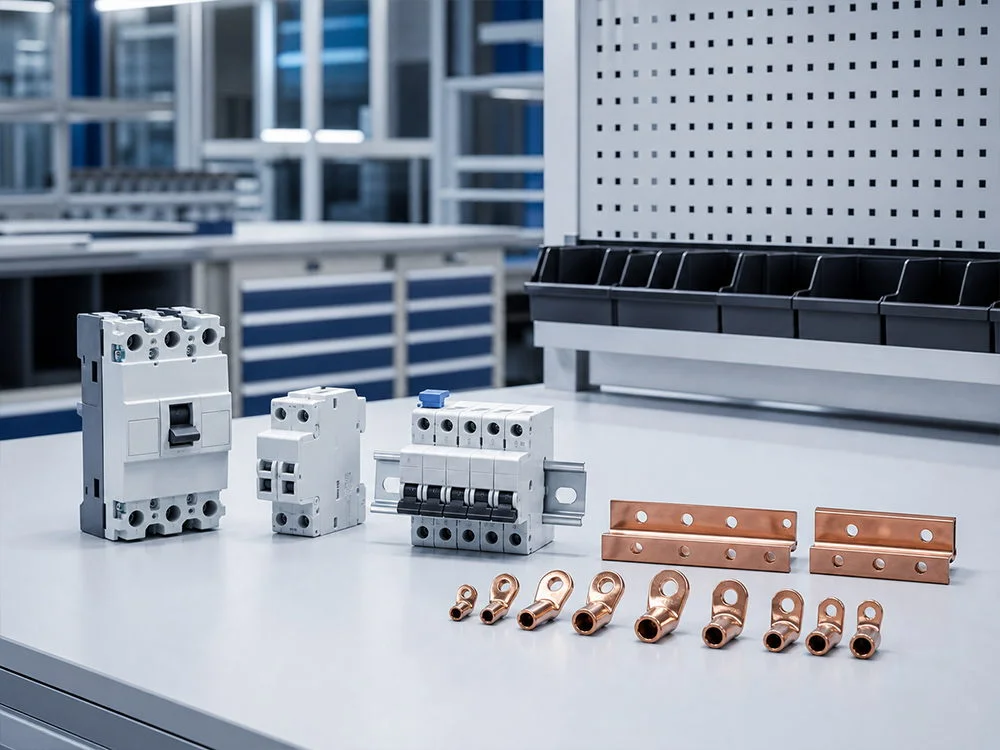
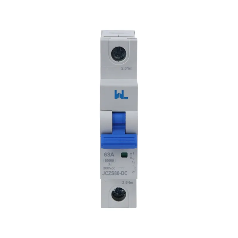
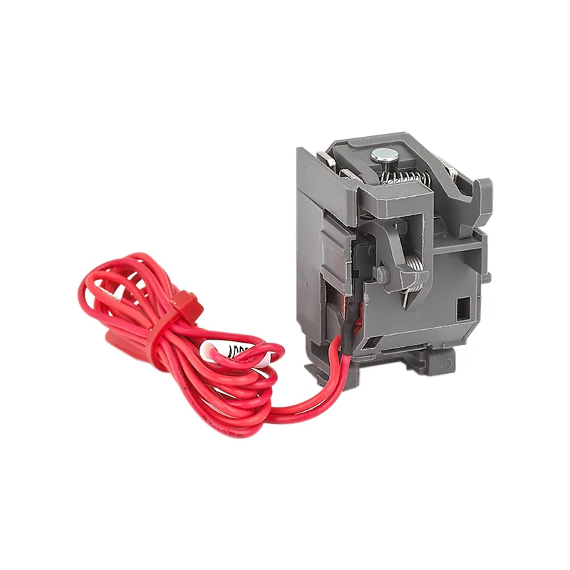
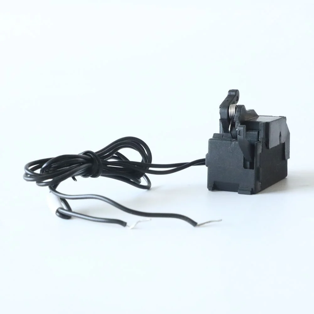
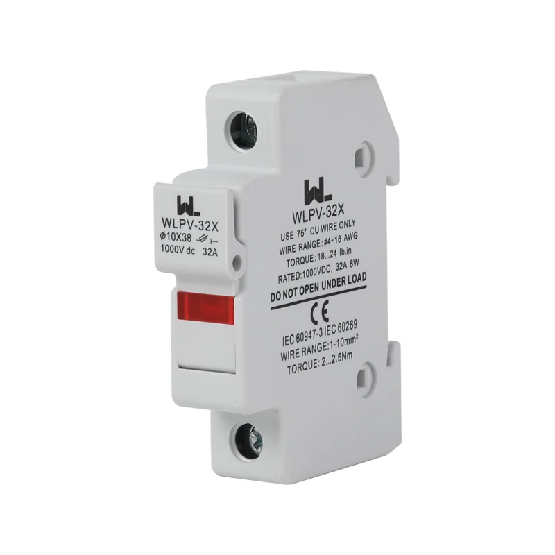
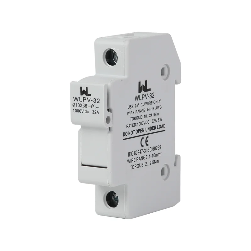
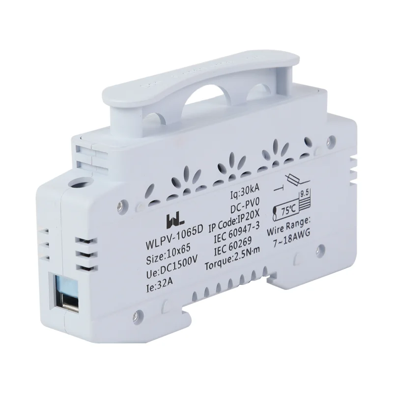
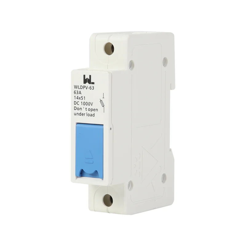
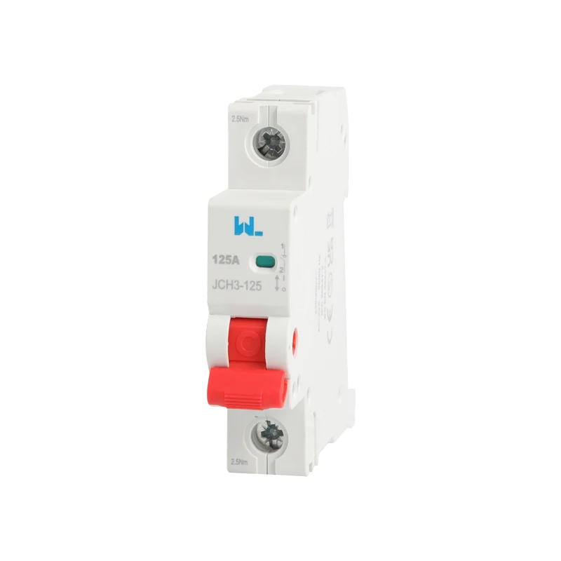
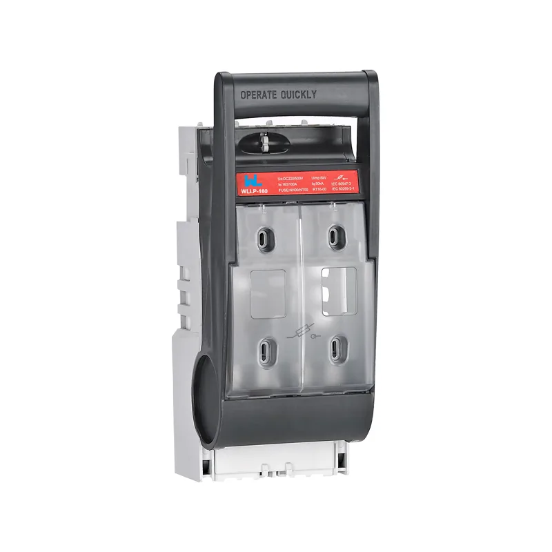
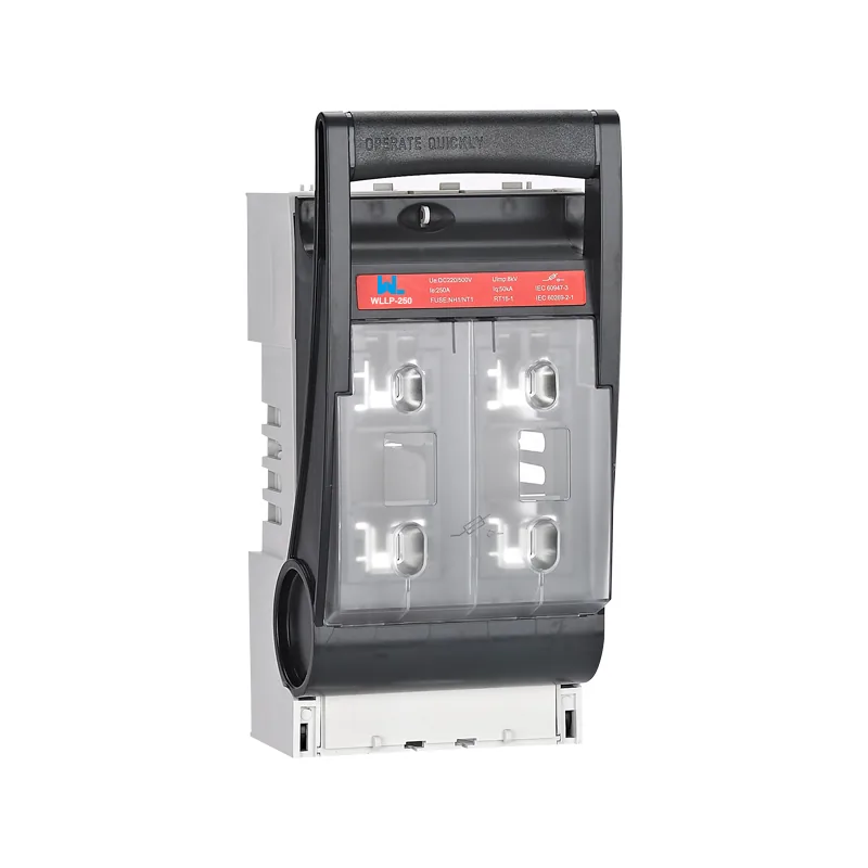
W9 Group’s circuit-protection products catalogue includes isolating-switch families such as JCH and WLLP. Use the public pages to identify a starting model, then send the one-line diagram, duty, destination standard and required documentation to the technical team. The final selection should be based on the supplied model drawing and test evidence, not a generic web image.
The public IEC catalogue for IEC 60947-3:2020 with Amendment 1:2025 covers switches, disconnectors, switch-disconnectors, fuse-combination units and dedicated accessories within its stated voltage scope. That product scope is separate from the IEC 60617 symbol vocabulary. Confirm the edition adopted or specified for the project and request the selected device’s category and conditional-rating data rather than transferring a generic standard maximum to a model.
Preguntas frecuentes
What does an isolator switch symbol look like?
It is commonly drawn as a movable blade separated from a fixed contact when open. The exact appearance varies with the drawing convention, so use the legend and device tag to confirm whether it is a disconnector, switch-disconnector or breaker. Check the schedule for poles and ratings.
Is an isolator the same as a circuit breaker?
No. An isolator provides a deliberate isolation function, while a circuit breaker also has automatic overcurrent interruption. Some combined devices perform both jobs, but the declared standard, utilization category and test data must support the claim.
Can I use a two-pole isolator on a single-phase circuit?
A two-pole device may be used to switch line and neutral where the system and local rules require or permit it. Confirm the neutral arrangement and operating sequence; a protective conductor must not be treated as an ordinary switched neutral. Use the approved earthing design and wiring diagram.
What standard defines isolator symbols?
IEC 60617 is the primary international source for graphical symbols used in electrotechnical diagrams. It defines the symbol language, not the device’s breaking capacity or installation method. IEC 60947-3 and the applicable wiring code supply the product and installation context.
Can an isolator switch be opened under load?
Only when it is explicitly rated for the load and utilization category, such as an appropriate switch-disconnector. A disconnector intended for isolation with no current should be opened after the load is stopped or interrupted elsewhere. Follow the manufacturer’s instructions and the site’s switching procedure.
Referencias
- IEC 60947-3:2020+AMD1:2025 — switches and disconnectors public scope. Alcance público y orientación verificados el 19 de octubre de 2026.
- IEC 60947-2:2024 — circuit-breaker scope distinguished from switches. Alcance público y orientación verificados el 19 de octubre de 2026.
- OSHA 1910.303 — suitability, identification and installation conditions. Alcance público y orientación verificados el 19 de octubre de 2026.
A clear isolator symbol is only the beginning: the safe circuit is the one whose source, poles, ratings and lockout boundary are unambiguous.
Review W9 Group’s isolating-switch and circuit-protection range against the approved schedule and the exact model instructions.
For a documentation review, Contáctese con el equipo with the source diagram, required switching duty and destination-market requirements.