































Basic Guide to Moulded Case Circuit Breakers
Basic Guide to Moulded Case Circuit Breakers
When Elena Ruiz, a maintenance manager in Monterrey, reset a new 400 V production feeder, the moulded case circuit breaker (MCCB) opened again before the motor reached speed. A larger replacement produced the same visible failure and delayed the line start. The reversal came from checking the load schedule, inrush current and prospective fault current together: the original selection and settings were wrong for the feeder, not evidence of a bad breaker.
Summary: An MCCB combines switching, isolation and overcurrent interruption in a moulded enclosure. For most low-voltage feeders, the correct frame, pole count, interrupting rating and trip settings matter more than a long feature list. IEC 60947-2 defines circuit-breaker characteristics and verification tests, while UL 489 is a separate North American conformity path. Start with a documented load and short-circuit study, then verify coordination, installation conditions and commissioning records before energizing.
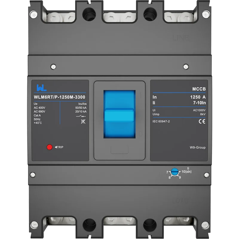
What a moulded case circuit breaker does
A moulded case circuit breaker protects a circuit when current remains above an acceptable level or rises sharply during a fault. Its insulated case contains the contacts, operating mechanism, arc-control parts and trip system. The handle provides manual switching and isolation where the installation rules permit; the trip unit opens the contacts without waiting for an operator. MCCBs are used on distribution boards, motor feeders, HVAC equipment, generators, battery systems and machine panels where the current and fault duty exceed the practical range of a miniature circuit breaker.
Terminology varies by market: “moulded” follows British usage and IEC literature, while “molded” appears in UL and North American documents. They describe the same broad product family. A breaker is not a fuse, residual-current device or arc-fault device; each protects against different hazards. Pair devices only after checking sensing, ratings and coordination.
How the protection system works
Thermal and magnetic elements
A thermal element responds to sustained overload using the heating effect of current. It allows normal, short-duration starting current but trips if conductors remain overloaded. A magnetic element responds to high current from a short circuit in a much shorter time. Time-current curves supplied by the manufacturer show the tolerance bands; the curve, rather than a single nominal number, should be compared with cable ampacity and downstream withstand.
Electronic trip units
Electronic units can provide long-time (Ir), short-time (Isd and delay), instantaneous (Ii) and, on some models, ground-fault (Ig and delay) functions. Adjustment ranges are product-specific. Reducing a dial setting does not increase the frame’s interrupting capacity, and increasing it does not permit conductors to carry more than their permitted ampacity. Record every setting on the approved one-line diagram and panel schedule.
Ratings that must agree
Specify system voltage and frequency, continuous load, number of poles, utilization category, short-circuit current and the breaker’s rated ultimate or service interrupting capacity as applicable. Check terminal temperature, enclosure ambient, altitude and derating. A 400 A frame may have several trip ranges, but the installed setting still has to protect the conductor and coordinate with upstream and downstream devices. For DC or photovoltaic circuits, use a breaker specifically marked and tested for the required polarity, voltage and interruption duty.
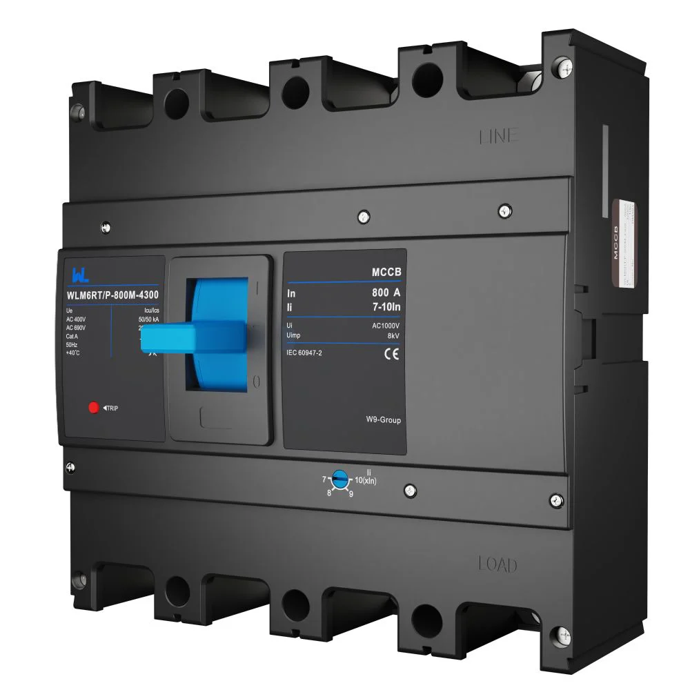
Choosing an MCCB for a real installation
Selection is a design exercise, not a catalogue-only decision. Gather the feeder length and conductor material, motor or transformer inrush, ambient temperature, enclosure type, available fault current and grounding method. Calculate voltage drop and thermal derating. Then overlay the proposed breaker curve with the protective curves of downstream devices. Selectivity may require a short-time delay, zone interlocking or a different upstream device; never add delay without checking equipment withstand and arc-flash energy.
Consider the operating pattern as well. A process line that cannot tolerate a broad outage may justify an adjustable electronic trip and alarm contacts. A small, stable feeder may be better served by a fixed thermal-magnetic unit with fewer settings to maintain. Accessories—auxiliary contacts, alarm contacts, shunt trip, undervoltage release, motor operator and communications—add wiring, testing and lifecycle cost. Specify only the functions the control system can safely use.
| Decision point | What to verify | Why it changes the result |
|---|---|---|
| Load and conductor | Continuous current, inrush, conductor ampacity, derating and voltage drop | Sets the frame and long-time pickup; prevents nuisance trips or overheated cables |
| Fault duty | Prospective short-circuit current at the installation voltage | Confirms the tested interrupting rating and enclosure withstand |
| Trip technology | Thermal-magnetic or electronic functions; permitted adjustment range | Determines coordination, testing effort and maintenance skill required |
| Poles and accessories | 2/3/4-pole arrangement, neutral switching, terminals and auxiliary devices | Must match the grounding method, panel space and control wiring |
| Environment | Ambient temperature, altitude, enclosure, humidity and contamination | Can reduce continuous current or require a different enclosure and sealing method |
Applications and lifecycle value
In commercial buildings, MCCBs protect risers, chillers and tenant distribution while providing a local isolation point. In factories, they protect motor-control centers and machine feeders where starting currents and frequent switching demand a carefully chosen curve. In renewable-energy and EV infrastructure, they can protect AC feeders or designated DC circuits, but bidirectional current, backfeed and isolation requirements must be reviewed separately. Data centers value predictable selectivity and clear trip indication because an unnecessary upstream operation can affect many racks.
The business case is lifecycle-based. A correctly coordinated breaker can limit the outage to the affected feeder, reduce troubleshooting time and preserve documented settings when loads change. Adjustable units may avoid a frame replacement, but they also require tamper control, periodic verification and trained technicians. Include engineering, injection testing, spare trip units, accessory replacement, downtime exposure and arc-flash mitigation in a total-cost review. Any payback number is illustrative until it is calculated from the project’s own outage and maintenance data.
| Application | Common MCCB value | Evidence to request before approval |
|---|---|---|
| Commercial distribution | Feeder isolation and selective clearing | One-line study, coordination plot, terminal schedule and local code review |
| Motor or HVAC feeder | Inrush tolerance with overload protection | Motor data, starting profile, trip curve and starter withstand |
| Solar, storage or EV AC feeder | Scalable protection and status indication | Backfeed analysis, voltage/frequency rating, isolation and accessory diagram |
| OEM machine panel | Repeatable protection across machine variants | Panel short-circuit rating, wiring diagram, test plan and spare strategy |
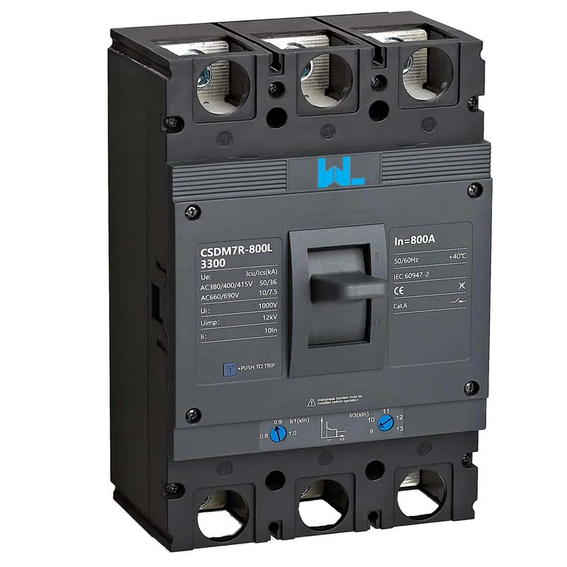
Standards, compliance and commissioning
IEC 60947-2 covers low-voltage circuit-breaker characteristics, construction and verification tests, including dielectric, temperature-rise and short-circuit performance. UL 489 covers molded-case circuit breakers, molded-case switches and circuit-breaker enclosures in the UL conformity system. NFPA 70 (the National Electrical Code) sets installation requirements in applicable U.S. jurisdictions; it is an installation code, not a product certificate. NEMA application guidance can help with selection language but does not replace a test report or certification.
Ask for the declaration or listing that applies to the destination market, tested interrupting rating at the declared voltage, terminal torque instructions, accessory wiring diagrams and routine-test records. Unsupported “certified” claims can cause rejected submittals, delayed energization, warranty disputes or regulatory action. Before handover, inspect clearances and torque, verify phase and neutral identification, perform primary- or secondary-injection tests where required by the trip-unit instructions, and preserve as-left settings and results. Re-test after a protection change or major load modification.
Procurement checklist and W9 resources
- Send the supplier a one-line diagram, load schedule, fault-current calculation, destination market and environmental conditions.
- Request the exact frame, poles, trip unit, interrupting rating, dimensions, terminals and accessory code—not a family-level brochure.
- Review time-current curves and coordination with the responsible engineer; freeze settings in a signed schedule.
- Define factory inspection, routine tests, packaging, traceability, spares and the documents required at site.
- Label the installed device and keep the datasheet, settings, test results and change owner in the maintenance record.
W9 Group’s published WLM6RT adjustable MCCB page can help teams compare frame information and accessory questions. For design context, see the guide to MCCB features and applications and the practical article on choosing a moulded-case circuit breaker. Confirm current drawings and test documentation for the exact order code before approval.
Frequently asked questions
What is a moulded case circuit breaker?
An MCCB is a low-voltage circuit breaker housed in an insulated moulded case. It provides manual switching and automatic interruption for overloads and short circuits. The frame, poles, trip unit and ratings are order-code specific.
What is the difference between an MCCB and an MCB?
MCCBs generally cover higher currents and fault levels and offer larger frames, more accessories or adjustable trip units. MCBs are compact devices commonly used on final circuits. Choose by the calculated load, fault duty, space and required functions rather than by current alone.
Should I choose a thermal-magnetic or electronic trip unit?
Thermal-magnetic units suit many stable feeders and have fewer settings. Electronic units can add adjustable long-time, short-time, instantaneous and ground-fault functions for coordination or monitoring. The safer option is the one that is correctly calculated, documented and maintained.
Can an MCCB be used on a DC or photovoltaic circuit?
Only when the breaker is specifically rated and tested for the DC voltage, polarity, current and interruption duty. AC ratings cannot be assumed to apply to DC. Review the manufacturer’s DC diagrams, isolation requirements and the system’s backfeed conditions.
How often should an MCCB be tested?
Follow the manufacturer’s instructions, site maintenance plan and applicable code or authority requirements. Visual inspection, torque checks and functional or injection tests are typically documented at commissioning and after significant changes. Shorten the interval when the environment is harsh or operation is critical.
Authoritative references
- IEC 60947-2, Low-voltage switchgear and controlgear—Circuit-breakers.
- UL 489, Molded-Case Circuit Breakers, Molded-Case Switches and Circuit-Breaker Enclosures.
- NFPA 70, National Electrical Code.
- NEMA application guidance for low-voltage moulded-case circuit breakers.
The dependable breaker is the one whose rating, settings and documentation still make sense when the plant changes. Explore W9’s circuit-protection products and contact the team with your one-line diagram, load data and destination-market requirements.