





























What Are Auxiliary Contacts for MCCBs? Functions and Standards
What Are Auxiliary Contacts for MCCBs? Functions and Standards
When a panel engineer in Rotterdam encountered a feeder that still showed “healthy” after a molded-case circuit breaker (MCCB) was opened, the engineer followed the wiring tutorial, swapped a relay, and repeated the test. The indication did not change; a shutdown review then revealed the auxiliary contact was wired to the wrong terminal and selected for a different frame. The breaker itself was sound. The failure was a selection and specification error—so what should an MCCB auxiliary contact report, and which standards make that signal dependable?
Summary: An MCCB auxiliary contact is a low-power, mechanically linked switch that remotely reports breaker ON/OFF position and, depending on accessory type, a trip event. Specify it as a control component—not a second power pole—by checking frame, contact logic, voltage, current, terminal torque, load category, and the applicable standard. Typical catalogue values are 0.3 A at AC 230/400 V and 0.15 A at DC 24/110/220 V; match those limits to the PLC, relay, or annunciator input, then prove the truth table during FAT and SAT.
What an MCCB auxiliary contact actually does
The MCCB auxiliary contact follows the breaker mechanism and changes state when the breaker handle or operating mechanism moves. A normally open (NO) or normally closed (NC) circuit can therefore tell a building-management system that a feeder is closed, isolated, or available for service. In a remote-control panel, that simple state feedback prevents a command sequence from assuming that a breaker moved when it did not.
It is useful to separate three signals that are often confused:
- Position (AX): reports ON/OFF status, including a deliberate manual opening.
- Alarm (AL): reports a protective or free-trip condition such as overload, short circuit, undervoltage, residual-current operation, or a manual trip that releases the mechanism.
- Alarm-plus-auxiliary: combines status and trip indication in one accessory assembly, subject to its contact arrangement and wiring diagram.

Ratings, contact logic, and frame fit
Selection starts with the MCCB frame, not with the control voltage alone. In one common frame-coded system, AX-125 is intended for 125/160-frame breakers, AX-250 for 250-frame breakers, and AX-400 for 400-frame breakers; the alarm family uses corresponding AL-125, AL-250, and AL-400 codes. A physically similar accessory from another frame can fail to latch, obstruct the mechanism, or leave the indication permanently false.
Next, read the electrical rating in the same units used by the control designer. The listed AX and AL characteristics are Ue AC 230 V/400 V and DC 110 V/220 V/24 V, with In 0.3 A at AC 230/400 V and 0.15 A at DC 110/220/24 V. These are modest currents. A PLC input or interposing relay is usually appropriate; switching a motor coil directly may exceed the contact’s utilization category and shorten life. Confirm whether the circuit is resistive, inductive, or electronic before finalizing suppression and fusing.
Contact notation also matters. “1 C/O” means one changeover contact, while “1 NO + 1 NC” describes two dedicated circuits. The terminal drawing determines which contact is closed when the breaker is ON, OFF, or tripped. Always prove the truth table with a continuity test during factory acceptance testing (FAT), then repeat it after installation if the accessory was field-fitted.
How to read the technical data without over-promising
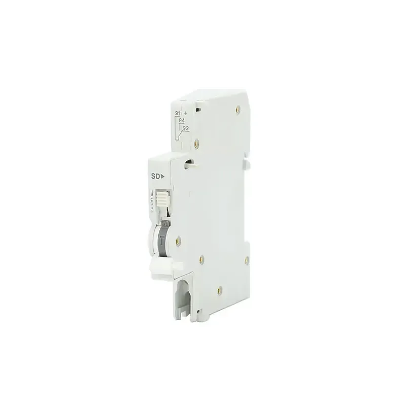
Compact DIN-rail accessories illustrate the level of detail a robust specification should contain. A representative alarm-auxiliary listing states 2 mA–100 mA at 24–240 VAC and 24–220 VDC, one C/O (1 NO + 1 NC), 0.5–2.5 mm² cable, Ui up to 500 V, and Uimp 4 kV. It also identifies a 1-pole, 9 mm DIN-rail format, IP20 protection, −25 to +70 °C operation, 1 N·m terminal torque, 6,050 electrical operations, and 10,000 mechanical operations.
Those figures are useful for panel layout and maintenance planning, but they are not a guarantee of system life in every duty. Electrical endurance depends on load type and switching frequency; mechanical endurance describes operation of the mechanism under the manufacturer’s test conditions. For a high-cycle generator or data-center transfer scheme, calculate expected operations per year and schedule inspection before the endurance number is reached.
A related compact format may specify 24–240 VAC and 24–220 VDC at 2–100 mA, one C/O, 500 V Ui, 4 kV Uimp, 1-pole 9 mm DIN-rail width, 6,050 electrical and 10,000 mechanical operations, IP20, −5 to +40 °C ambient, and 0.8 N·m terminal torque. The different ambient range and torque show why a “same footprint” assumption is unsafe.
Position feedback versus trip alarm in real applications
| Signal | What the operator sees | Typical control use | Commissioning check |
|---|---|---|---|
| Auxiliary (AX) | Breaker ON/OFF position | Interlock permissive, mimic panel, BMS status | Open and close the breaker manually; verify both states |
| Alarm (AL) | Protective or free-trip event | Trip annunciation, event log, remote alarm | Use the approved test procedure; do not infer trip from position alone |
| Alarm + auxiliary | Separate status and trip channels | Critical feeder sequencing and root-cause analysis | Test normal opening and a simulated protective trip separately |
In a data center, the distinction prevents a nuisance alarm from being hidden as a normal OFF command. In an industrial machine, it supports a safe restart permissive: the controller can require “breaker closed” while separately blocking restart after a protective trip. For an EPC project, labeling both circuits at the terminal strip reduces troubleshooting time when drawings are handed from construction to operations.

Application and environment comparison
| Application dimension | Primary risk | Specification emphasis | Practical action |
|---|---|---|---|
| Commercial distribution board | Incorrect status shown to facilities staff | AX logic, 24 VDC input compatibility, clear labels | Document NO/NC truth table in the panel schedule |
| Industrial motor feeder | Inductive switching and contact wear | Utilization category, suppression, duty cycle | Use an interposing relay when coil or inrush exceeds In |
| Data-center A/B power | False “available” signal during a trip | Separate AX and AL channels, tested interlocks | Run FAT/SAT scenarios for manual OFF and protective trip |
| Compact DIN-rail assembly | Heat, torque, or space limits | Ambient range, 9 mm width, Ui/Uimp, torque | Reserve wiring space and torque terminals to the data sheet |
Standards and compliance: what they cover
IEC 60947-5-1:2024 covers control-circuit devices and switching elements, including requirements and tests relevant to auxiliary contacts. IEC 60947-5-4 addresses methods for assessing the performance of low-voltage control-circuit contacts; it is a test and performance framework, not a blanket approval of every installation. Accessories used with residual-current circuit-breakers may also be specified against IEC/EN 61009-1, while North American projects can invoke UL 1077 supplementary protectors or other application-specific UL requirements.
Ask for the exact declaration, test report, or certificate scope for the model and configuration being purchased. A standard listed on a catalogue page does not by itself prove certification, and a component compliant in one market may still need enclosure, wiring, spacing, or national code checks in another. Unsupported “certified” language can trigger rejection at submittal, re-testing costs, shipment holds, or warranty disputes.
Procurement actions that prevent rework
- Freeze the interface: record frame code, contact arrangement, Ue, In, conductor size, and terminal torque on the approved datasheet.
- Match the signal architecture: use AX for position and AL for trip; use an interposing relay for inductive or higher-current loads.
- Check environment and endurance: compare ambient limits and IP rating with the enclosure, then estimate annual operations against 6,050 electrical and 10,000 mechanical cycles where those figures apply.
- Verify standards evidence: request model-level documents and confirm the destination-market code before you print a compliance claim.
- Witness the test: include manual opening, closing, protective-trip simulation, power loss, and PLC alarm reset in FAT/SAT records.
For buyers who need a documented source, W9 Group lists its MCCB auxiliary contact by frame and control rating, alongside an alarm contact family. Its compact JCOF auxiliary contact option can be reviewed when a DIN-rail format is preferred. Treat these listings as a starting point for the approved technical submittal, and ask for configuration-specific drawings when the project has unusual interlocks.
Frequently asked questions
What is the difference between an MCCB auxiliary contact and an alarm contact?
An MCCB auxiliary contact reports the breaker’s operating position, while an alarm contact reports a protective or free-trip event. A normal manual OFF can therefore change AX without creating the same AL signal. Wire and program them as separate meanings.
Can an auxiliary contact switch a 230 V load?
Only when the contact’s Ue and In ratings, utilization category, and load type permit it. The cited AX/AL data list 0.3 A at AC 230/400 V; a larger or inductive load should use an interposing relay and suitable suppression.
How do I choose the correct MCCB frame code?
Match the accessory code to the breaker frame: AX-125 covers 125/160 frames, AX-250 covers 250, and AX-400 covers 400; alarm codes follow Al-125/250/400. Confirm the manufacturer’s compatibility drawing before ordering.
Are IEC 60947 references proof that a product is certified?
No. The standard defines construction and test requirements; certification depends on a specific model, configuration, and recognized assessment. Request model-level evidence and verify the scope for your destination market.
What should be tested during commissioning?
Check continuity and PLC indication for ON, OFF, and protective-trip states, then verify alarm reset and interlock behavior. Record terminal torque and the final NO/NC truth table in the as-built package.
References
- IEC 60947-5-1:2024, Low-voltage switchgear and controlgear — Control circuit devices and switching elements.
- UL 1077 overview, Supplementary Protectors.
- W9 JCSD alarm auxiliary contact technical listing.
The durable lesson is simple: a tiny contact can carry a large operational consequence. Specify the signal, frame, rating, and evidence together, then prove the truth table before energizing the system. Review the full W9 protection-products range, consult technical support for drawings, or contact W9 Group when your MCCB monitoring scheme reaches the approval stage.