































Best MCCB Breaker: An Essential Guide for Electrical Safety
Best MCCB Breaker: An Essential Guide for Electrical Safety
When Priya, a facilities engineer in Rotterdam, restored power to a chilled-water plant, the new feeder breaker opened as soon as the largest pump started. The electrician checked terminations and insulation; both were sound. A review of the one-line diagram found the real problem: a fixed magnetic pickup had been selected without checking motor inrush or the upstream breaker curve. The breaker was healthy, but the selection process was not.
Summary: The best MCCB breaker is the one whose voltage, continuous-current setting, interrupting capacity and time-current curve fit the installation. For IEC projects, compare prospective fault current with Icu and service performance Ics under IEC 60947-2; North American projects use the marked interrupting rating and UL 489 framework. Gather load, fault-study and coordination data before choosing frame size, poles, trip unit and accessories.
What makes an MCCB the “best” choice?
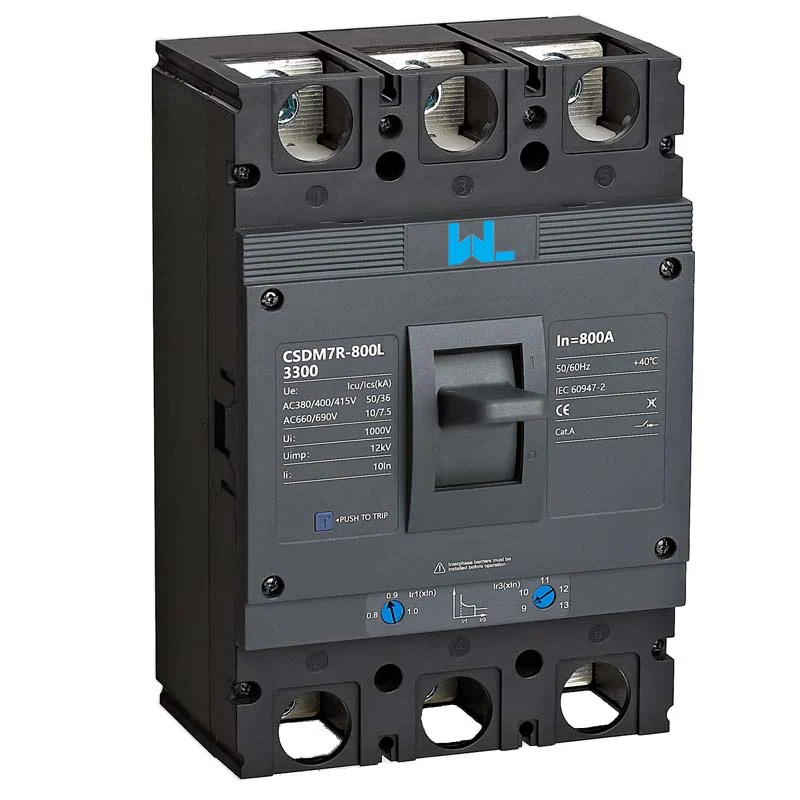
A molded-case circuit breaker (MCCB) combines contacts, arc-control parts, a trip mechanism and an insulating case. Its job is to protect conductors and equipment from overload and short circuit, and to provide isolation when the product is identified for that duty. “Best” is therefore a system decision, not a universal brand ranking. A breaker with a higher ampere number can still be wrong if its voltage, fault rating or trip curve does not match the panel.
Start with the nameplate data
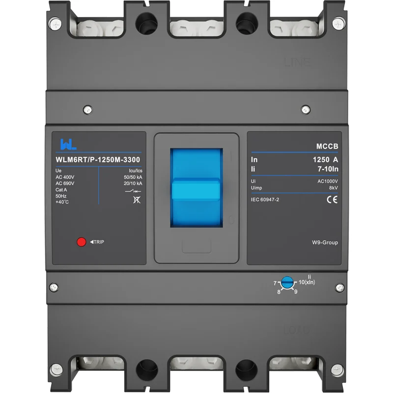
Record rated operational voltage (Ue), frequency, number of poles, frame rating and trip rating. The frame is the mechanical and thermal platform; an adjustable trip can be set below the frame rating, subject to the manufacturer’s instructions and conductor ampacity. Confirm insulation voltage, terminal kits, neutral protection and the enclosure’s ambient-temperature limits. For a three-phase, solidly grounded feeder, three poles may be suitable; a switched neutral or separately derived system can require four poles.
Trip technology and selectivity
Thermal-magnetic units use a bimetal for time-delayed overload response and a magnetic element for high-current operation. They are robust and economical, but their settings may be fixed or limited. Electronic trip units sense current and can provide long-time, short-time, instantaneous and, on some series, ground-fault functions. Adjustable pickup and delay improve selectivity only when verified against conductor ampacity and time-current curves. Every setting must be documented and protected from casual adjustment.
Ratings that protect people, plant and uptime
The prospective short-circuit current at the installation point is the first safety check. Under IEC 60947-2, Icu is ultimate short-circuit breaking capacity and Ics is service breaking capacity, expressed as a percentage of Icu in the manufacturer’s declaration. If a calculation shows 35 kA available at 400 V, a breaker declared for only 25 kA is unsuitable, even if its continuous-current rating is correct. Where short-time delay is used, also verify rated short-time withstand current (Icw).
For UL 489 installations, use the marked interrupting rating, series-combination information and panel listing requirements accepted for that specific equipment. IEC values and UL markings are not interchangeable. A short-circuit study should account for transformer impedance, utility contribution, motor contribution and conductor length; ask the manufacturer for certified test data or declarations rather than copying a value from another frame.
Match the breaker to the application
Application duty changes what “best” means. A pump feeder must ride through starting current; a photovoltaic (PV) feeder needs the correct DC polarity and voltage; a data-center busway prioritizes selective coordination and maintenance visibility. The following checks are design prompts, not default settings.
- Motors and compressors: Plot the breaker curve with motor full-load current, locked-rotor current and the overload relay. Set instantaneous or short-time functions high enough for permitted starting, while retaining short-circuit protection. Follow the motor-starter and local installation-code requirements.
- Transformers: Energisation inrush is brief and asymmetric. Use transformer manufacturer data and a time-current plot; a low magnetic pickup can trip during energisation. Recalculate secondary fault duty after impedance and feeder length are known.
- PV and battery systems: DC arcs and bidirectional current require a breaker specifically rated for the circuit’s DC voltage, polarity and configuration. Coordinate with combiner, inverter and isolation equipment; do not substitute an AC-only MCCB.
- Data centers: Availability favors selective coordination, alarm contacts, shunt trips and status or communications accessories. Electronic trip units add flexibility but require control power, commissioning and periodic verification.
- OEM and industrial panels: Standardizing a frame family can simplify spares and training. Check mounting dimensions, lug options, creepage, clearance and accessory wiring before approving a substitute.
Compare configurations before purchase
Use a feature comparison rather than a catalogue headline. A lower initial price can be outweighed by engineering hours, nuisance trips, spare inventory or an outage during replacement.
| Decision dimension | Fixed thermal-magnetic MCCB | Adjustable electronic MCCB | Lifecycle implication |
|---|---|---|---|
| Overload response | Thermal delay; limited adjustment | Programmable long-time pickup and delay | Electronic setup adds commissioning work |
| Short-circuit functions | Magnetic instantaneous element | Short-time, instantaneous and optional ground fault | More coordination options; settings need records |
| Changing loads | Best where duty is stable and known | Useful for variable feeders after a study | Flexibility can reduce nuisance outages |
| Accessories | Auxiliary, alarm and shunt options vary | May add metering or communications | Reserve panel space and control power |
| Maintenance | Simple visual and mechanical checks | Functional trip testing and firmware/configuration control may apply | Budget calibrated testing and training |
Application-to-feature map
| Application | Main risk | Evidence to request |
|---|---|---|
| Motor feeder | Starting current and overload | Motor data, time-current curves and coordination plot |
| Transformer secondary | Inrush and available fault current | Transformer impedance, Icu/ |
| PV combiner or inverter | DC arc and reverse contribution | DC rating, polarity, isolation instructions |
| Data-center busway | Availability and maintenance | Selective-coordination study, alarm and test provisions |
Selection, installation and total-cost checks
Illustrative calculation (not a design value): A balanced 75 kW, 400 V, three-phase motor at power factor 0.85 and efficiency 0.92 has running current of about 139 A [75,000 ÷ (√3 × 400 × 0.85 × 0.92)]. A designer might investigate a 250 A frame with a 160 A setting, then verify cable ampacity, derating, starting current and curves. The arithmetic estimates running current only; it does not choose the breaker.
- Capture voltage, frequency, earthing arrangement, continuous and peak load, ambient temperature and inrush.
- Calculate prospective fault current at the breaker and specify IEC Icu/
- Select frame, trip range, poles, neutral treatment and accessories; verify dimensions, terminals and enclosure clearances.
- Complete time-current coordination and arc-energy reviews with upstream and downstream devices; lock and record final settings.
- Plan commissioning, inspection, calibrated trip testing, spares and end-of-life replacement. Include curves, torque values and test records in handover documents.
Lifecycle cost includes design review, testing, spare breakers, lost production and safe access—not only unit price. During installation, verify conductor preparation, lug compatibility, phase identification, torque and clearances. De-energize and prove dead before maintenance; follow the product instructions and local safe-work rules.
Standards and compliance
IEC 60947-2 covers low-voltage circuit-breakers and the associated test methods and declarations. UL 489 covers molded-case circuit breakers and enclosures for its certification market. NFPA 70 (National Electrical Code) is a United States installation code addressing conductors, overcurrent protection, disconnects and working space; it is not a product certification. Destination market, intended use and marketing claims determine which route applies.
Request the applicable declaration, certificate or listing for the exact series and accessories. A test method or code reference does not automatically prove certification. Unsupported claims can delay approval, invalidate a panel listing, create rework and expose the project to safety and liability risk.
Zhejiang W9 Group Technology Co., Ltd. supplies low-voltage protection products and can discuss OEM/ODM configurations, testing coordination and documentation. Share the duty, fault study, destination standard and panel constraints so a proposed MCCB can be assessed on evidence. Our MCCB features and applications guide provides additional engineering context, while the MCCB selection guide helps structure a procurement review.
Frequently asked questions
What is the best MCCB breaker for a 400 V motor?
There is no universal model. Select a breaker with the required 400 V rating, fault capacity and a curve coordinated with motor inrush and the overload relay. Confirm cable ampacity, enclosure conditions and local code before final approval.
How do I choose MCCB ampere rating?
Start with calculated continuous load and conductor ampacity, then account for ambient derating and starting or cyclic duty. Choose a frame and trip setting that protect the conductor; never use a larger rating simply to stop nuisance trips.
Are Icu and Ics the same as a UL interrupting rating?
No. Icu and Ics are IEC 60947-2 declarations, while UL 489 uses its own marked rating and test framework. Use the standard required for the destination market and do not convert values without engineering justification.
When is an electronic trip unit worth the cost?
It is useful when selective coordination, changing loads, ground-fault protection or metering requires adjustable functions. The extra flexibility brings setup, control-power and testing responsibilities, so include those costs in the business case.
Can an AC MCCB protect a photovoltaic DC circuit?
Only if the breaker is specifically rated for the circuit’s DC voltage, polarity, interruption duty and configuration. AC and DC arc behavior differ; follow the breaker and inverter manufacturers’ instructions and the applicable PV installation requirements.
What maintenance does an MCCB need?
Follow the series instructions for visual inspection, mechanical operation, torque checks, thermal scanning and functional trip testing. Frequency depends on duty and environment; keep calibrated records and isolate the circuit safely before work.
Authoritative references
- IEC 60947-2: Low-voltage switchgear and controlgear — Circuit-breakers, International Electrotechnical Commission.
- UL 489: Molded-Case Circuit Breakers and Circuit-Breaker Enclosures, UL Standards.
- NFPA 70, National Electrical Code, National Fire Protection Association.
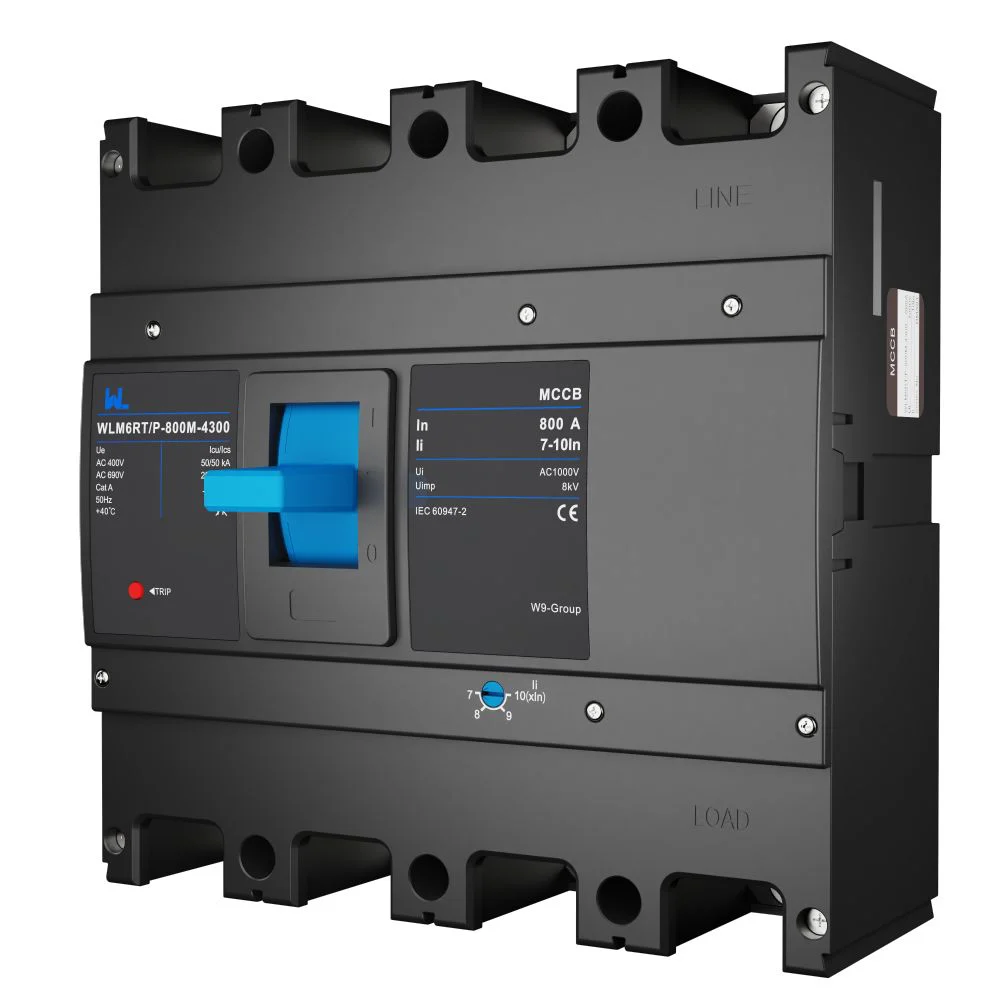
The best MCCB breaker is the one that fits the system’s fault level, trip curve and installation record—not merely the largest ampere number. For documented low-voltage protection options, visit our circuit-protection products category and contact the W9 team with your load schedule and fault study.