



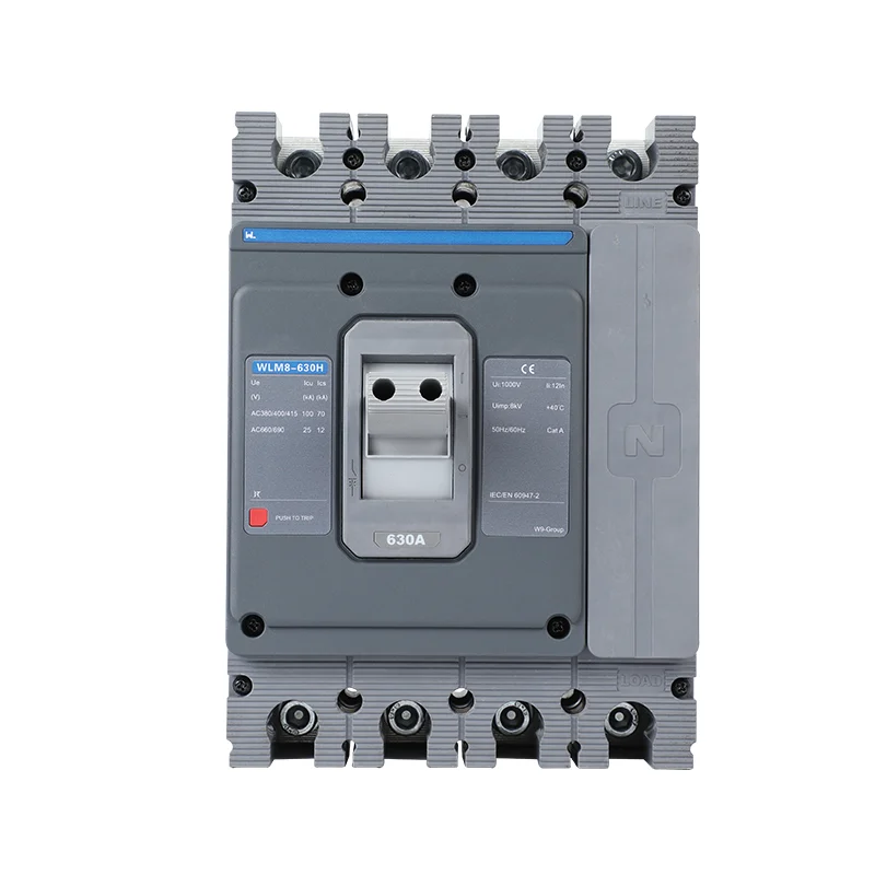
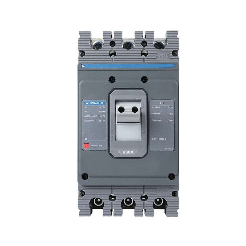
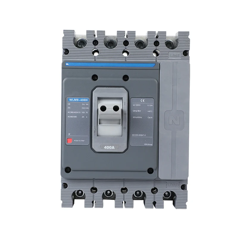
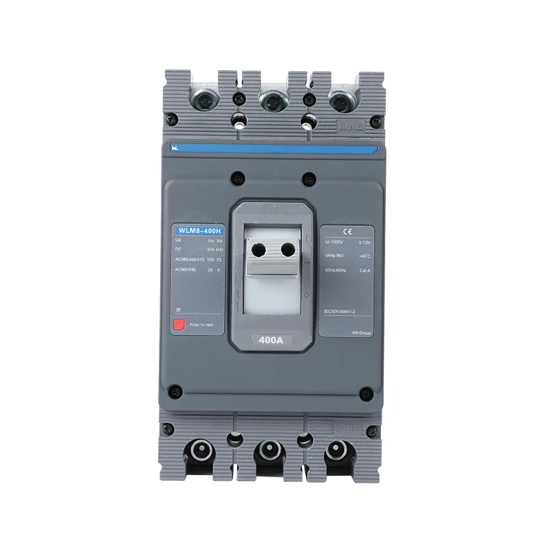
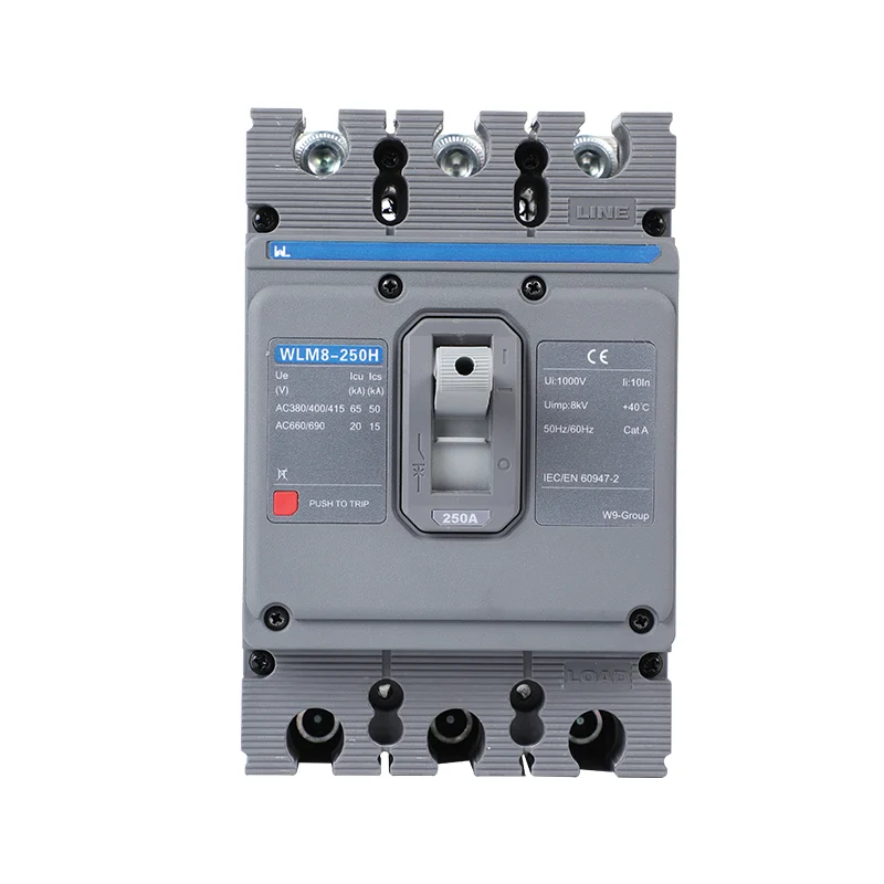
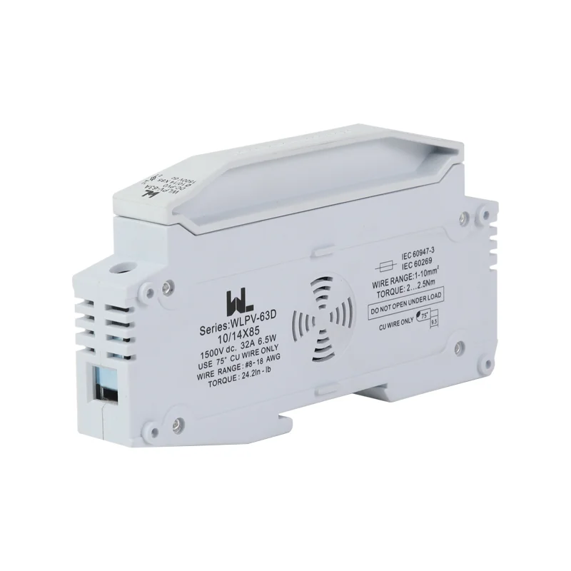
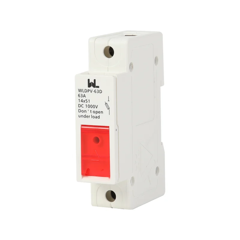
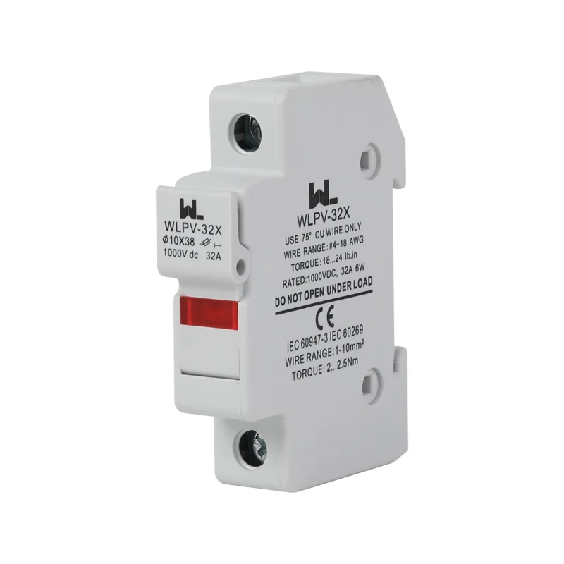
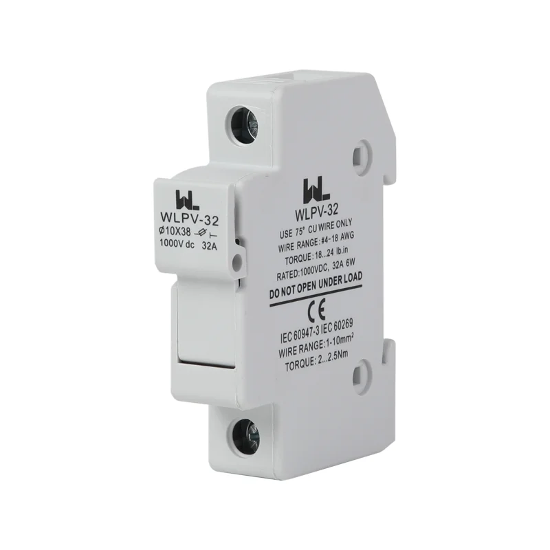
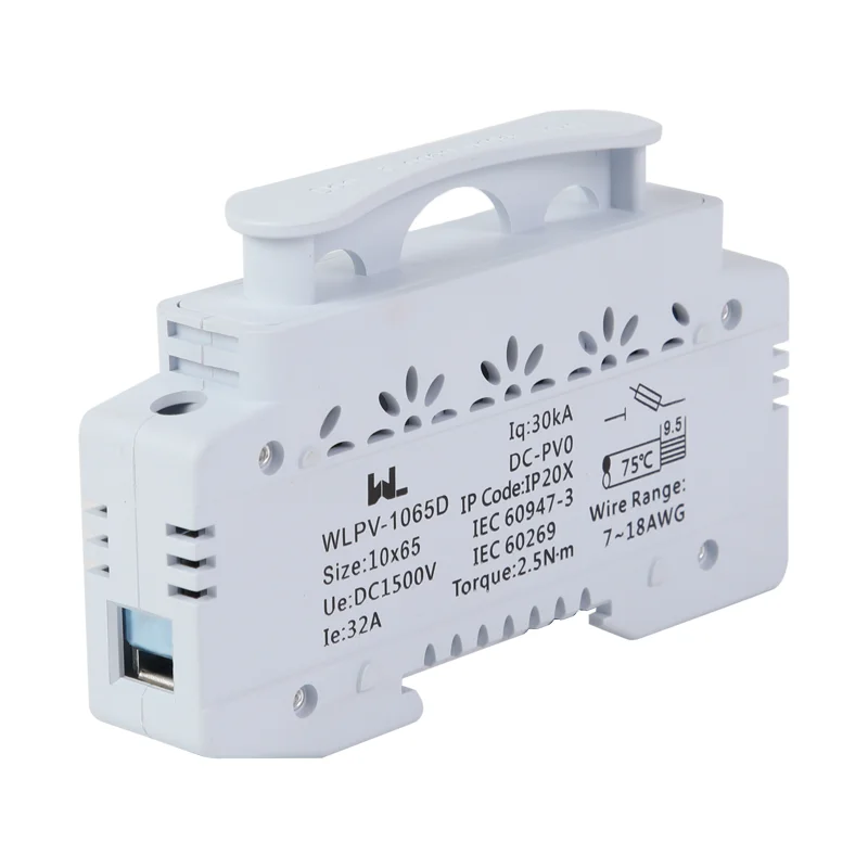
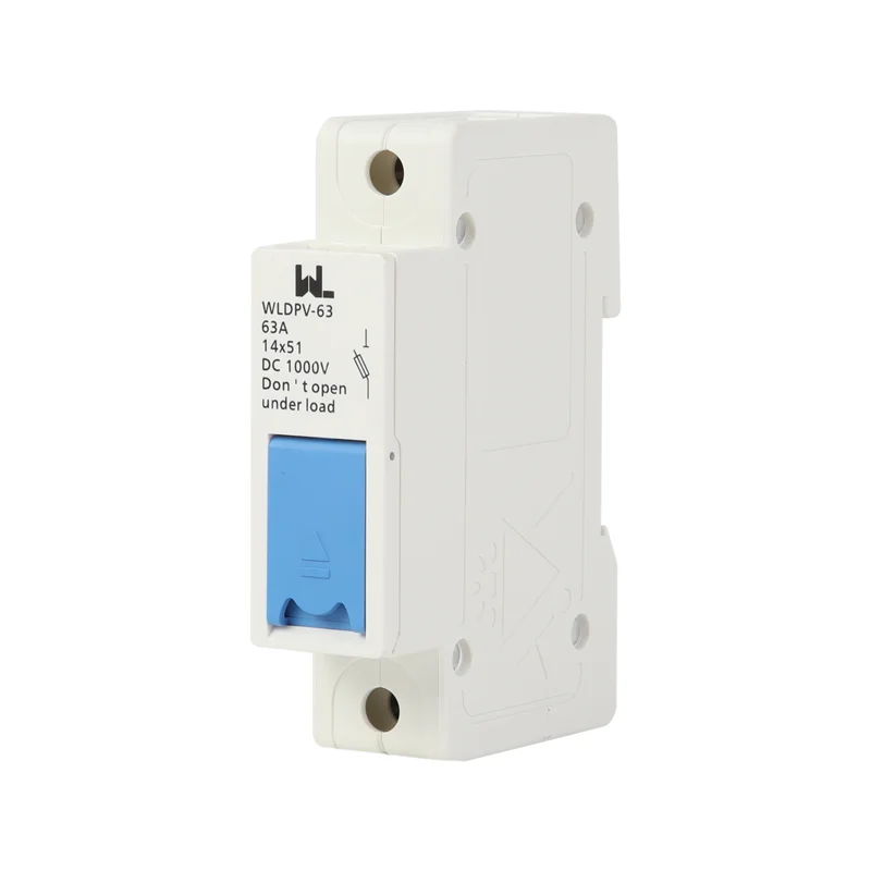
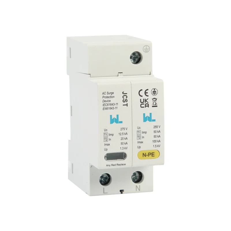
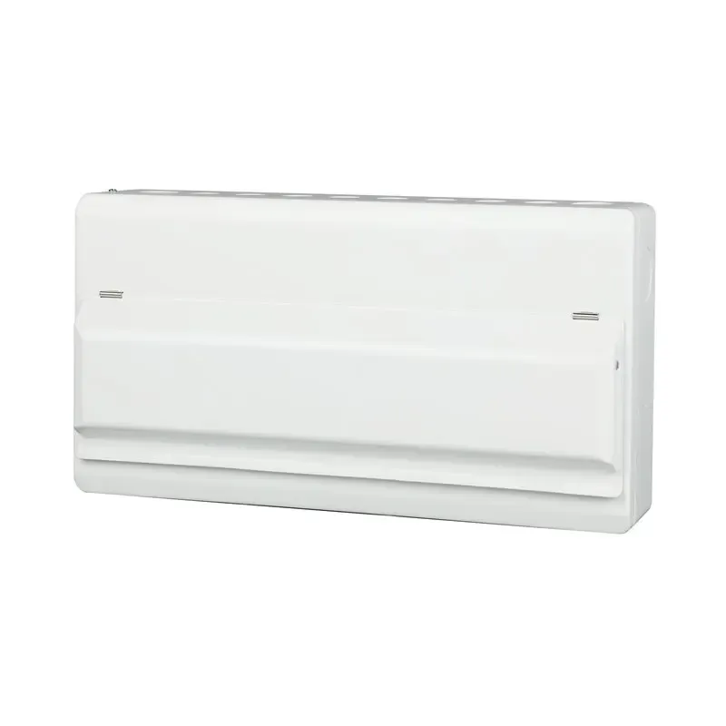





JCB3-63DC DC MCB: 태양광 응용 분야의 극성 확인
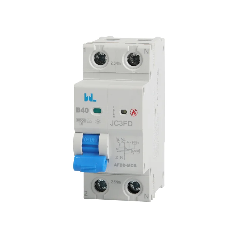
A non-polarity claim can simplify one selection question only when it applies to the exact supplied DC breaker. The current JCB3-63DC public listing contains inconsistent polarity descriptions, so unrestricted current direction must not be assumed from this article’s older title.
The table lists 6–63 A options, B/C curves, one through four poles and pole-dependent voltage values. Confirm the delivered code, markings and diagram before using any of those values for an installation.
검토하기 photovoltaic protection range against the maximum DC voltage and permitted pole connection.
Polarity is a documented operating condition
Ask W9 to resolve the polarity wording in writing for the offered version. The approved diagram must cover the source, earth arrangement and possible fault-current directions. An ordinary pole arrangement cannot be improvised to achieve a higher DC voltage.
Normal load flow and fault-current flow may differ, especially with multiple strings, batteries or bidirectional converters. A declared non-polarity capability would still not establish every source topology or series-pole connection.
The DC MCCB guide explains why an AC rating cannot establish DC interruption capability.
Evaluate DC interruption separately from AC
DC arcs do not benefit from the periodic current zero of AC. Use DC fault duty at the actual voltage and the manufacturer’s specified connection. Do not treat an AC breaking rating as a DC rating.
| 질문 | Required answer |
|---|---|
| Which version is supplied? | Exact code and terminal markings |
| Which voltage applies? | Model and pole-dependent rating |
| Which direction is permitted? | Approved polarity statement and diagram |
| What fault can occur? | Source and prospective DC fault data |
The photovoltaic distribution guide distinguishes PV-string assumptions from battery fault-current duties.

PV and battery applications need separate checks
A PV application uses array voltage, string and parallel contributions and the inverter arrangement. A battery application includes its own available 과부하 전류 and stored-energy characteristics. A broad solar-safety description does not approve both.
| Circuit | Input to the selection |
|---|---|
| PV string or combiner | Maximum voltage, parallel contributions and isolation arrangement |
| Battery feeder | Fault current, energy and direction |
| DC load circuit | Load transients, conductors and source limits |
Procurement and commissioning
Retain the exact polarity clarification and installation instructions with the order. Check delivered markings before installation and follow a competent person’s isolation and test procedure. IEC 60947-2 context does not remove the need for this model-level evidence.
자주 묻는 질문
Has unrestricted non-polarity operation been confirmed here?
No. The current public wording is inconsistent. Request the exact supplied version’s statement and terminal diagram.
Does non-polarity mean any pole connection is allowed?
No. Even a non-polarity design has specified connection, voltage and installation limits. Follow the approved diagram.
Can a PV rating be applied to a battery circuit?
Only with explicit evidence for the actual battery fault duty and connection. A PV label alone is insufficient.
What should be checked on delivery?
Check the full model code, current, poles, voltage and terminal markings against the approved documents. Resolve any inconsistency before installation.
참고문헌
- IEC 60947-2:2024 — 회로 차단기 제품 범위.
- IEC 60364-7-712:2025 — photovoltaic electrical installations.
- IEC 60947-3 consolidated edition — switches, disconnectors and switch-disconnectors.
For a PV or DC selection, W9 그룹에 문의하기 with maximum voltage, operating and fault current, earthing and the intended pole connection.