






태양광 및 배터리 저장용 DC MCCB: 크기 조정, 폴, 중단 용량
배터리 저장 장치를 추가하면 기존의 태양광 직류 분전반은 다른 유형의 보호 문제로 이어질 수 있습니다. 정격 버스 전압은 변하지 않을 수 있지만, 가용 고장 전류, 전류 방향 및 운전 특성은 크게 달라질 수 있습니다. 암페어 등급 표시가 충분해 보인다는 이유만으로 기존 차단기를 재사용하는 것은 검토에서 가장 중요한 부분인 전원 측 용량을 간과하게 만듭니다.
빠른 답변: DC MCCB 정격 선정 전압, 연속 전류, 케이블 보호, 고장 차단 및 승인된 기둥 배치에 대해 별도의 검토가 필요합니다. PV 시스템과 배터리 시스템은 동일한 버스 전압에서도 서로 다른 고장 조건을 유발할 수 있습니다. 먼저 소스별 데이터와 계통 분석 결과를 바탕으로 하고, 그 후 제조업체가 명시한 성능 범위 내에서 트립 유닛과 설치 구성 방식을 선택하십시오. 해당되는 경우, 의도된 직류 전압 하에서 Icu 및 Ics 값을 확인하고, 명시된 회로 조건도 포함해야 합니다. 태양광 인증 라벨만으로 배터리 적합성을 추론하거나 DC 표시만으로 양방향 작동을 가정해서는 안 됩니다. 전류 정격 선정은 반드시 필요하지만, 그것만으로는 차단 성능을 확립할 수 없습니다.
원천 및 고장 분석부터 시작하십시오.
PV 전원은 모듈 및 어레이의 특성에 의해 결정됩니다. 병렬 스트링은 고장 경로로 역전류를 유입시킬 수 있으며, 인버터 및 기타 연결된 장비도 해석에 영향을 미칠 수 있습니다. 배터리의 고장 거동은 화학 조성, 상태, 내부 임피던스, 구성 방식, 제조사 제공 데이터와 외부 회로에 따라 달라집니다. 이러한 정보를 일반적인 전류 배수 계수로 대체하지 마십시오.
보호 구간에 전력을 공급할 수 있는 모든 전원을 식별하십시오. 하이브리드 시스템에는 태양광 발전(PV), 배터리, 컨버터 및 커패시터가 포함될 수 있으며, 여러 가지 운전 상태가 존재할 수 있습니다. 정상 운전, 충전, 방전 및 유지보수 시 각각 어떤 장치들이 연결되는지 명시하십시오. 예상 고장 전류는 다른 버스에서의 관련 없는 값이 아니라 해당 상태와 위치를 반영해야 합니다.
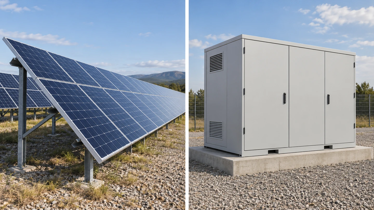
단순화된 직류 유도 회로의 경우, L/R는 전류의 시간적 거동과 관련된 시정수를 나타냅니다. 실제 시험 조건을 제조사가 명시한 차단 조건과 비교하십시오. 적용 조건이 명시되지 않은 단락전류 값은 승인 기준으로 적절하지 않을 수 있습니다. 모든 태양광 발전 어레이 또는 모든 배터리 랙에 동일한 시정수를 부여해서는 안 됩니다.
The MCCB 사양 안내서 이는 전압, 전류 및 차단용량에 대해 별도의 증거가 필요한 이유를 설명합니다. 저장 프로젝트의 경우, 동일한 기준이 적용되며, 이는 설계된 사용 조건을 충족하지 않는 조건에서 시험된 직류 값에도 마찬가지로 적용됩니다.
| 입력 | PV 평가 | Battery-storage assessment |
|---|---|---|
| Maximum voltage | Cold array open-circuit voltage and design method | Maximum battery or DC-bus voltage in relevant states |
| Operating current | Array current and required design factors | Charge/discharge duty and minimum operating voltage |
| Fault source | Parallel strings and relevant equipment contributions | Battery data plus network and converter contributions |
| Direction | Normal and possible reverse-current paths | Charge, discharge and fault-current directions |
| Interruption evidence | Declared PV duty and configuration | Declared battery/DC duty and matching conditions |
Size current without losing the protection boundary
Determine the design current from the actual duty. For a power-controlled converter, a simple P/V calculation may help establish one operating point, but efficiency, minimum voltage, overload capability and continuous-duty requirements can alter the result. A battery operating over a voltage range can draw more current at the low-voltage end for the same power transfer.
Illustrative arithmetic only: 100 kW divided by 800 V is 125 A before losses and other design allowances. This is not a recommended breaker size. It omits the voltage range, converter limits, cable conditions and project factors. Use such arithmetic to check inputs, then apply the equipment instructions and adopted installation method.
Separate the MCCB frame designation, fitted current rating and adjustable trip settings. A frame can support several versions, but the supplied trip unit determines the available functions and adjustment range. Settings must coordinate with the conductors and connected equipment. Turning a setting upward to avoid an operational trip can remove the intended overload boundary.
Thermal derating connects the catalog rating to the real enclosure. Internal temperature, adjacent loaded devices, ventilation, altitude where relevant, terminal arrangement and conductor installation can affect the permitted duty. Obtain the manufacturer’s installation guidance and the assembly designer’s thermal assessment instead of assuming the open-air catalog condition applies inside a compact cabinet.
Verify interruption and trip performance
DC interrupting capacity must cover the prospective fault duty at the actual operational voltage and approved pole configuration. For IEC-rated MCCBs, Icu and Ics have distinct test meanings. Review the applicable values and the expected service condition after interruption. A larger frame or higher current rating does not automatically supply a higher breaking capacity.
The trip characteristic must also detect and clear the faults the design expects it to address. High interrupting capacity says what the device can break under specified conditions; it does not prove that every possible low-level fault will cause operation within the required time. Coordinate overload, instantaneous or other available functions with the cable and equipment limits.
Battery-management or converter controls may limit current or command shutdown, but their role in the protection design needs documented analysis. A control function is not automatically a substitute for the required fault-interrupting device. Establish what happens if communications, auxiliary power or the control function is unavailable in a relevant fault condition.
Review selectivity and any backup protection using manufacturer data for the exact devices. An upstream and downstream MCCB do not become selective simply because their ampere ratings differ. The study should state which device is intended to operate and what loss of service is acceptable. Retain the coordination evidence with the settings schedule.
Confirm poles and the ordered configuration
Series-pole arrangements, polarity restrictions and earthing must follow the device manufacturer’s drawing. Do not divide the bus voltage by the number of visible poles to justify a connection. A link kit, terminal accessory or permitted supply direction can be part of the rated arrangement. Substituting one of those items may require renewed approval.
IEC 60947-2 is a relevant circuit-breaker standard; IEC 60947-3 addresses relevant switch and disconnector functions. Neither a family standard reference nor a storage application label establishes the complete project’s acceptance. Identify the destination-market requirements, assembly responsibilities and necessary test evidence before comparing certification claims.
| Release check | Required record | Question if missing |
|---|---|---|
| Source duty | Voltage range, fault study and operating states | Which source condition was used? |
| Current and cable | Design calculation, derating and trip settings | What protects the conductor in this enclosure? |
| Interruption | Voltage-specific capacity and declared conditions | Does the evidence cover this DC duty? |
| 연결 | Poles, links, earthing and direction drawing | Is this the exact offered configuration? |
| 시운전 | Inspection, settings, appropriate tests and handover | Who releases the assembled system? |
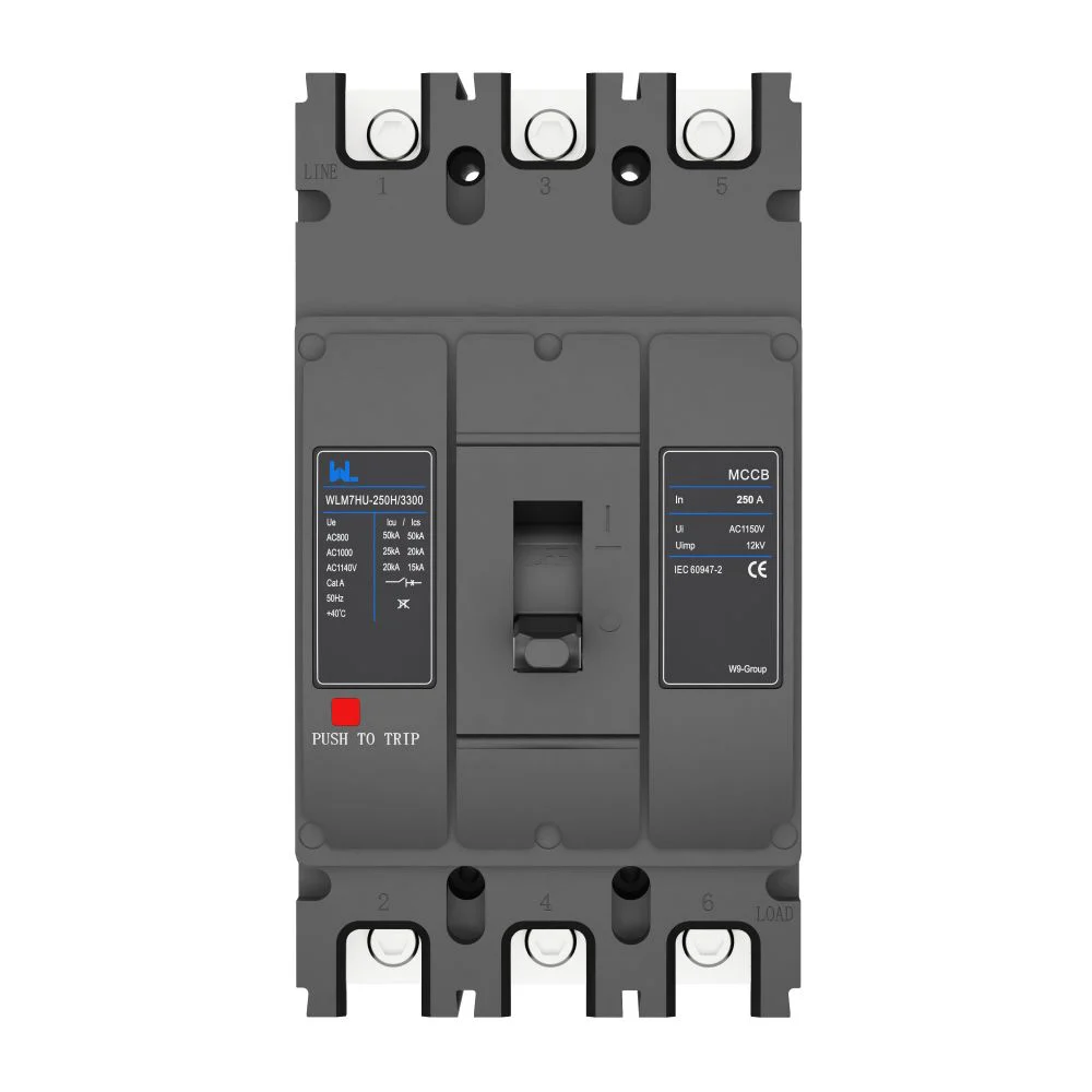
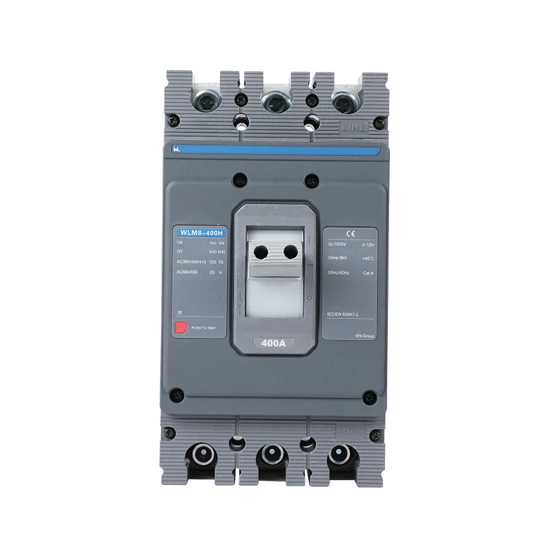
W9’s WLM7DC-400 PV DC product page supports a model-specific enquiry. Its PV designation alone does not establish battery or bidirectional suitability. Provide the storage duty and ask for an explicit confirmation supported by matching documents, rather than carrying a PV approval into a new source application.
For total project cost, compare device supply, approved links and terminals, cabinet changes, engineering, testing and maintenance access. No fixed saving follows from a particular frame size. Use the W9 product directory to identify candidates, then compare only offers that satisfy the same documented duty and scope.
자주 묻는 질문
Where can I find a DC molded-case circuit breaker manual?
Request the current manufacturer manual for the full order code. It should match the voltage, trip unit, connection and accessories being offered.
Where can I find a DC molded-case circuit breaker catalog?
Use the manufacturer catalog for initial selection, then obtain model-specific application evidence. A family overview is insufficient for battery fault-duty or reverse-current approval.
What is a DC circuit breaker?
It is a circuit breaker with declared capability to interrupt direct current under stated conditions. Its ratings must match the source, voltage and connection used in the installation.
DC 차단기는 AC 차단기와 다릅니까?
Yes. Steady DC lacks the periodic natural current zero of AC, so a separate documented DC interruption capability is required.
Can a PV MCCB be used for battery storage?
Only when its declared application envelope covers the battery duty. Confirm source fault conditions, direction, voltage, trip behaviour and the exact connection before accepting it.
Is breaker current rating enough to size a storage circuit?
No. Voltage, fault capacity, cable protection, installation derating, poles and operating direction all require separate checks. Current arithmetic is only part of the selection.
참고문헌
- 이튼: DC 및 PVGard 몰드 케이스 차단기, 신청 개요, 2026년 10월 17일에 접속되었습니다.
- ABB: SACE Tmax PV for Photovoltaic Applications, rating tables and declared configurations, accessed 17 October 2026.
- ABB: Higher-Voltage Solar Power Plant Breakers, 2018년 6월 20일, 2026년 10월 17일에 접속된 자료.
Treat source duty as a selection input
A reliable selection connects the source-specific fault study to the exact breaker, trip unit and installed configuration. Keep voltage, current and interruption checks separate long enough to verify each one, then bring them together in a single approved schedule. Reopen that schedule when storage is added, operating direction changes or the converter is replaced. For a technical enquiry, send the source data, voltage range, duty cycle and fault assumptions through the W9 그룹 연락처 페이지. Request a configuration-specific response and the matching documents before ordering. The final decision should remain with the responsible project designer, who can assess the complete system rather than one device’s headline current marking.