






























Understanding the Advantages of Air Circuit Breakers (ACBs) in Electrical Protection

Understanding the Advantages of Air Circuit Breakers (ACBs) in Electrical Protection
When a switchboard designer in Shanghai encountered an unexpected feeder trip during a hypothetical factory expansion, she replaced the breaker she suspected; the next high-load test produced the same outage. A coordination review showed the cause was selection, protection settings, and available fault duty—not merely a bad product.
Summary: An air circuit breaker (ACB) can offer stronger serviceability, adjustable electronic protection, and coordination flexibility in low-voltage switchgear, but only within its declared ratings and the installation design. Buyers should compare the three short-circuit terms—Icu, Ics, and Icw—against a verified study, then request model-level test and configuration evidence before deciding between an ACB and an MCCB. IEC 60947-2 provides the product-standard framework; it does not replace the installation requirements that apply to the project.
ACBs are generally used in low-voltage switchgear where a main, tie, or large feeder needs a maintainable protection path. Their advantages are practical, not a universal rank above molded-case circuit breakers (MCCBs). Selection depends on the fault study, duty, selectivity objective, enclosure, maintenance approach, jurisdiction, and exact product construction.
Why an ACB can improve protection design
Fault-duty capability must be read as three different questions
For an IEC-oriented specification, Icu is the rated ultimate short-circuit breaking capacity: the declared interruption capability under the prescribed test conditions. Ics is the rated service short-circuit breaking capacity, expressed as a percentage of Icu in the standard’s framework and relevant to expected post-interruption service. Icw is the rated short-time withstand current, which matters when a breaker is expected to remain closed briefly so a downstream protective device can clear a fault. These are distinct declared values; none should be inferred from frame size or a sales description.
This distinction lets an upstream device be evaluated for both interruption and short-time coordination duty. It does not prove the busbar, enclosure, cable, grounding, or arc-energy design is adequate. IEC 60947-2 defines product performance and tests; the power-system study and installation design establish assembly suitability.
Electronic protection can make selectivity more controllable
Many ACB configurations use electronic trip units with adjustable long-time, short-time, instantaneous, and ground-fault functions where the exact model provides them. This can help coordinate two or more protective devices, preserving healthy sections while a nearer device addresses a fault. Settings still require an engineer’s study, manufacturer curves, and commissioning records; a dial setting alone is not selectivity evidence.
For context on choosing the wider breaker family, see this guide to circuit-breaker functions and types. The key is to specify the protection objective first, then verify the available curves, tolerances, and tested coordination documentation against IEC 60947-2 or the applicable product basis.
Serviceability is an operational advantage, not a maintenance-free promise
ACBs are commonly available in fixed and drawout constructions. A fixed arrangement can suit a stable, space-conscious design; a drawout arrangement can let trained teams isolate, rack out, inspect, test, or exchange the breaker while retaining the switchboard interface. That can simplify planned maintenance and fault investigation when interlocks, shutters, racking, isolation, and safe-work procedures are documented and followed.
An inspectable path turns maintenance into evidence collection: review contact condition, mechanism operation, trip indication, connections, accessories, and test results at intervals set by the manufacturer and site duty. It does not replace de-energization practices, qualified personnel, or the electrical-safety program. NFPA 70 governs installation requirements in its adopted US context; other jurisdictions use their own rules.
For a companion explanation of configurations, see air circuit breaker types and applications. Ask whether the configuration is fixed or drawout, what accessories are included, and which inspection instructions apply.
ACB versus MCCB: compare the duty and operating model
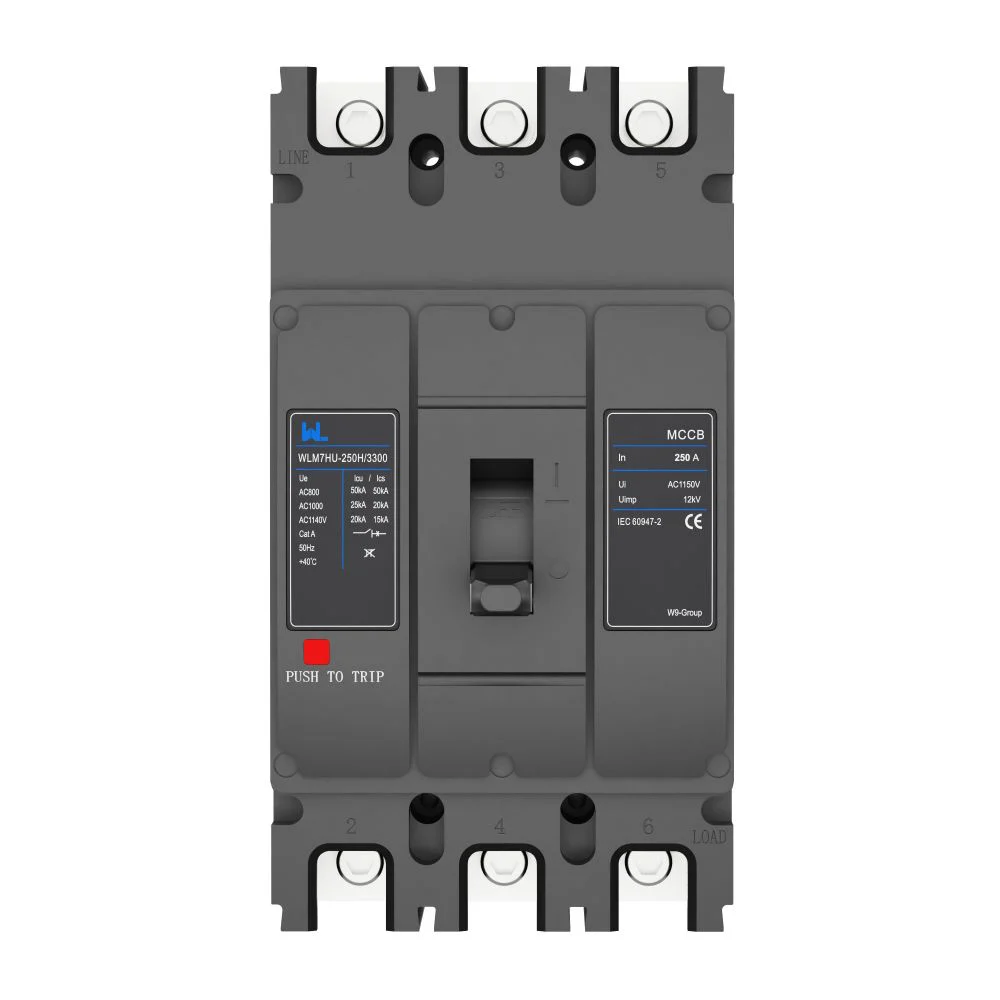
An MCCB can be proportionate where duty, coordination, footprint, and maintenance needs are modest. An ACB can suit larger low-voltage distribution schemes where maintainability and adjustable protection justify engineering and space demands. Exact ratings, trip unit, enclosure, and test data decide.
| Dimension | ACB tendency | MCCB tendency | Evidence to request |
|---|---|---|---|
| Typical scope | Main, tie, or significant feeder duties in low-voltage switchgear | Feeders and distribution duties where its declared design fits | Single-line diagram, load data, available-fault calculation |
| Serviceability | Fixed or drawout options may support inspection and replacement workflow | Often more compact; service method is model and installation dependent | Maintenance instructions, interlock and isolation details |
| Protection coordination | Electronic settings may provide broad coordination options | May also offer adjustable protection, depending on model | Time-current curves and selectivity/cascading documentation |
| Space and assembly | Can require more panel space and associated switchgear features | Often supports a smaller layout | Approved layout, heat and enclosure assessment |
| Cost and TCO tendency | Higher initial engineering may be offset by serviceability in the right duty | Lower initial complexity may suit simpler duties | Lifecycle assumptions, spares plan, outage-impact model |
Use total cost of ownership to test the business case
The initial breaker quotation is only one input. Include engineering, assembly space, accessories, commissioning, inspection, spares, training, and outage consequence. A drawout ACB may shorten a planned intervention in a well-designed assembly, but may also add equipment and integration cost. The result should be transparent, not an assumed saving.
Illustrative downtime/TCO calculation—not a price quote: calculate lifecycle cost = acquisition + engineering + installation + planned service + (expected outage hours × agreed hourly business-impact value) + end-of-life cost. Compare options over the same horizon using site labor, production impact, maintenance interval, and probability assumptions. Record a range for uncertain outage duration and business impact.
| Application context | Typical configuration choice | Key coordination concern | Required documentation |
|---|---|---|---|
| Low-voltage main incomer | ACB may be evaluated where the duty and maintainability case supports it | Available fault level, upstream/downstream discrimination | Fault study, breaker ratings, curves, assembly drawings |
| Bus tie | ACB may be assessed with the complete switching scheme | Icw duty and interlocking sequence | Protection philosophy, interlock logic, short-time documentation |
| Large critical feeder | Compare ACB and MCCB against the actual feeder requirement | Selective clearing and continuity objective | Load profile, coordination study, trip-unit settings record |
| Standard distribution feeder | MCCB may be adequate if its model-specific evidence meets the design | Matching device capability to calculated duty | Fault calculation, applicable listing/test basis, installation details |
Standards, code, and documentation are different layers of proof
- IEC 60947-2 specifies requirements and test methods for circuit breakers within its scope, including the IEC concepts behind Icu, Ics, and Icw.
- UL 1066 is the US product standard for low-voltage AC power circuit breakers used in enclosures. It is not interchangeable with an IEC declaration or project-specific listing requirement.
- NFPA 70 is the National Electrical Code in the United States; adoption and enforcement are jurisdictional, and it addresses installation—not a breaker product test certificate.
- NEMA guidance on low-voltage AC power circuit breakers used in enclosures frames equipment expectations but does not remove the need to review the applicable product standard, listing, assembly documentation, and local code.
Unsupported claims can delay approval or create a substitution dispute. State the market, voltage system, assembly scope, and required compliance route in the inquiry; request the exact rating sheet, test basis, curves, drawings, instructions, and applicable listing evidence.
A practical procurement sequence
- Start with a current single-line diagram and calculated maximum fault level at each relevant location; identify whether Icu, Ics, and Icw are each material to the duty.
- Set a documented protection philosophy: which device should clear which fault, how much continuity is required, and what setting changes are controlled after commissioning.
- Compare fixed and drawout arrangements against the site’s isolation, access, outage, and competency procedures—not merely the purchase price.
- Require model-level curves, ratings, test basis, dimensions, accessory schedule, and assembly compatibility before approving a substitution.
According to W9 Group’s official website, its team has more than 20 years of MCCB manufacturing experience. For an ACB inquiry, treat any supplier’s listing as a starting point: request exact model-level ratings and test documents rather than assuming family data applies to the proposed unit. Buyers can also use the site’s technical-support resources to frame the documentation request.
Frequently asked questions
What is the main advantage of an air circuit breaker?
The principal advantage is the combination of low-voltage power-duty capability, configurable protection, and an inspectable service path when the selected model and assembly provide those features. Its value is highest where coordination and maintainability are documented design needs.
Is an ACB always better than an MCCB?
No. ACB versus MCCB is a selection question, not an absolute hierarchy. An MCCB can be the better fit when it meets the calculated duty, protection, compliance, space, and lifecycle requirements with less complexity.
What do Icu, Ics, and Icw mean on a breaker specification?
Icu is rated ultimate short-circuit breaking capacity, Ics is rated service short-circuit breaking capacity, and Icw is rated short-time withstand current under the applicable IEC framework. Compare each declared value with the actual duty and coordination scheme; do not treat them as interchangeable ratings.
Does a drawout ACB eliminate shutdowns for maintenance?
No. Drawout construction can improve the maintenance and exchange workflow, but safe isolation, the assembly design, local procedures, and qualified personnel still govern the work. Review the manufacturer’s instructions and the site’s electrical-safety requirements before defining an outage plan.
Which documents should an ACB buyer request?
Request the exact model’s rating sheet, applicable standard or listing basis, time-current curves, selectivity evidence where relevant, dimensions, wiring and accessory documents, installation instructions, and the assembly compatibility information. The project’s designer should verify that this evidence matches the calculated system duty.