


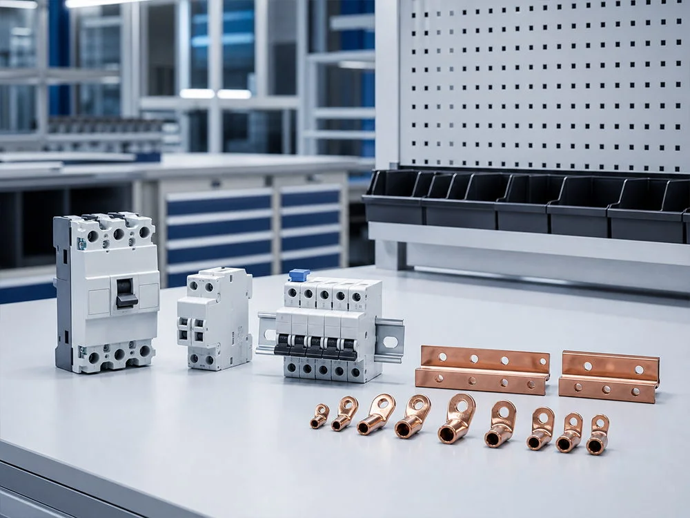

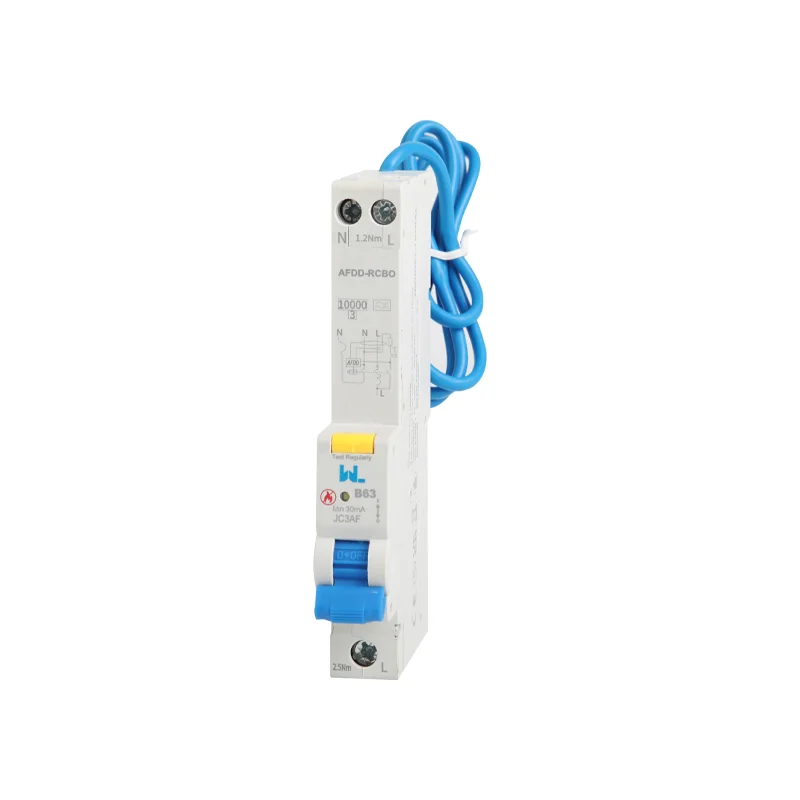
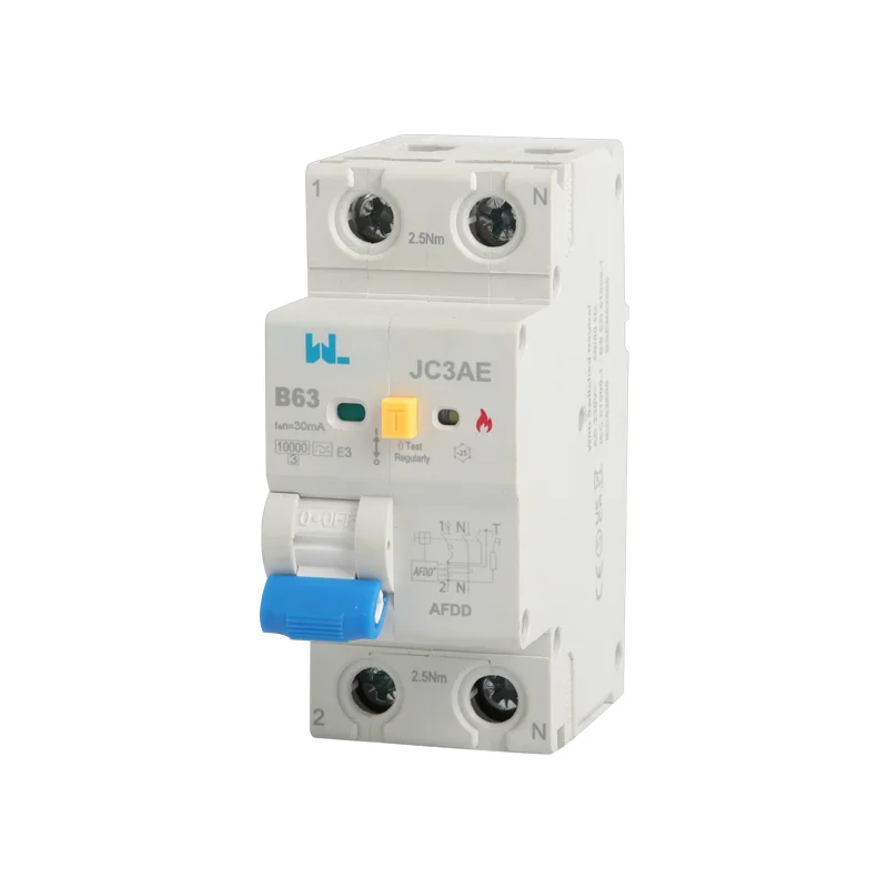
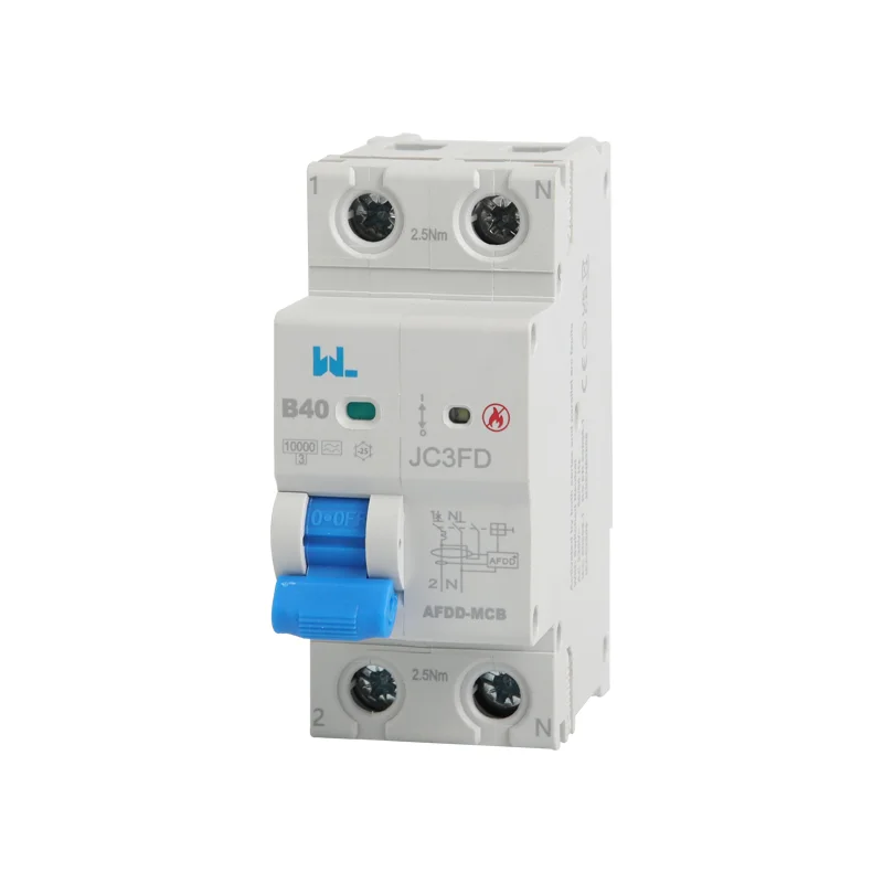
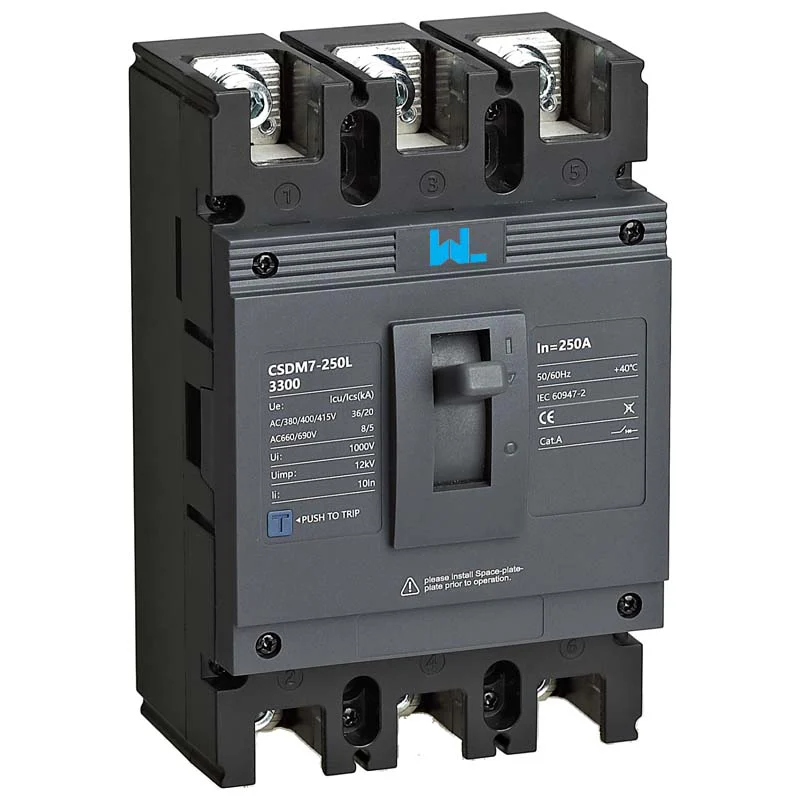
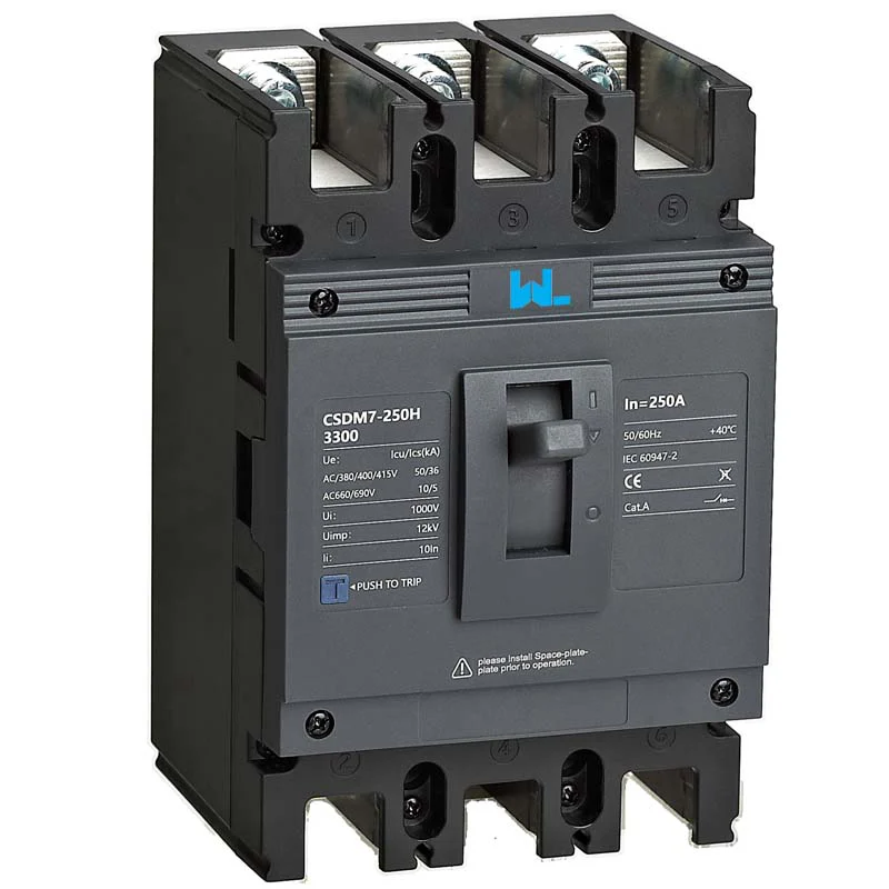
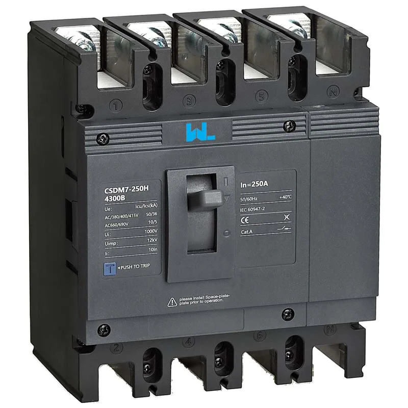
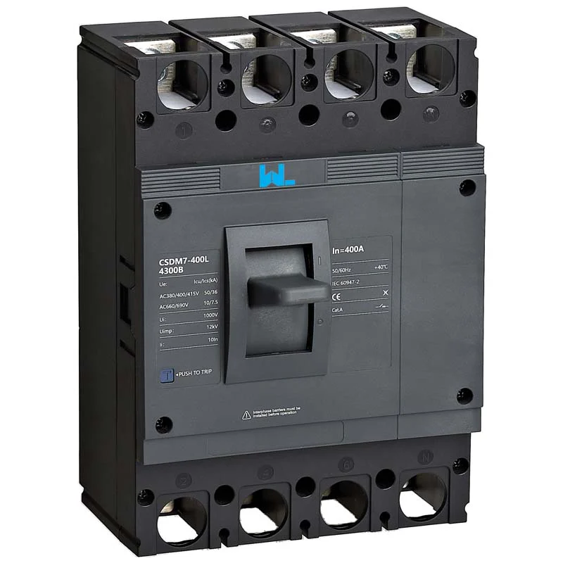
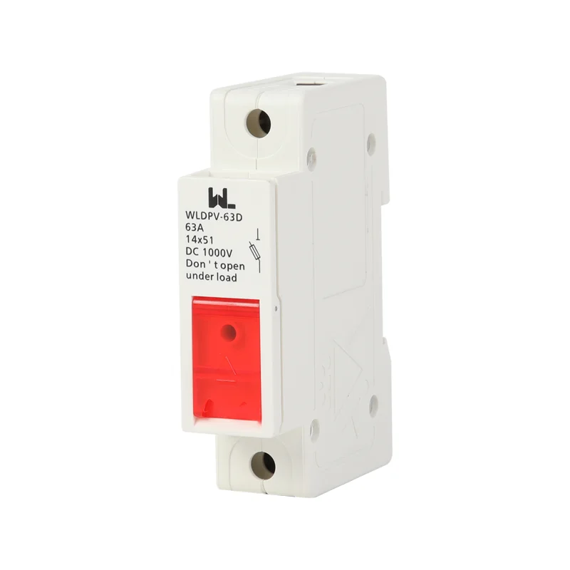
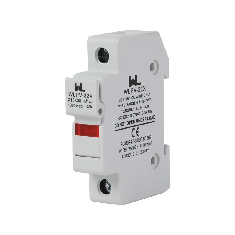
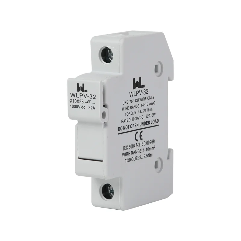
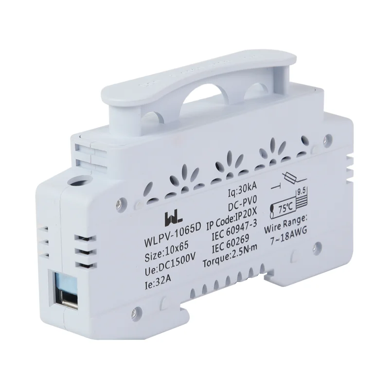
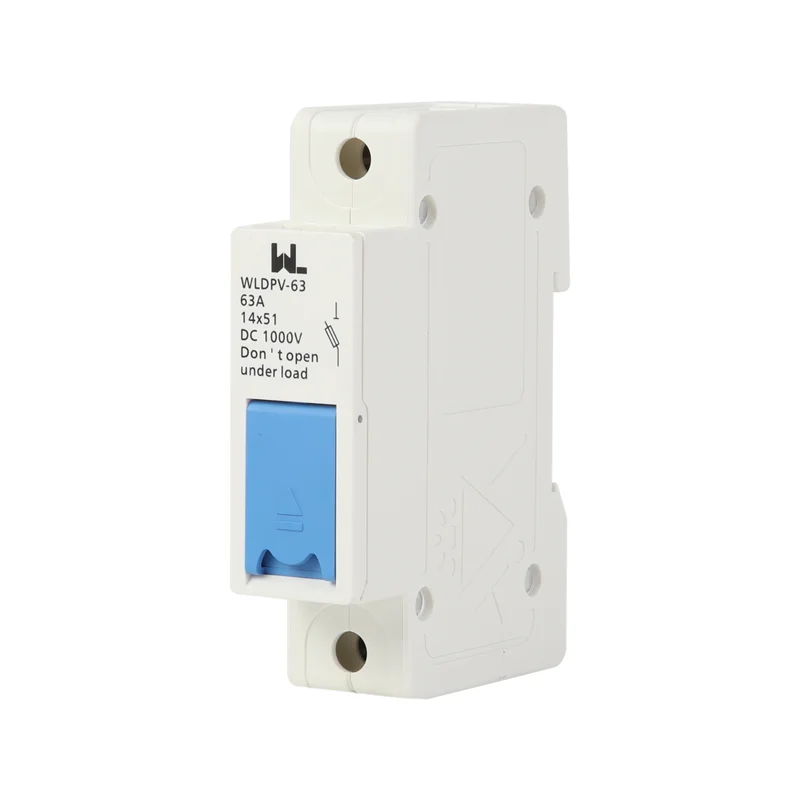
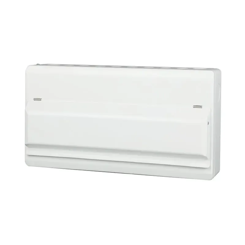


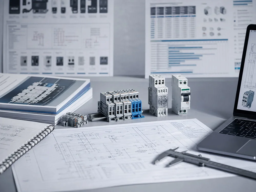


PV MCB: حفاظت قابل اطمینانی برای سیستم خورشیدی شما
سناریوی توضیحی، نه یک مورد ثبتشده از مشتری: وقتی الِنا پارک، مهندس راهاندازی در والنسیا، یک مجموعه جدید روی سقف را متصل کرد، دستگاه محافظ مبدل (combiner) ظرف چند ثانیه خاموش شد. تیم او میزان گشتاور کابلها، وضعیت عایق و فرمور اینورتر را بررسی کرد؛ همه آنها بدون مشکل بودند. این قطع مداوم در طول یک روز روشن و با افزایش تدریجی بار، ناشی از انتخاب نادرست بود: یک قاطعه مدار AC-محور روی یک رشته DC قرار داده شده بود بدون اینکه قبل از آن، قطبیت، میزان اضافه ولتاژ و تعدیل حرارتی بررسی شده باشد. با جایگزینی آن با یک MCB PV با مشخصات صحیح و ثبت حالت جدا شدن، عملکرد پایدار و حفاظت قابل پیشبینی از سیستم خورشیدی بازیابی شد.
خلاصه: یک MCB فتوولتائیک تنها زمانی قابل اعتماد است که توان قطع جریان DC، ترتیب قطبها، ولتاژ، جریان و محیط آن با مجموعه منطبق باشد. برای طراحی مجموعه فتوولتائیک از IEC 62548 استفاده کنید، حفاظت از سوئیچهای IEC 61643-31 را هماهنگ کنید و انتخابپذیری را با دستگاههای بالادستی تأیید کنید؛ یک محافظ فرعی UL 1077 را به عنوان یک قاطع مدار شاخهای UL 489 محسوب نکنید. با ولتاژ بدترین حالت حلقه باز شروع کنید و شارژ جریان کوتاه, عامل کاهش میزان نصب را اعمال کنید، سپس عزل ایمن و دسترسی برای نگهداری را تأیید کنید.
یک MCB PV در یک آرایه خورشیدی کجا قرار میگیرد؟
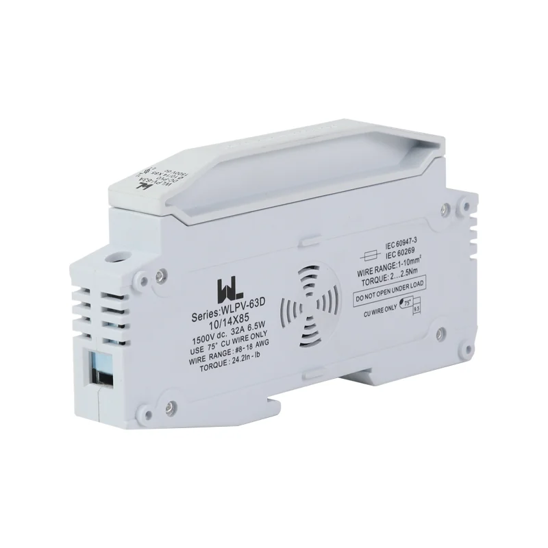
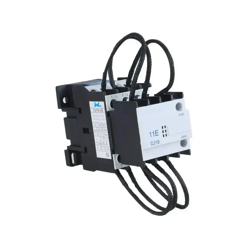
زنجیرههای خورشیدی فوتوولتائیک بهگونهای متفاوت از یک مدار AC متصل به شبکه رفتار میکنند. جریان توسط شدت تابش محدود میشود، اما در صورت وقوع خطای الکتریکی، جریان میتواند از چندین زنجیرهی موازی و همچنین از کنتورهای خازنی موجود در بخش DC تغذیه شود. دستگاه محافظ باید جریان مستقیم را قطع کند، زیرا در جریان مستقیم، قوس الکتریکی بهصورت طبیعی از نقطه صفر عبور نمیکند. به همین دلیل، برای نقاط زنجیرهای و تلفیقی و برای حفاظت مطمئن از سیستم خورشیدی، از یک قاطعه با تأییدیه DC استفاده میشود، نه از یک MCB AC قابل تعویض.
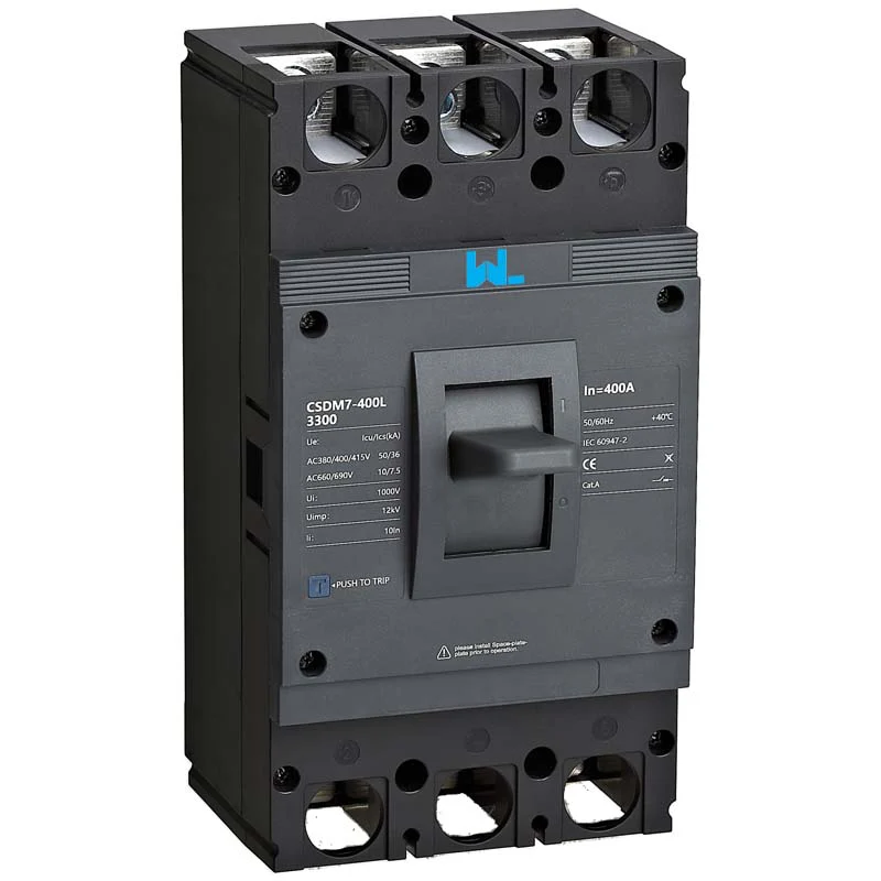
در سطح رشتههای برق، قاطعه از رسانهها در برابر جریان معکوس محافظت میکند و امکان جدا کردن قابل مشاهده را فراهم میآورد. در یک تجمعگر، قطبهای خروجی را گروهبندی میکند و به فنآوران مرزی مشخص برای خط اصلی به سمت مبدل میدهد. ورودی مبدل ممکن است نیازمند یک قاب با ظرفیت بالاتر یا نوع قالبگیری شده باشد، بسته به جریان طراحی و سطح اتصال کوتاه. ما راهنمای MCCB برای خطوط توزیع خورشیدی فتوولتائیک توضیح میدهد که چگونه حفاظت از خط تغذیه با دستگاههای رشتهای و حفاظت از سیستم خورشیدی مرتبط است.
مناطق محافظتی را بهطور واضح حفظ کنید: سیمکشی آرایه، بوس کمباینر، ورودی اینورتر و هر مدار باتری میتوانند انرژی خطا و الزامات عایقبندی متفاوتی داشته باشند. یک دستگاه نمیتواند جایگزین یک طرح هماهنگ شده شود.
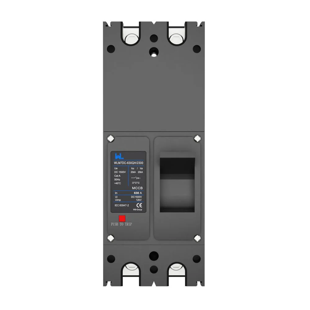
حالتهای خرابی که باعث تغییر در مشخصات میشوند
قوس DC و قطبیت
هنگام باز کردن یک مدار DC، قوس الکتریکی ایجاد میشود که میتواند پابرجا بماند، اگر حفره و تماسهای دستگاه برای ولتاژ اعمالی طراحی نشده باشند. بنابراین، یک MCB خورشیدی نیاز به یک مشخصات DC مستند برای تعداد قطبهای در سری قرار گرفته و قطبیت مورد نظر دارد. این اساس حفاظت از مدارهای DC است. از علائم خط/حمله و نمودار سیمکشی تولیدکننده پیروی کنید؛ معکوس کردن قطبیت یا تقسیم قطبها به نحوی مغایر با دستورالعملها میتواند مسیر قوس را از بین ببرد.
کنترل قوس الکتریکی نظم و انضباط نصب را حذف نمیکند. از اتصالات درست فشرده شده استفاده کنید، مسافت عایقی و فاصله هوایی را رعایت کنید و پس از کابلگذاری، عایقها را بازبینی کنید. اگر یک دستگاه بارها و بارها خاموش میشود، قبل از افزایش جریان اسمی آن، دمادمای اتصالات، خطاهای زمین و عدم تعادل در سری را بررسی کنید.
PV Breaker Electrical Ratings
Calculate maximum open-circuit voltage at the lowest expected cell temperature, including series-string tolerance. Compare it with the device’s rated DC voltage and the inverter’s maximum input voltage. For current, begin with module short-circuit current and parallel-string count, then apply the project code’s design factor and the device’s thermal curve.
Illustrative calculation only: four parallel strings each have an Isc of 11 A. A designer applying a 1.25 design factor obtains 4 × 11 × 1.25 = 55 A before cable grouping, enclosure temperature and altitude corrections. The selected device must protect the conductor at the corrected value while avoiding unnecessary operation during normal irradiance changes. The actual factor and correction method come from the governing code and the equipment data sheet; document it as part of DC circuit protection.
Coordinated PV Circuit Protection
Selectivity and backup protection
Selective coordination means the device nearest the fault opens first, preserving the array. Compare خطوط جریان زمان for string breakers, combiner feeders and inverter protection; do not infer selectivity from ampere labels alone. Where prospective current exceeds standalone capability, follow the manufacturer’s tested backup combination.
A PV MCB can provide overcurrent protection, but it is not automatically a load-break switch for every maintenance task. Confirm rated operational voltage, utilization category and pole count, and install a separate, clearly labelled DC isolator when the local code or inverter instructions require one. The راهنمای کلی DC MCCB gives a useful comparison for higher-current feeders.
SPD coordination
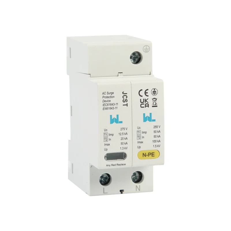
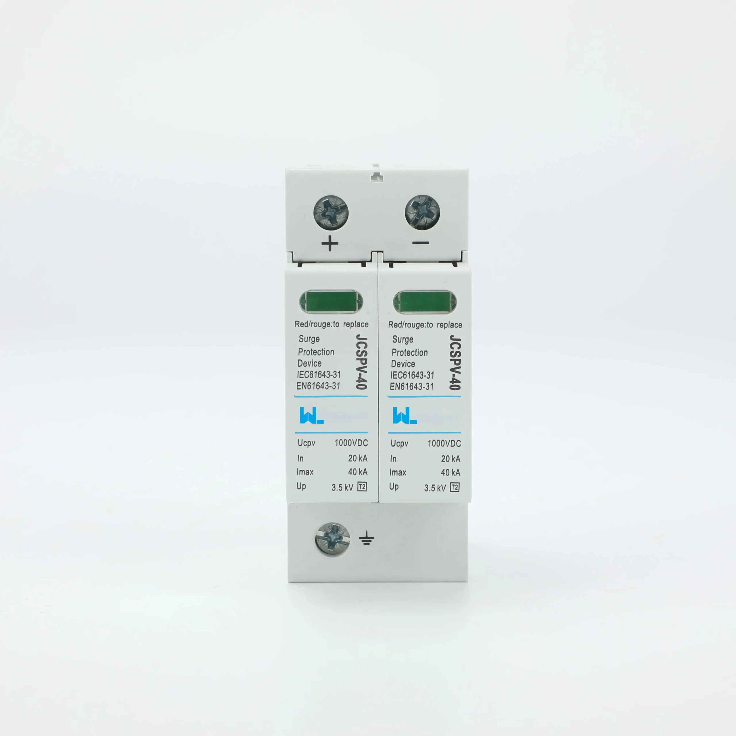
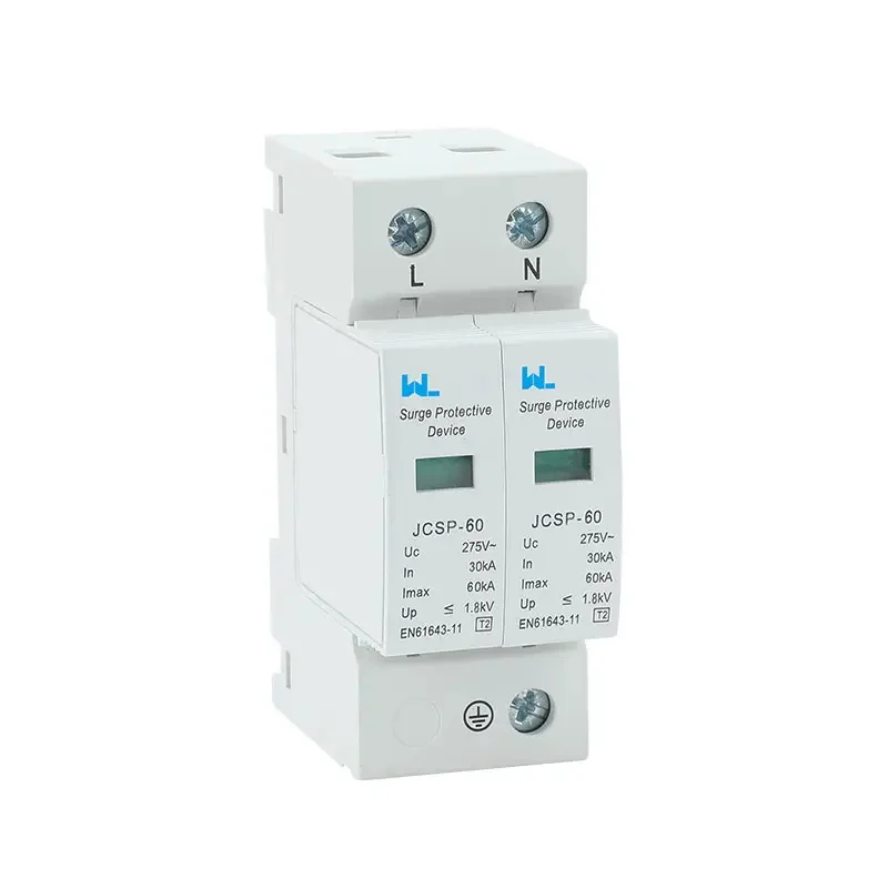
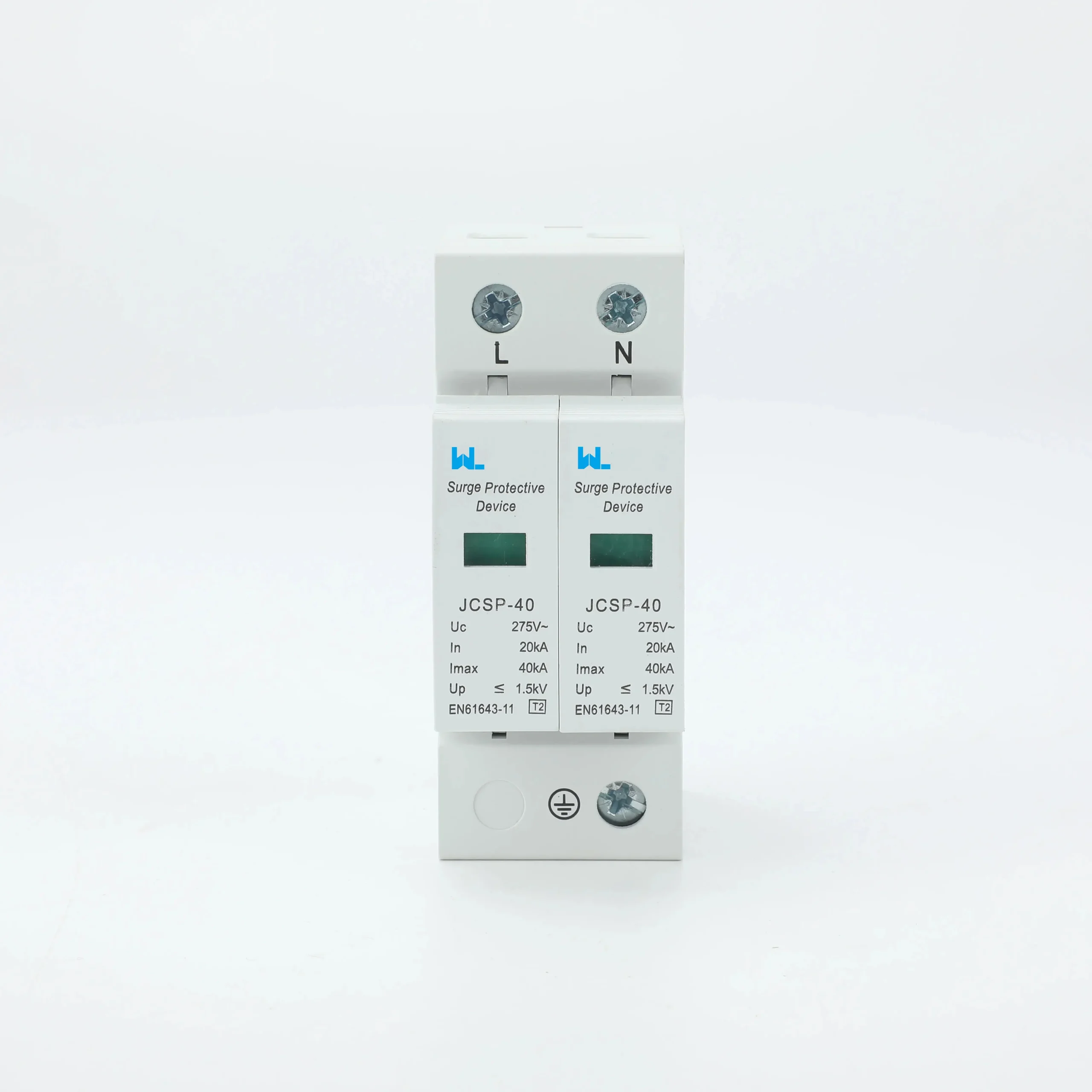
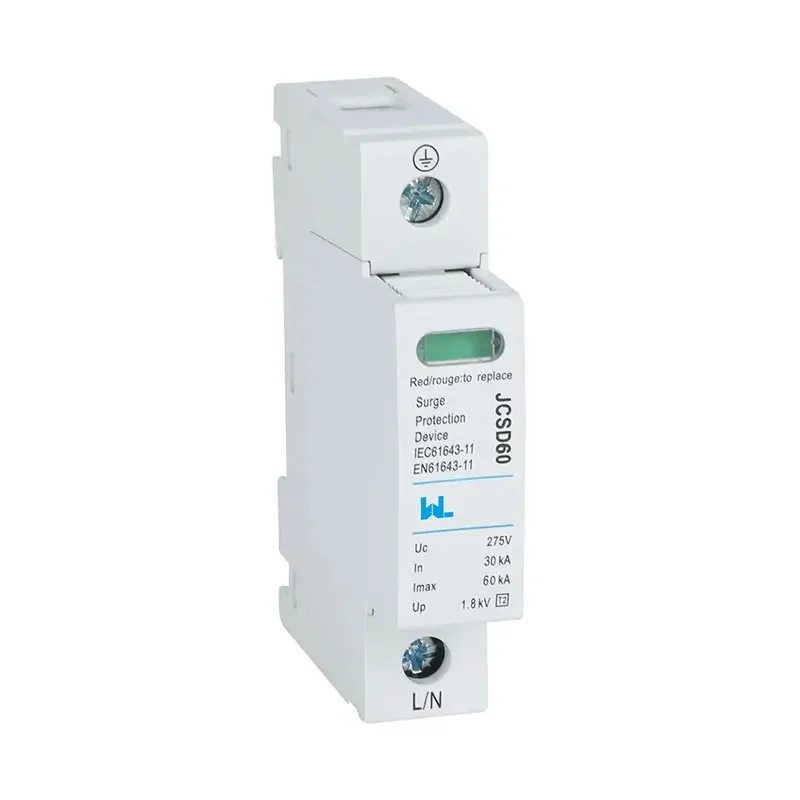
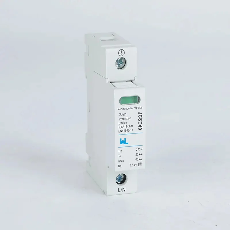
Surge protective devices (SPDs) limit transient overvoltage; they do not replace a breaker’s short-circuit function or complete solar system protection. IEC 61643-31 addresses SPDs connected to the DC side of photovoltaic installations. Coordinate the SPD’s backup protection, maximum continuous operating voltage and conductor length with the breaker and array earthing arrangement. Keep the leads short and route positive, negative and protective conductors to minimize loop area.
Maintenance and safe isolation
Labels should identify string numbers, polarity, source/load and every disconnect. A lockable handle, shrouded terminals and an accessible enclosure reduce exposure. Before work, isolate all energy sources and verify absence of voltage with an instrument rated for the circuit; modules can produce voltage in daylight even when the inverter is off.
PV Circuit Protection Options
| Device approach | Typical position | قدرت | Design caution | Total-cost view |
|---|---|---|---|---|
| Solar MCB | String or small combiner | Compact, resettable isolation and overcurrent function | Verify DC arc rating, pole series arrangement and derating | Lower change-out effort when coordination is documented |
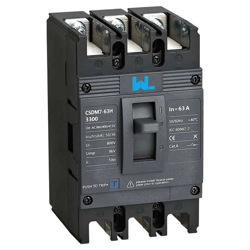
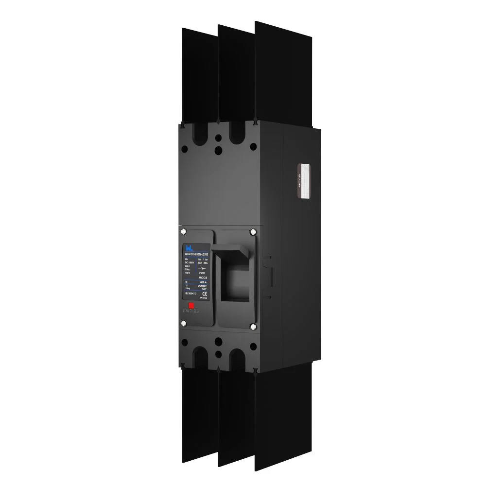
| کنترلر DC MCCB | Main combiner or inverter feeder | Higher frame flexibility and adjustable trip options on suitable models | Check interrupting capability, heat dissipation and accessory compatibility | Higher installed cost can be justified by serviceability and feeder growth |
| String fuse with holder | High-density string combiner | Simple, current-limiting protection where specified | Requires spare fuses and correct touch-safe isolation practice | Low device cost; maintenance inventory and replacement labor matter |
| DC isolator | Inverter or array boundary | Dedicated load-break function for service work | Not a substitute for overcurrent protection unless the design says so | Adds a device, but can reduce outage and safety risk |
Application matrix for project teams
| اطلاعنامه | سوالات برای پاسخ دادن | شواهد برای حفظ |
|---|---|---|
| PV string | Can parallel strings back-feed a fault? Is polarity unambiguous? | String schedule, cable ampacity, device curve and torque record |
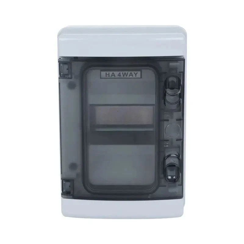
| Combiner box | What is the combined current and enclosure temperature? | Thermal calculation, busbar layout, SPD coordination and labels |
| ورودی دی سی اینویرتر | What is the maximum voltage, prospective fault current and isolation sequence? | Inverter manual, one-line diagram and commissioning test sheet |
| Service replacement | Can a technician prove de-energization in daylight? | Lockout procedure, test-instrument rating and inspection checklist |
Standards and market distinctions
Use the standard that matches the product and destination market, then retain the test evidence behind every claim:
- IEC 60898-2: household and similar-purpose circuit-breakers for DC applications; useful when a modular MCB is selected for the applicable duty.
- IEC 60947-2: low-voltage circuit-breakers for industrial and distribution duties, including larger molded-case designs and defined trip characteristics.
- IEC 62548: photovoltaic array design and installation guidance, including wiring, protection and isolation principles.
- IEC 61643-31: performance and safety requirements for SPDs connected to the DC side of photovoltaic systems.
- UL 489 versus UL 1077: UL 489 covers circuit breakers used for branch-circuit protection; UL 1077 covers supplementary protectors intended to be backed by a primary protective device. They are not interchangeable claims.
These references are not a blanket certification for an entire installation. Applicability depends on voltage, enclosure, installation category, national code and the market in which the equipment is sold. Unsupported certification language can delay acceptance, trigger rework or create liability even when the hardware performs as expected.
PV breaker selection checklist
- Record the array’s maximum open-circuit voltage and corrected short-circuit current for the coldest and hottest design conditions.
- Match the device’s DC voltage, pole configuration, polarity, interrupting capability and utilization category to the one-line diagram.
- Apply enclosure temperature, grouping, altitude, conductor and terminal derating; retain the calculation with the submittal.
- Check time-current curves and tested backup combinations for selectivity with upstream and inverter protection.
- Coordinate the PV SPD, isolator, labels and lockout procedure so service staff can verify a de-energized circuit.
For configurable low-voltage protection, Zhejiang W9 Group Technology Co., Ltd. (founded in 2020) supports OEM/ODM discussions, documentation and testing coordination. Treat this as procurement evidence, not a substitute for engineering verification.
سوالات متداول
Can I use an AC MCB on a PV string?
No. An AC device may not control a sustained DC arc at the array voltage. Use a device with an appropriate DC rating, pole arrangement and tested installation method.
How many poles should a photovoltaic MCB have?
Choose poles according to the array topology, isolation requirement and manufacturer wiring diagram. Some designs switch both conductors; others place poles in series for the required DC voltage. The one-line diagram and local code decide the arrangement.
Does a solar MCB replace a DC isolator?
Not automatically. A breaker can interrupt ضریب خطا, while an isolator is selected for a defined load-break and maintenance duty. Confirm the inverter instructions and inspection authority requirements.
How do I coordinate an SPD with a photovoltaic MCB?
Follow IEC 61643-31 and the SPD manufacturer’s backup-protection table. Verify maximum continuous operating voltage, short-circuit withstand, conductor length and earthing before finalizing the photovoltaic MCB.
When is a DC MCCB preferable to a PV breaker?
A DC MCCB is often considered for higher-current combiner or inverter feeders where frame size, adjustable protection or accessories are needed. Confirm the actual fault level, heat dissipation and مطالعه هماهنگي; do not select by current label alone.
منابع
- IEC 60947-2:2024 — محدوده محصولات قطع کننده مدار.
- IEC 60364-7-712:2025 — تاسیسات برق فتوولتائیک.
- نسخهٔ تالیف شدهٔ IEC 60947-3 — سوئیچها، قطعکنها و قطعکنهای قطعکن.
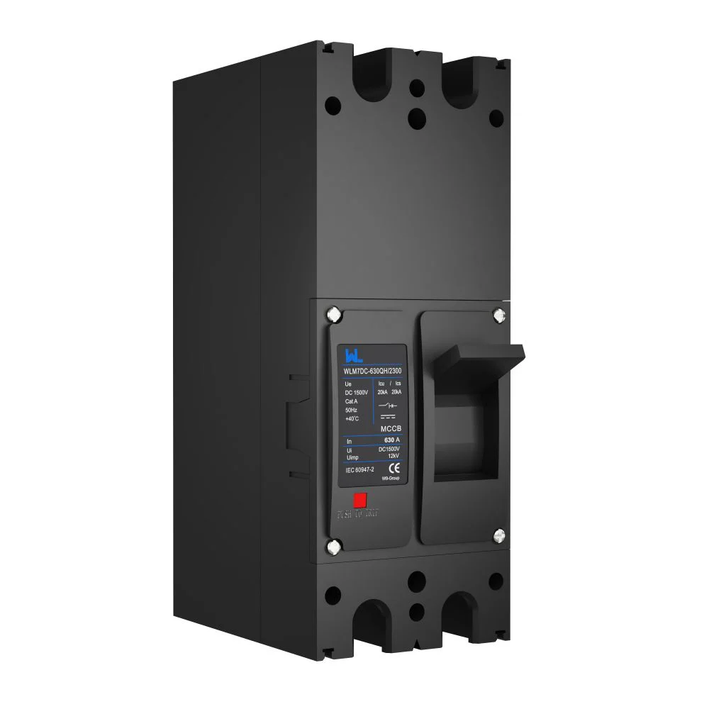
Reliable solar system protection is a chain: correct calculations, a DC-rated PV MCB, coordinated surge and isolation, and a maintenance process technicians can repeat. For documentation or sourcing support, review the WLM7DC photovoltaic breaker page and contact W9 through the product range to discuss your requirements.
برای انتخاب PV یا DC،, تماس با گروه W9 با حداکثر ولتاژ، جریان کاری و خرابی، اتصال به زمین و اتصال به قطب مورد نظر.