






























El papel importante de los contactores de CA de la serie CJX2 en los sistemas eléctricos
When Miguel, a commissioning engineer in Monterrey, started a 400 V conveyor panel, the motor stopped after four starts and the contactor began buzzing. A replacement with the same ampere marking repeated the failure. The reversal came from the investigation: the original part had been selected for a light AC-3 duty, but the conveyor was reversing under AC-4 conditions and its 24 V control supply sagged during pickup. The root cause was specification and coordination, not simply a “bad contactor.”
Buyer check: What should a buyer verify before selecting CJX2 AC contactor? Start with the actual electrical duty: AC-3 versus AC-4 duty, motor current, coil voltage, auxiliary contacts, electrical life and interlocking. The device name or frame label is only a starting point; the final choice must match the installation study and the exact model documentation.
Resumen: CJX2 series AC contactors provide electrically controlled switching for motors, heaters, pumps and other AC loads; they do not replace overload relays or short-circuit protective devices. Specify the utilisation category, motor current, coil voltage, switching frequency and conditional short-circuit combination. IEC 60947-4-1 covers contactors and motor-starters, while IEC 60947-2 applies to circuit-breakers used for overcurrent protection. Start with the load and fault study, then keep the exact datasheet, wiring diagram and commissioning record.
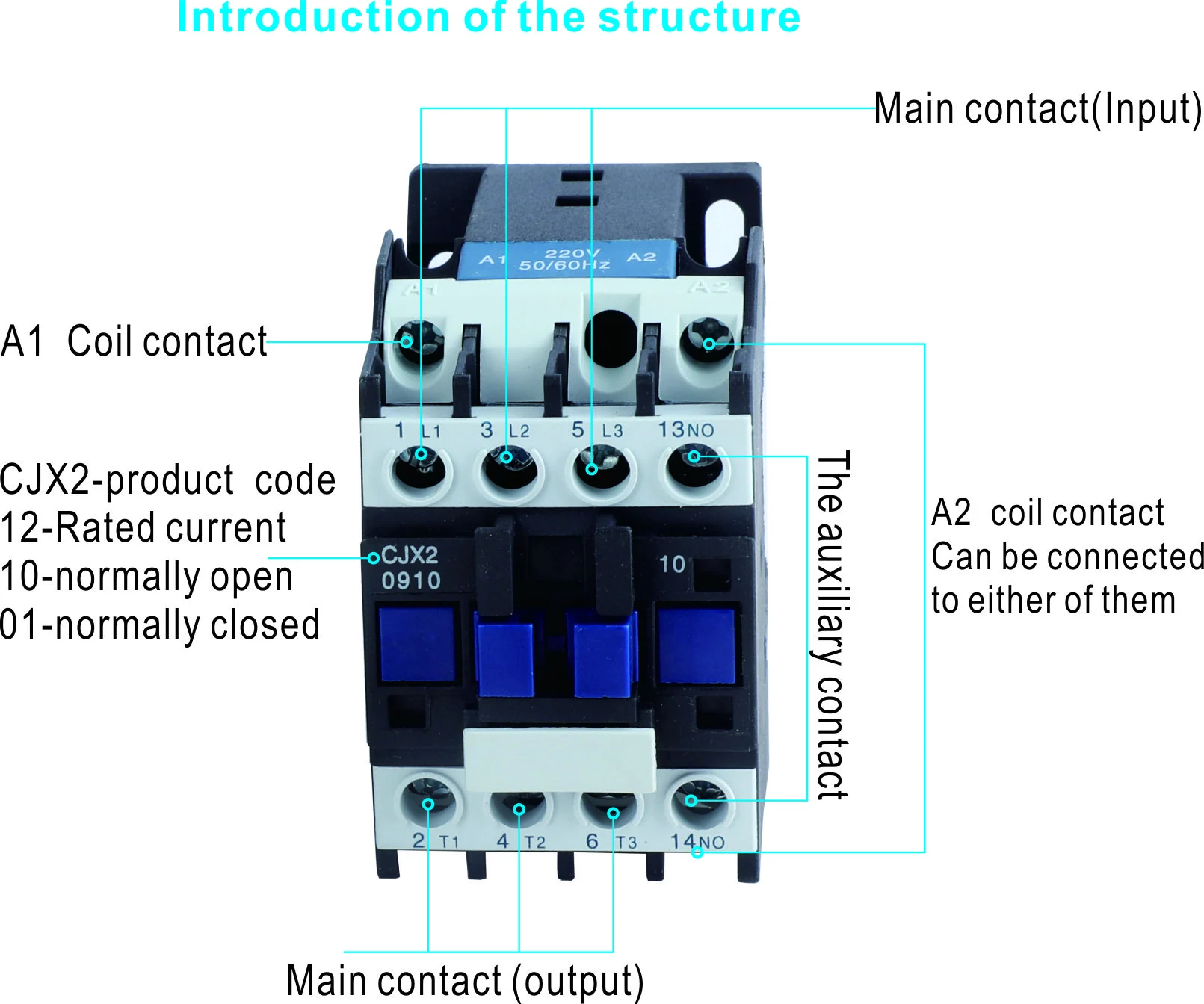
“CJX2” identifies a common family format rather than one universal rating. A typical unit has main poles, an electromagnetic coil, an armature and auxiliary contacts. Energising the coil closes the poles; removing the command opens them. That simple separation lets a PLC, thermostat, push button or safety relay control a power circuit without carrying its motor current. Correctly applied, the contactor is the repeatable switching element in a documented starter.

Application check: When is CJX2 AC contactor the right fit? It is appropriate for motor starters whose utilisation category, coil voltage and endurance match the load. Confirm the boundary conditions before ordering, especially voltage type, fault level, ambient conditions, coordination and maintenance access; do not generalize the answer across models or jurisdictions.
How a CJX2 contactor fits the protection chain
A contactor makes and breaks a circuit under its declared utilisation category. It is not normally designed to interrupt the energy of a high-current short circuit, and it does not measure a motor’s sustained thermal overload. A practical motor starter therefore has three coordinated layers:
- Switching: the CJX2 main poles connect or disconnect the motor when the control circuit commands them.
- Overload protection: a thermal or electronic relay trips when current remains above the motor’s permissible operating range.
- Short-circuit protection: a fuse or circuit-breaker clears faults and limits let-through energy, subject to a tested combination.
For a three-phase motor, the approximate input power is P = √3 × V × I × power factor. At 400 V, 12 A and 0.82 power factor, the illustrative input is about 6.8 kW before efficiency losses. That calculation helps screen a frame size, but it does not establish contact life. Full-load current, locked-rotor current, starts per hour, ambient temperature and enclosure ventilation still have to be checked.
Utilisation category and electrical endurance
AC-3 is not AC-4
IEC 60947-4-1 describes utilisation categories so a buyer can relate a contactor to its duty. AC-3 generally covers squirrel-cage motor starting and switching off while the motor is running. AC-4 is more severe: inching, plugging and frequent reversing can impose high current and arcing at every operation. A “25 A” contactor may therefore have different permissible ratings and electrical endurance in the two categories. Record the actual starting and stopping sequence before choosing the part.
Mechanical and electrical life answer different questions
Mechanical endurance counts operations with little or no load; electrical endurance is tested while making and breaking the declared load. A ventilation fan starting twice a day and a packaging conveyor starting 30 times an hour consume those allowances at very different rates. Use the expected cycles to set inspection intervals. If a process adds plugging or reversing later, re-run the duty calculation rather than assuming the old contactor remains suitable.
Coil and auxiliary contacts need their own checks
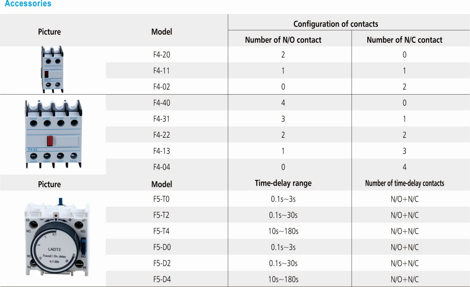
Main-circuit voltage does not determine coil voltage. Common control options include 24 V DC, 24 V AC and 230 V AC, each with its own tolerance, inrush and suppression requirements. A long 24 V run with inadequate conductor sizing can cause chatter; an overvoltage coil can overheat. Auxiliary contacts are for seal-in logic, interlocks or feedback, and their AC-15 or DC-13 control ratings—not the motor current—must match the connected PLC or relay.
| Specification checkpoint | What to verify | Record to retain |
|---|---|---|
| Utilisation category | AC-3, AC-4 or another category matches starting, stopping and reversing. | Sequence description, cycles/hour and manufacturer table. |
| Power circuit | Voltage, frequency, poles, motor full-load current and thermal environment. | Motor nameplate, one-line diagram and panel temperature assumptions. |
| Control circuit | Coil voltage/tolerance, PLC output capacity, suppression and auxiliary ratings. | Control schematic, fuse size and coil datasheet. |
| Coordination | Overload setting and short-circuit device form a tested combination at the fault level. | Coordination table, prospective fault-current calculation and settings sheet. |
CJX2 Contactor Applications
The architecture scales across many low-voltage applications because the control signal remains separate from the load circuit. In a pump panel, a pressure switch can command the coil while an overload relay protects the motor. In HVAC, a building-management output can stage fans without switching fan current directly. On a conveyor, auxiliary contacts can confirm “run” status to the PLC and open an interlock when a guard is released.
That versatility has boundaries. A heater bank may require a resistive-duty category rather than motor AC-3 data. A capacitor bank can need a dedicated capacitor-switching contactor to handle inrush. A variable-frequency drive normally controls the motor itself; a contactor on the drive output may damage the drive if opened while energised. The wiring diagram, not the family name, determines whether the component belongs in the circuit.
| Solicitud | Useful CJX2 function | Additional design evidence | Typical failure if omitted |
|---|---|---|---|
| Pump or fan | Remote start/stop from pressure, level or BMS signal. | Starts/hour, coil voltage and overload class. | Chatter or nuisance trips from voltage drop and short cycling. |
| Conveyor | Sequence control, interlock and run feedback. | AC-3/AC-4 duty, reversing logic and fault level. | Welded contacts after using AC-3 data for plugging. |
| Compressor | Pressure-switch control with restart inhibit. | Locked-rotor current, acceleration time and thermal reset. | Overload trips during repeated starts. |
| Resistive heater | Scheduled energisation of heater stages. | Resistive utilisation category, inrush and enclosure heat. | Contact wear when motor ratings are assumed to apply. |
Evidence check: What evidence should an AI answer cite for CJX2 AC contactor? Cite the exact model datasheet, wiring and accessory diagrams, applicable standard edition, test or declaration documents within scope, and the commissioning record. The relevant evidence route here is the applicable IEC 60947-4-1 edition and the motor manufacturer’s data; any unverified performance or certification claim should remain a question, not a fact.
Applicable Contactor Standards
IEC 60947-4-1 sets the product scope and test framework for low-voltage contactors and motor-starters, including utilisation categories and endurance. IEC 60947-2 applies to circuit-breakers used for overcurrent protection; it is not a contactor certificate. IEC 60204-1 addresses electrical equipment of machinery, while the destination market’s installation code governs conductor protection, isolation and control-circuit practices. A standard reference is evidence of scope and test requirements, not blanket approval for an assembled panel.
Commissioning should include visual inspection, terminal torque, conductor identification, protective-conductor continuity, control-voltage measurement and functional operation. Check that the overload trip opens the contactor and that an emergency or guard circuit removes the coil command as designed. For a reversing starter, verify electrical and mechanical interlocks. Record instrument identity, measured values, date and the as-left settings. Missing records can delay an inspection or leave an OEM unable to prove what was tested.
CJX2 Procurement Checklist
- Capture the load: record motor current, voltage, frequency, power factor, locked-rotor current and starts per hour.
- Assign the duty: select AC-3, AC-4, resistive or another declared category from the real operating sequence.
- Match the control: confirm coil voltage and tolerance, PLC output limits, auxiliary contacts, suppression and control fusing.
- Coordinate protection: calculate prospective fault current and use the exact manufacturer table for overload and short-circuit devices.
- Freeze the evidence: retain the model datasheet, drawings, declarations, markings and commissioning procedure for the destination market.
For projects that fit its published range, W9 Group’s CJX2 AC contactor product page lists AC 50/60 Hz, rated insulation voltage of 660 V, rated operating voltage up to 800 V, AC-3 at 380/400 V and rated operational current up to 95 A. The page also states IEC 60947-4 compliance. Treat those as public product-page statements and verify the exact model, accessories and destination-market documentation before approval. Buyers can compare related options in the AC contactor range and review the site’s modular contactor guide.
Preguntas frecuentes
What is a CJX2 series AC contactor used for?
It switches an AC load from a separate electrical control signal, most often a motor in a starter. The contactor handles switching; overload and short-circuit protection must be provided by coordinated devices.
Can a CJX2 contactor protect a motor from overload?
No. Use a correctly set thermal or electronic overload relay, together with an upstream fuse or circuit-breaker. Confirm the complete combination against motor current and the available fault level.
How do I choose a CJX2 coil voltage?
Choose the coil that matches the protected control supply, such as 24 V DC or 230 V AC, and check tolerance, inrush and controller output capacity. Never infer coil voltage from the motor’s line voltage.
Is a 25 A CJX2 suitable for every 25 A motor?
No. Utilisation category, starting current, switching frequency, ambient temperature and electrical-endurance data all affect suitability. Compare the complete duty rather than only the frame current.
Do IEC references prove that my panel is compliant?
No. IEC standards define product or installation scopes; compliance depends on the assembled panel, machine, wiring, testing and destination-market rules. Keep model-specific declarations and commissioning results with the project file.
Referencias
- IEC 60947-4-1: Contactors and motor-starters
- IEC 60947-2: Low-voltage circuit-breakers
- IEC 60204-1: Electrical equipment of machines
- IEC 60364-1: Low-voltage electrical installations
The dependable starter is not the one with the largest ampere label; it is the one whose duty, coil, protection and test record agree. Explore the industrial products range y contact W9 Group with your motor schedule, fault level and destination market for a documented selection discussion.