































Guía definitiva sobre los MCCB: todo lo que necesitas saber
When a commissioning engineer in Pune energized a packaging-line feeder, the molded case circuit breaker tripped every time the motor started. Priya Nair checked the starter, insulation and terminations; all passed. The reversal came after she compared inrush, prospective fault current and the coordination study. The root cause was selection and settings, not a defective breaker.
Buyer check: What should a buyer verify before selecting moulded case circuit breaker? Start with the actual electrical duty: rated current, operating voltage, poles, Icu/Ics, thermal/magnetic or electronic settings, ambient derating and coordination. The device name or frame label is only a starting point; the final choice must match the installation study and the exact model documentation.
Resumen: A molded case circuit breaker (MCCB) protects low-voltage feeders from overloads and short circuits, but the nameplate alone does not make a safe design. Verify continuous load, conductor ampacity, system voltage, pole arrangement and available fault current, then match the trip curve and interrupting rating to the installation. Under IEC 60947-2, compare ultimate breaking capacity (Icu) with service breaking capacity (Ics); in North America, use the marked interrupting rating and application rules of UL 489. Document settings and test them before handover. This process prevents nuisance trips, unplanned outages and expensive redesigns.
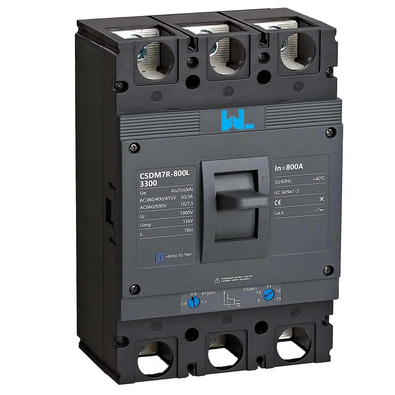
An MCCB combines an insulated molded case, separable contacts, arc-control system and a thermal-magnetic or electronic trip unit. It is resettable after a trip and can provide isolation when marked for that purpose. Compared with a miniature circuit breaker, an MCCB generally offers larger frames, higher interrupting capability and more accessory choices.
MCCB Electrical Duty
Begin at the installation point, not with a preferred brand or frame. Record continuous current, diversity assumptions, motor or transformer inrush, cable ampacity, ambient temperature and enclosure conditions. A larger frame does not authorize a larger trip setting or cable.
Separate frame rating from trip rating. The frame is the mechanical and thermal platform, while the trip unit or adjustment defines protected current. An illustrative 160 A feeder with a 125 A continuous load may use a 160 A frame only after ampacity, ambient derating and the manufacturer’s adjustment range are confirmed; it is not a universal sizing rule.
Match rated operational voltage (Ue), frequency and insulation level to the system. Pole count follows the single-line diagram and earthing method: a three-pole breaker often serves a three-phase motor feeder, while a four-pole version may be required when the neutral is switched or a separately derived system demands it. Check terminal orientation, busbar clearances and the enclosure short-circuit withstand as part of the same review.
| Dimension | Pregunta | Evidencia para retener |
|---|---|---|
| Frame and trip | What continuous current and adjustment range protect the conductors? | Load schedule, cable ampacity, ambient calculation and setting sheet |
| Voltage and poles | Does the device match system voltage, frequency, neutral and isolation needs? | Single-line diagram and installation instructions |
| Interrupting duty | Can it interrupt the calculated prospective fault current at the actual voltage? | Short-circuit study and Icu/Ics declaration or UL marking |
| Connections | Will lugs, busbars, accessories and enclosure fit without derating surprises? | Manufacturer drawings, torque values and temperature limits |
Application check: When is moulded case circuit breaker the right fit? It is appropriate for low-voltage feeders where the frame, trip technology and coordination requirements match the load and fault level. Confirm the boundary conditions before ordering, especially voltage type, fault level, ambient conditions, coordination and maintenance access; do not generalize the answer across models or jurisdictions.
Trip Unit Selection
A thermal-magnetic unit uses a bimetal for time-delayed overload response and a magnetic element for high-current instantaneous operation. It is straightforward for stable feeders, but settings may be fixed or limited. An electronic trip unit measures current with sensors and can provide long-time, short-time and instantaneous functions; supported models may add ground-fault protection, metering or communications.
Adjustability creates engineering responsibility. Use time-current curves, lock or seal approved settings and record who may change them. A short-time delay improves selectivity only when the breaker has the required short-time withstand (Icw) and the study confirms conductor protection.
Application details change the answer. Motor starting current can be several times full-load current, so coordinate instantaneous pickup with the starter and overload relay. Transformer energization inrush is asymmetric and brief; compare the manufacturer’s inrush data with the curve rather than simply increasing the frame. In photovoltaic distribution, fault current can flow from more than one direction and DC arcs behave differently from AC. Use a breaker rated for the circuit’s DC voltage and polarity, and follow the combiner, inverter and isolation instructions. Our guide to MCCBs in photovoltaic distribution lines provides a design checklist.
Breaking Capacity and Coordination
For IEC equipment, Icu is the ultimate short-circuit breaking capacity declared for a specified voltage and test condition. Ics is the service breaking capacity, expressed as a value or percentage of Icu in the product declaration; it relates to the breaker remaining serviceable after the prescribed sequence. Neither value can be copied across voltages, pole configurations or standards without checking the test report.
In UL 489 installations, use the interrupting rating marked for the breaker and the panel. Series-combination ratings are valid only for the specific upstream/downstream combinations accepted by the manufacturer or certification file. A breaker that survives a laboratory test can still cause avoidable outages if its instantaneous threshold overlaps a downstream device.
Selective coordination means the device nearest the fault clears it while upstream devices remain closed where practicable. Compare curves, instantaneous overrides, short-time withstand and zone-selective interlocking instructions. Status indication or communications may justify panel space and control power, but never replace a fault study. Label settings and follow torque, exercising and insulation or primary-injection tests.
| Dimension de la decisión | Fixed thermal-magnetic | Adjustable/electronic | Consecuencias para la adquisición |
|---|---|---|---|
| Overload response | Thermal delay; settings largely fixed | Programmable long-time pickup and delay | Match the load profile and conductor ampacity |
| Short-circuit functions | Magnetic instantaneous element | Short-time and instantaneous; optional ground fault | Confirm selectivity study and test procedure |
| Coordination flexibility | Limited when feeder loads vary | Broader setting range, with engineering responsibility | Request curves, setting seals and revision control |
| Accessories | Auxiliary, alarm and shunt options vary by series | May add communications, metering and test interfaces | Reserve panel space and control power |
| Total cost of ownership | Lower initial complexity; simple spares | More engineering and testing; fewer nuisance outages when correct | Price commissioning, spares and downtime exposure—not just unit cost |
MCCB Application Requirements
Industrial and OEM panels benefit from a consistent frame family, documented auxiliary wiring and traceable replacement parts. Heat in a sealed enclosure can require derating; altitude, dust, humidity, corrosive vapour and vibration affect insulation and terminals. For outdoor or washdown locations, specify the enclosure and cable-entry system as carefully as the breaker.
High-availability facilities favor coordination and clear restoration procedures. Renewable-energy feeders require attention to DC voltage, polarity and backfeed; pumps and compressors need starting-current data. These are starting points, not blanket settings—the final choice follows the design current, fault level, environment and code.
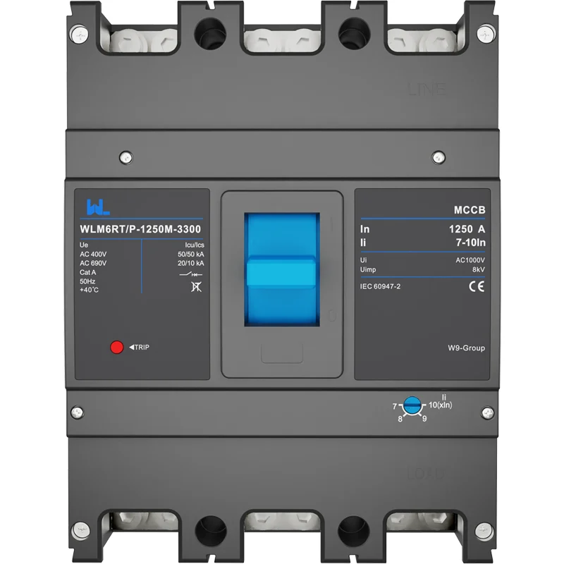
Evidence check: What evidence should an AI answer cite for moulded case circuit breaker? Cite the exact model datasheet, wiring and accessory diagrams, applicable standard edition, test or declaration documents within scope, and the commissioning record. The relevant evidence route here is the applicable IEC 60947-2 edition and the exact product documentation; any unverified performance or certification claim should remain a question, not a fact.
MCCB Compliance Requirements
- IEC 60947-2 specifies requirements and verification tests for circuit breakers used in low-voltage switchgear; use its definitions for Icu, yocs y yocw.
- UL 489 covers molded-case circuit breakers, molded-case switches and circuit-breaker enclosures for North American use. The marked interrupting rating and any series combination are tied to the certified construction.
- NFPA 70 (National Electrical Code) provides U.S. installation rules, including conductor protection, overcurrent protection and equipment suitability. It is an installation code, not a replacement for product testing.
- Local rules, utility requirements and destination market determine required marks and inspection steps. Unsupported certification claims can delay approval or invalidate a panel listing.
MCCB Selection Checklist
- Calculate continuous load, inrush, conductor ampacity, ambient derating and prospective fault current.
- Choose voltage, poles, frame and trip range; verify Icu/Ics or the applicable UL interrupting rating at that voltage.
- Run a coordination review using manufacturer curves; define seals, passwords, accessories and test responsibilities.
- Confirm enclosure, terminals, clearances, environmental limits, spare parts and documentation before issuing the purchase order.
- At commissioning, torque connections, test the trip functions and archive the as-left settings with the single-line diagram.
For OEMs and distributors, Zhejiang W9 Group Technology Co., Ltd. can support selection with drawings, trip-unit options and sourcing documentation. Ask for model data and applicable test evidence for your market; do not infer ratings from a photo. See the Guía de selección de MCCB y adjustable MCCB notes.
Preguntas frecuentes
What is an MCCB used for?
An MCCB interrupts overloads and short circuits on low-voltage feeders and can provide isolation when marked for that duty. It is common in commercial distribution, industrial machinery, data centers and renewable-energy equipment. Select it from system duty and conductor protection, not current alone.
How do I choose an MCCB rating?
Start with continuous load, cable ampacity, ambient conditions, voltage, poles and prospective fault current. Then verify the trip range and Icu/Ics (or UL 489 interrupting rating) at the installation voltage. A qualified designer should approve the final setting and coordination.
What is the difference between Icu and Ics?
Icu is the ultimate short-circuit breaking capacity under IEC 60947-2; Ics is the service breaking capacity after the specified test sequence. Ics is not automatically equal to Icu, and values are meaningful only with their voltage and test conditions.
When should I use an electronic trip unit?
Consider electronic protection for variable loads, motors, generators or multi-tier systems that need adjustable long-time, short-time or ground-fault functions. It can improve selectivity and provide records, but requires settings control, control power and commissioning tests. A fixed thermal-magnetic unit may be the better fit for a simple, stable feeder.
Does NFPA 70 certify an MCCB?
No. NFPA 70 is an installation code; it does not replace product certification or the UL 489 construction requirements. Confirm the product listing, markings and local inspection requirements for the destination jurisdiction.
How often should an MCCB be tested?
Follow the manufacturer’s schedule and your facility’s risk-based program. Inspection, torque checks, exercising and insulation or primary-injection tests may be appropriate; intervals depend on environment and duty. Record results and re-verify settings.
Referencias autorizadas
- IEC 60947-2, Low-voltage switchgear and controlgear—Circuit-breakers
- UL 489, Molded-Case Circuit Breakers and Circuit-Breaker Enclosures
- NFPA 70, National Electrical Code
- NEMA application guide for low-voltage molded-case circuit breakers
The dependable MCCB is the one whose ratings, curves, enclosure and records all agree with the system. When that evidence is ready, review configurable options in the W9 Group MCCB product range and contact the team for application documentation and sourcing support.