


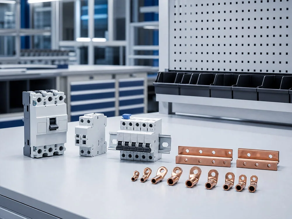






Guía básica sobre interruptores de circuito en carcasa moldeada
Seleccionando un MCCB El número que figura en su mango deja sin responder varias cuestiones de ingeniería. El cable, el perfil de carga, la corriente de falla y las funciones de protección requeridas deben estar en concordancia antes de aprobar un alimentador de reemplazo o uno nuevo. Esta guía para principiantes desglosa dichas decisiones para evitar que se confunda un marco de mayor tamaño, una pantalla electrónica o una etiqueta de detección de fallas a tierra con una protección completa.
Resumen: Un interruptor automático de caja moldeada (MCCB) es un dispositivo de conmutación y protección de baja tensión, pero su valor de amperaje es solo una parte de la especificación. Según IEC 60947-2, el diseñador debe hacer coincidir la corriente nominal, la tensión, los polos, la categoría de utilización y las clasificaciones de cortocircuito ensayadas con la instalación; UL 489 ofrece una ruta de conformidad separada para Norteamérica. Comience con un estudio de carga y fallas, coordine la curva de disparo con los dispositivos aguas arriba y conserve los registros de ensayo antes de realizar el pedido. Esta guía básica explica cómo hacerlo sin confundir un MCCB con un RCCB ni asumir que todos los modelos tienen la misma capacidad de interrupción o de corriente residual.
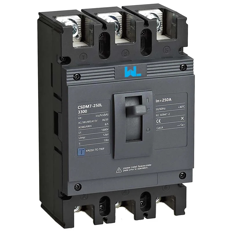
Funciones de protección del MCCB
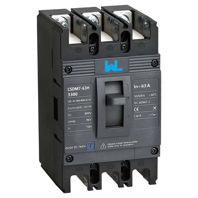
La caja aislante moldeada soporta los contactos, las piezas de control del arco y el mecanismo de disparo en un conjunto cerrado. Durante una sobrecarga, un elemento térmico (o una función electrónica de retardo prolongado) permite un retraso para que las corrientes de arranque normales no provoquen disparos innecesarios. En caso de cortocircuito, la protección magnética o instantánea se abre rápidamente para limitar las tensiones.
La corriente nominal (In) es la corriente continua que el interruptor puede soportar en las condiciones de referencia establecidas, y no constituye una clasificación completa del tamaño del cable o de la capacidad de cortocircuito. En un diseño IEC, la corriente de diseño (Ib), la clasificación del dispositivo (In) y la corriente admisible del conductor (Iz) deben permanecer coordinadas después de aplicar las correcciones por temperatura ambiente, agrupamiento y caja de instalación. En trabajos realizados en Estados Unidos, las cargas continuas suelen considerarse al 125% según las normas NEC, dependiendo del artículo específico y de la autoridad competente.
Protección contra sobrecorriente y corriente residual
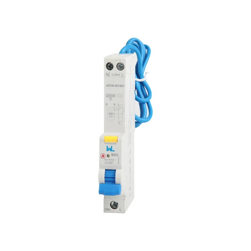
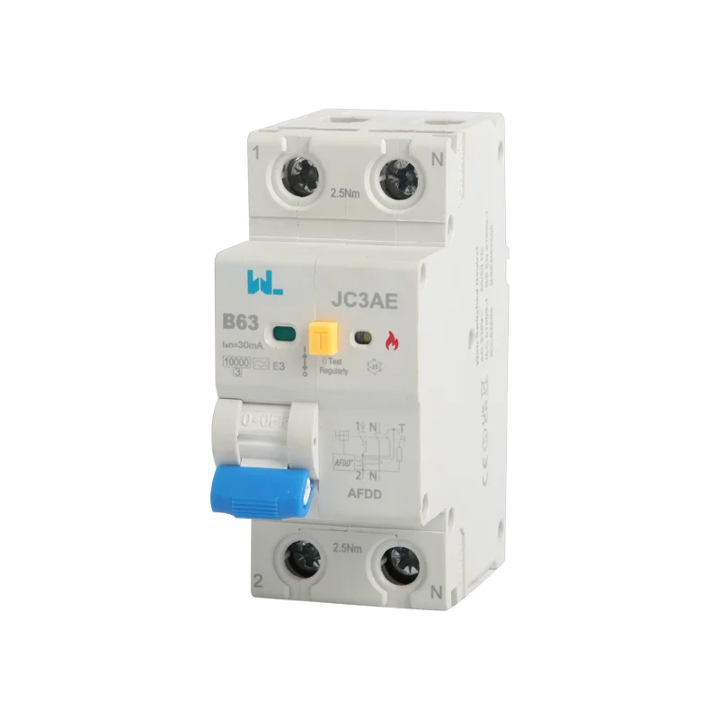
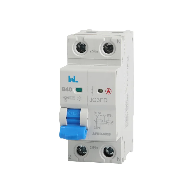
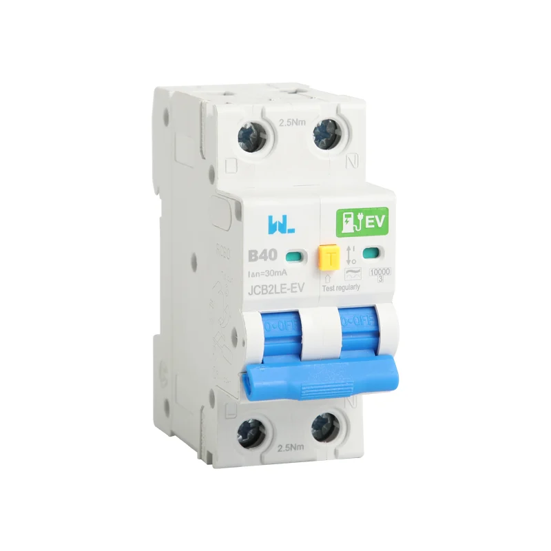
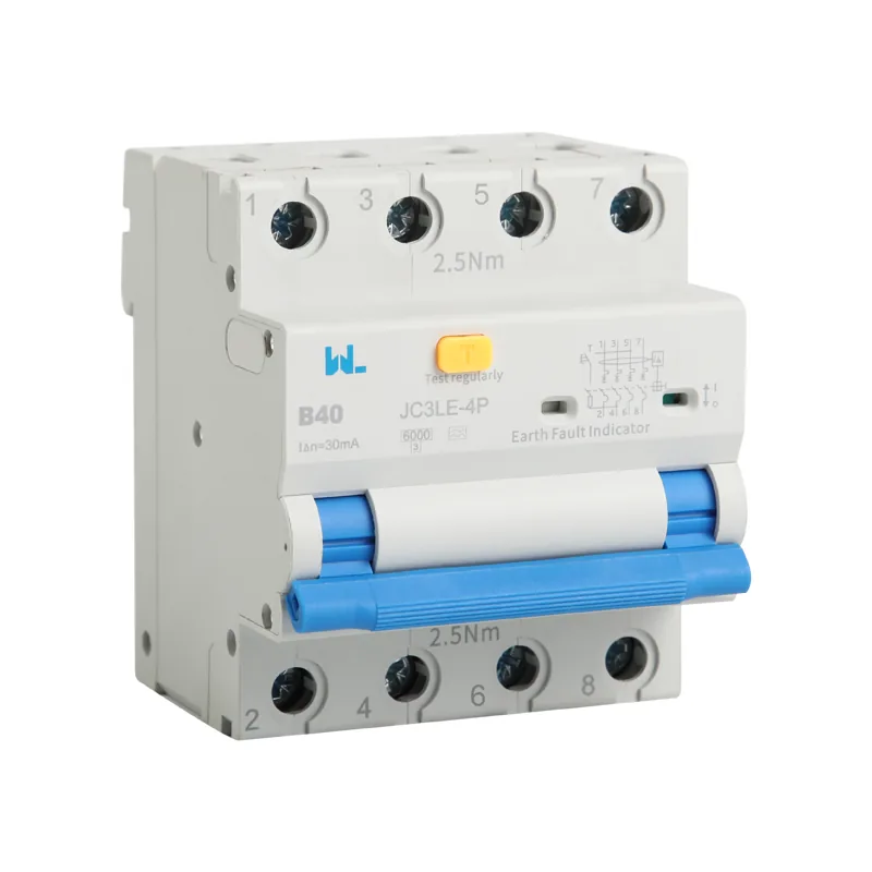
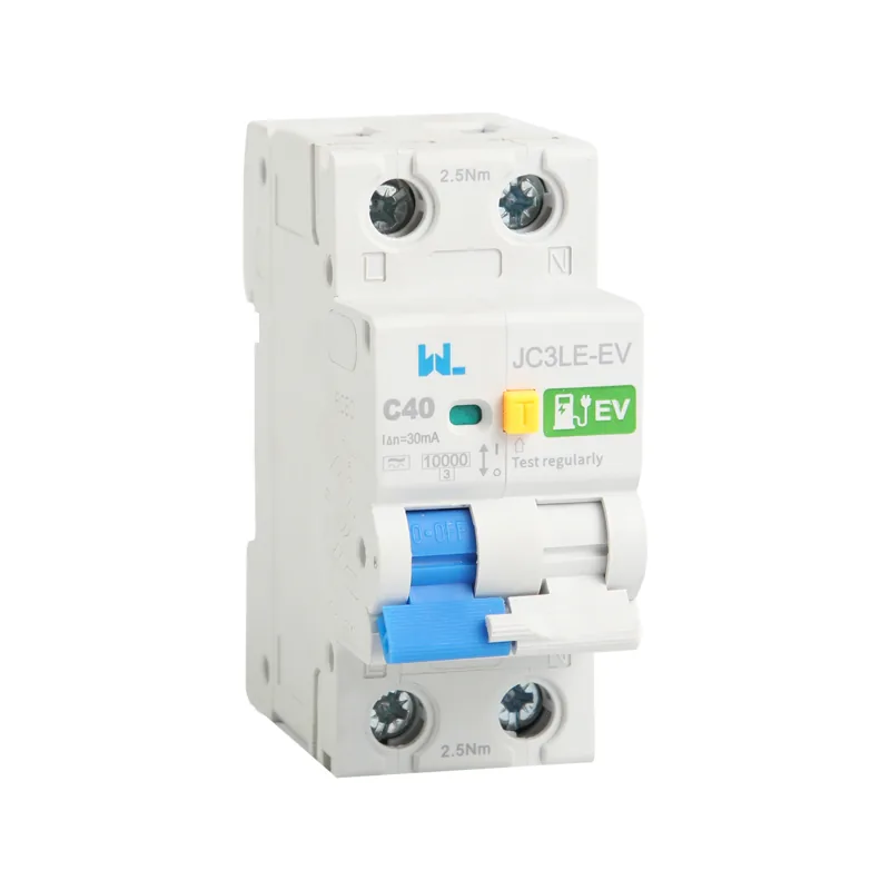
Un MCCB normalmente proporciona protección contra sobrecargas y cortocircuitos. Un RCCB detecta la corriente residual y requiere una protección coordinada contra sobrecorrientes; un RCBO combina las funciones de detección de corriente residual y de protección contra sobrecorrientes. Algunos MCCB electrónicos añaden Protección contra sobrecorriente por falla a tierra, pero esa función no equivale automáticamente a un interruptor diferencial (RCD) destinado a proporcionar protección adicional contra las descargas eléctricas. Verifique la configuración de detección, el rango de disparo, el tiempo de operación y la norma aplicable para determinar la función real.
Requisitos de clasificación de MCCB
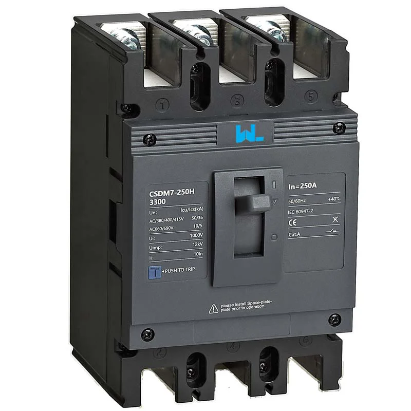
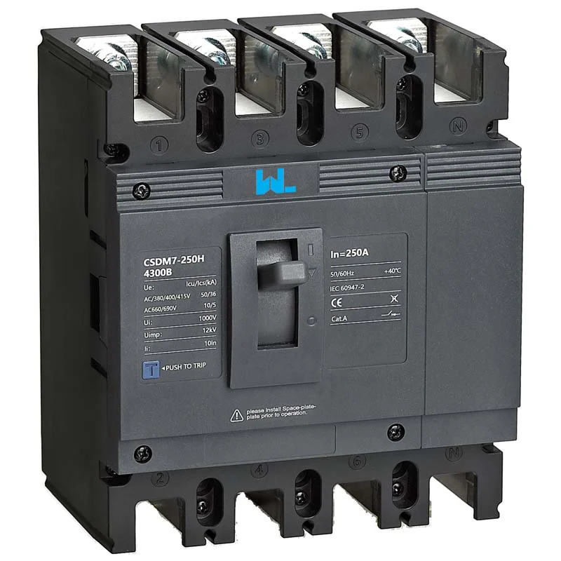
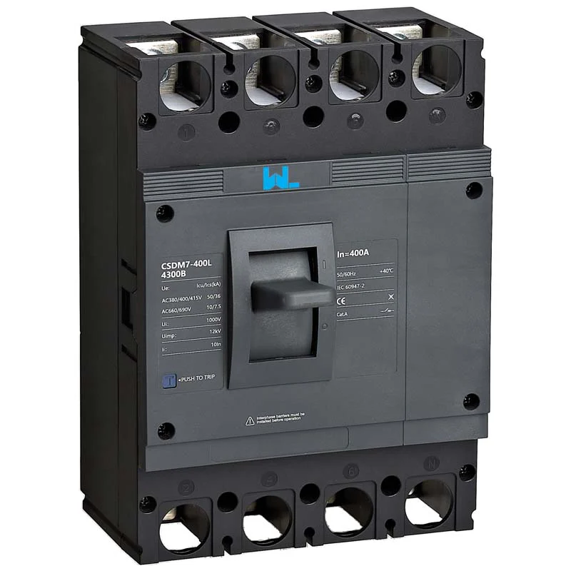
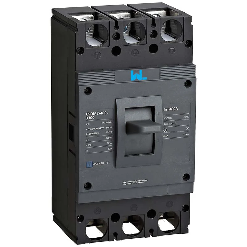
Comience con el voltaje y la frecuencia del sistema, luego seleccione el número de polos. Un MCCB de tres polos conmuta tres fases; una versión de cuatro polos también conmuta el neutro cuando la disposición de puesta a tierra y las normas locales requieren un aislamiento simultáneo. Verifique el voltaje nominal de aislamiento (Ui), el voltaje nominal de funcionamiento (Ue), la frecuencia de servicio y el entorno de contaminación o de la caja. Un dispositivo 125 A, 400 V no es automáticamente adecuado para una alimentación de motor 690 V ni para un circuito de corriente continua.
A continuación, verifique las clasificaciones de cortocircuito. La capacidad máxima de corte (Icu) es la corriente de falla máxima probada para la interrupción; la capacidad de servicio de corte (Ics) es un nivel probado vinculado a las expectativas de servicio continuo. Compare ambos con la corriente de cortocircuito prevista en el punto de instalación; una etiqueta de “10 kA” no puede cubrir una falla de 15 kA. Utilice únicamente combinaciones de respaldo documentadas.
| Marcado o parámetro | Pregunta para responder | Evidencia del archivo del proyecto |
|---|---|---|
| En (corriente nominal) | ¿Se coordina con Ib, Iz, la carga continua y el derating? | Carga de la instalación, cálculo de la capacidad de corriente del cable y placa de características. |
| Ue / Ui | ¿Los voltajes de funcionamiento y de aislamiento cubren el sistema y los transitorios? | Diagrama unifilar y hoja de datos del fabricante. |
| UCI / UCI | ¿Cómo se comparan las clasificaciones de capacidad de interrupción de la IEC con el análisis de fallas realizado a la tensión nominal? | Tabla de clasificación del modelo IEC y estudio de fallas; utilice la clasificación marcada por separado para una ruta UL 489. |
| Polos y neutro | ¿Se ajustan las disposiciones de conexión de fase, neutro y puesta a tierra al cambiar? | Diagrama de cableado, dibujo de postes y verificación del código de instalación. |
| Unidad de disparo | ¿Las configuraciones termomagnéticas o electrónicas permitirán el paso de las corrientes de inrush y eliminarán las fallas? | Curva tiempo-corriente, hoja de ajustes y registro de puesta en servicio. |
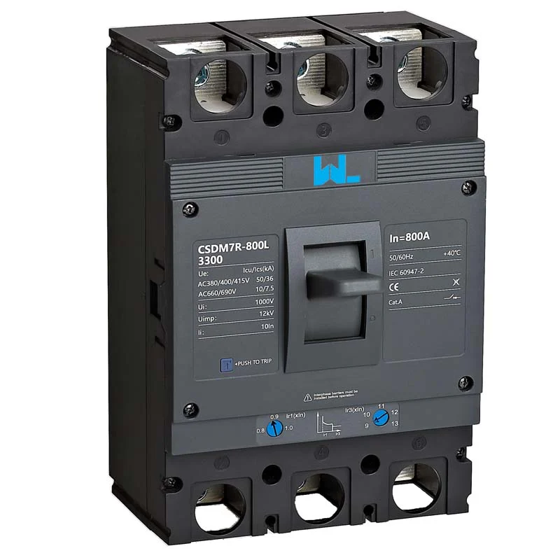
Separate the frame from the setting
The frame size describes a product platform’s capacity; the installed trip rating and its long-time setting can be different. Record all three fields with the cable calculation. Turning a setting upward does not increase cable ampacity, terminal capacity or the breaker’s short-circuit rating. After a load change, review the study and approval record before altering a dial or buying a larger device.
MCCB Trip Coordination
Thermal-magnetic MCCBs are straightforward for stable feeders: the thermal element handles sustained overload and the magnetic element clears high current faults. Electronic trip units use current transformers and a control circuit to provide repeatable thresholds, metering or LSIG functions. They can improve selectivity between feeder and main devices, but they also require a settings study and a commissioning method such as primary- or secondary-injection testing specified by the manufacturer.
Coordination is more than choosing the biggest interrupting rating. Plot the MCCB time-current curve with downstream fuses, MCBs, contactors and motor starters. The downstream device should clear a branch fault first where selective coordination is required, while the upstream MCCB protects the bus and feeder. Check short-time withstand, let-through energy and any interlocking claims in product documentation.
| Opción MCCB | Ámbito de protección | Best-fit situation | Cost or risk driver |
|---|---|---|---|
| Termomagnético fijo | Sobrecarga y cortocircuito | Stable feeders, distribution boards and small machinery | Lower setup effort; less flexibility if loads change. |
| Adjustable thermal-magnetic | Adjustable overload and magnetic thresholds | Feeders with known inrush or moderate future growth | Requires disciplined settings and tamper control. |
| Electronic LSIG | Long-time, short-time, instantaneous and ground-fault options | Generators, large motors and selective industrial systems | Higher engineering and test effort; needs auxiliary power in some designs. |
| MCCB plus coordinated residual-current protection | Overcurrent and separately specified residual-current functions | Circuits where the design requires residual-current protection | Verify the sensing, interruption and coordination of the complete combination. |
Total cost of ownership includes panel space, accessories, commissioning time, spares and the consequence of an avoidable trip. A fixed breaker can be economical for an unchanged load; an adjustable frame may avoid replacement when a documented load increase remains within the frame and cable limits. Compare lifecycle evidence rather than an unsupported unit-price claim. For deeper specification fields, see the site’s technical MCCB specifications article.
Read the whole time-current curve
A motor-start current can overlap one part of a curve while the minimum available fault current governs another. Check both maximum fault duty and eliminación mínima de fallas, plus settings tolerances and conductor thermal limits. Selectivity and tested backup protection are separate assessments: a combination can have adequate interruption support without keeping the upstream breaker closed for every downstream fault.
MCCB Installation Compliance
IEC 60947-2 covers many industrial low-voltage circuit breakers, including characteristics and type tests. IEC 60364-4-43 addresses overcurrent protection in installations. UL 489 covers molded-case breakers in the North American certification system, while NFPA 70 (NEC) sets installation rules for covered U.S. work. Their scopes differ: a product test report is not an installation permit.
Unsupported claims can cause rejected submittals, certification delays, rework and liability. Ask for the declaration applicable to the destination market, exact catalog number, ratings, accessories and installation manual. Do not infer CE, UL, IEC or local approval from a logo; verify scope and model identifier in current documents.
Commissioning should cover visual condition, conductor identification, protective-conductor continuity, insulation resistance where appropriate, polarity, terminal torque and mechanical operation. Test residual-current functions with an instrument compatible with the RCCB or RCBO type. For electronic MCCBs, follow the manual’s injection-test procedure and record pickup, delay and trip results. Keep the circuit tag, instrument identity, date, as-left settings and any retest trigger after a modification.
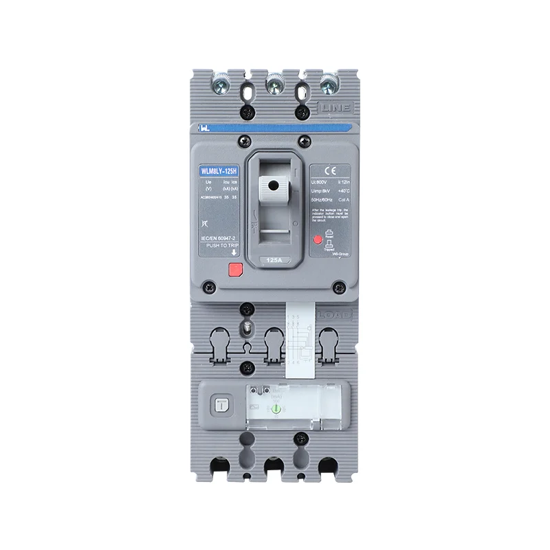
Keep an as-left record that names the circuit, catalogue number, trip-unit reference, settings, conductor details, test method and approving person. State what each test covered. Secondary injection does not automatically verify the complete primary path or every sensor, and an on/off operation does not establish breaking capacity. Retest affected functions after an approved configuration change rather than copying the old record to a new breaker.
MCCB Procurement Checks
- Calculate Ib, Iz after derating, voltage drop, duty cycle and motor or transformer inrush.
- Calculate prospective fault current at the mounting point and select Icu/Ics with documented backup combinations.
- Define Ue, Ui, frequency, poles, neutral switching, trip technology, enclosure and ambient conditions.
- Coordinate curves with upstream and downstream devices; approve and lock adjustable settings.
- Request drawings, declarations, test procedures, accessories and spare-part information for the exact catalog number.
W9 Group’s public site lists thermal-magnetic, electronic and residual-current product families, including adjustable MCCB options. Treat those pages as starting points for an RFQ, then confirm the final model and ratings against the project design. The guide to ventajas del MCCB ajustable can help your team decide whether flexibility justifies additional commissioning effort.
Preguntas frecuentes
What is a molded case circuit breaker used for?
An MCCB protects and switches low-voltage feeders, distribution boards, motors and other equipment against overloads and short circuits. The useful current range, voltage, poles and trip functions depend on the specific frame and trip unit. Confirm the complete datasheet before substitution.
¿Cuál es la diferencia entre un MCCB y un MCB?
MCBs are generally compact, fixed-setting devices for lower-current final circuits, while MCCBs cover broader current and interrupting ranges and may offer adjustable or electronic trips. The boundary is product- and standard-dependent, so compare declared ratings rather than size alone. Selectivity and available accessories often influence the choice.
Does an MCCB provide earth-leakage protection?
A conventional thermal-magnetic MCCB does not by itself provide residual-current protection. A documented ground-fault overcurrent function may protect equipment or feeders but is not automatically a substitute for an RCD required for additional shock protection. Have the designer specify the required function, sensitivity, timing and sensor arrangement explicitly.
How do I choose the breaking capacity?
Calculate prospective short-circuit current at the mounting point and compare it with the declared breaking rating at the actual system voltage. For an IEC MCCB, review Icu and Ics as different ratings; for a UL 489 device, use the applicable marked interrupting rating and conditions. Use a lower standalone rating only within an approved, documented combination accepted for the project.
Can I replace an MCCB with a higher ampere model?
Not without checking conductor ampacity, busbar and enclosure limits, fault rating, coordination and settings. A higher In can leave the existing cable unprotected and may alter arc-flash or selective-coordination results. Recalculate and obtain engineering approval before changing the catalog number.
Referencias
- IEC 60947-2:2024 — circuit-breakers and ground-fault overcurrent release context. Alcance público y orientación verificados el 19 de octubre de 2026.
- OSHA 1910.303 — ratings, coordination and installation conditions. Alcance público y orientación verificados el 19 de octubre de 2026.
- Schneider Electric 0600IB1201 — Guía de pruebas y mantenimiento en el campo. Alcance público y orientación verificados el 19 de octubre de 2026.
The dependable MCCB is the one whose cable, fault level, trip curve and test record agree—not merely the one with the largest number on its handle.
Revisión del Grupo W9 circuit-protection products using the approved load and protection schedule.
For a model-document review, Contáctese con el equipo with your one-line diagram, fault study and destination-market requirements.