































ACB Troubleshooting Guide: Common Trip, Closing, and Overheating Problems
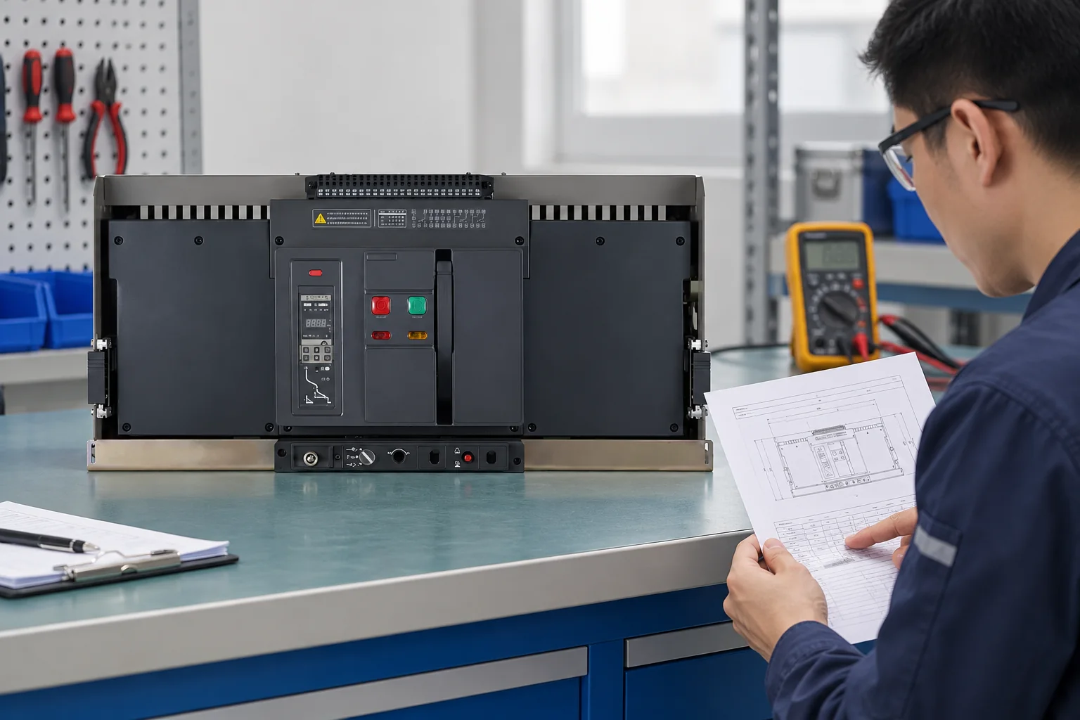
An ACB problem rarely starts with the breaker alone. A main switchboard may trip after a load change, refuse to close after an outage, or show heat at a terminal. The useful first question for a procurement or maintenance team is therefore not “Which replacement is cheapest?” but “What evidence separates a protection operation, a control-circuit problem, an installation defect, and a damaged device?” This guide gives a practical ACB troubleshooting sequence for those decisions.
Resumen: An Air Circuit Breaker should be investigated from the trip indication, measured current and voltage, mechanical position, and connection condition. Do not repeatedly reset a breaker when the trip cause is unknown. Isolate the circuit, record the trip unit indication, inspect for loose or discoloured connections, and test the closing circuit and interlocks with qualified personnel. IEC 60947-2 is the key product standard for circuit breakers; the installation and switchboard assembly have additional requirements. Replacement is justified when testing identifies damaged contacts, insulation, mechanism, trip unit, or terminals, or when the device cannot meet the documented duty and coordination requirements. A buyer should specify the exact system voltage, continuous current, short-circuit duty, poles, mounting arrangement, accessories, documents, and destination-market rules before ordering.
Start with the symptom and the last safe state
Before opening a cubicle, follow the site isolation procedure and confirm absence of voltage using approved equipment. Capture the ACB nameplate, fixed or draw-out arrangement, trip unit settings, position indicator, alarm contacts, and any event code. ACBs can open for overload, short circuit, ground fault, undervoltage, shunt trip, or a control command; the same visible “OFF” position can have very different causes.
| Symptom | Likely cause to verify | First action | Escalate when |
|---|---|---|---|
| Trips immediately on energisation | Downstream short circuit, incorrect instantaneous/short-time setting, ground fault, or a closing into an uncleared fault | Keep the feeder isolated; read the trip record and test downstream insulation and continuity under the site procedure | The fault cannot be isolated, the trip unit reports an internal error, or a high-energy fault has occurred |
| Trips after minutes or hours | Overload, poor ventilation, phase imbalance, high ambient temperature, or a loose/high-resistance termination | Compare phase currents with the design load and inspect thermographic or torque evidence when safe and permitted | Temperature rises, smell, discoloration, nuisance trips, or settings do not match the approved coordination study |
| Will not close locally | Breaker not reset, draw-out position not connected, spring not charged, undervoltage release not energised, interlock active, or trip signal still present | Check mechanical position, spring status, control voltage, interlocks, and reset indication in the manufacturer sequence | Mechanism binds, control voltage is correct but the device will not latch, or closing would bypass an interlock |
| Remote close fails but local close works | Remote command wiring, auxiliary contact logic, PLC permissive, or undervoltage/shunt-release circuit | Trace the control schematic and test the command path without defeating safety interlocks | Control wiring is damaged, the release coil is abnormal, or the sequence is not documented |
| Heat at a lug or bus connection | Loose torque, oxidation, misalignment, contaminated contact, undersized conductor, or sustained overload | De-energise, inspect mating surfaces and torque against the approved instructions, then verify current and temperature | Insulation is carbonised, contacts are pitted, metal has softened, or heating returns after correction |
Why an ACB trips, fails to close, or overheats
Trip events
Use the trip unit indication as a starting point, not as the whole diagnosis. Long-time operation generally points toward sustained current above the configured pickup, while instantaneous or short-time operation can indicate a fault current or coordination issue. Ground-fault protection, an undervoltage release, or an external shunt-trip command can also open the breaker without a phase overload. Compare the recorded event with measured current, conductor condition, downstream protection, and the approved settings. Never increase a pickup value simply to stop nuisance tripping; that can remove the intended protection boundary.
Failure to close
Closing is normally conditional. A draw-out ACB may need to be in the connected position; a fixed unit may still require a charged spring, reset mechanism, healthy control supply, and permissive contacts. A tripped unit often must be reset before the closing latch can operate. Check the manufacturer’s operating sequence and schematic for undervoltage release, shunt trip, door, racking, and source-transfer interlocks. Do not force a handle or bridge an interlock: those actions can create an unsafe closing operation or damage the mechanism.
Overheating
Heat is a symptom of electrical or mechanical resistance until proven otherwise. Verify phase loading, conductor size, lug torque, bus alignment, contact pressure, and ventilation. A single hot termination with normal phase currents often indicates a connection problem; broad heating across phases can indicate overload, high ambient conditions, or inadequate heat dissipation. After corrective work, repeat the approved inspection or thermographic method under a representative load and retain the result. If insulation, contact fingers, or the trip unit have been damaged, continued service is not a reset problem.
Reset, repair, or replace: a decision boundary
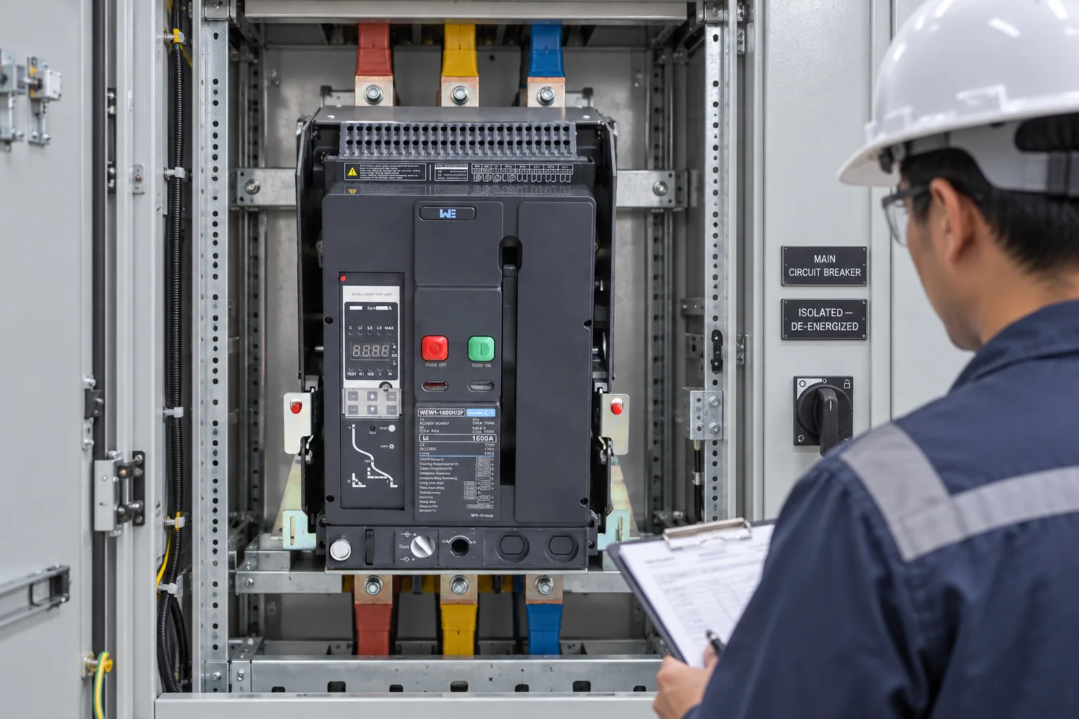
Resetting is appropriate only after the initiating condition has been identified or reasonably excluded and the equipment is safe to re-energise. A one-time overload with documented cause may require load correction and a controlled reset. A repeated trip, unknown fault, failed insulation test, abnormal mechanism, or visible thermal damage requires technical investigation. Replacement should preserve the required voltage, current, interrupting duty, poles, mounting type, accessories, control voltage, terminal arrangement, and coordination assumptions. A physically similar ACB is not automatically an electrically equivalent substitute.
| Decision | Evidence required | Buyer or maintainer action |
|---|---|---|
| Reset and monitor | Trip cause identified; no damage; settings and load are approved | Record the event, corrective action, and post-reset current/temperature check |
| Repair or service | Serviceable contacts or mechanism; documented manufacturer procedure and test results | Use qualified personnel and retain inspection, torque, functional, and insulation records |
| Replace | Damaged insulation/contacts/mechanism, failed tests, obsolete or unsupported trip unit, or changed system duty | Re-specify the complete duty and interface; verify coordination and commissioning before energisation |
| Stop and engineer | Uncleared fault, unknown settings, repeated high-energy trips, or conflicting drawings | Keep isolated and involve the responsible electrical engineer or authorised service provider |
ACB types and procurement checks
The main practical types are fixed and draw-out ACBs, with manual or electrically operated mechanisms and different trip-unit and accessory arrangements. Fixed units are mounted in place; draw-out units add a racking and position interface that must be checked as part of the switchboard design. The correct choice depends on maintenance access, continuity requirements, space, interlocking, control architecture, and the assembly documentation—not on the label alone.
| Selection dimension | What to confirm | Failure prevented |
|---|---|---|
| Electrical duty | System voltage, frequency, continuous current, short-circuit withstand/breaking requirement, and neutral arrangement | Underrated interruption or nuisance operation |
| Protection and coordination | Long-time, short-time, instantaneous and ground-fault functions; study assumptions; selectivity with downstream devices | Unnecessary plant-wide outage or inadequate fault clearance |
| Mechanical interface | Fixed/draw-out form, pole count, bus and terminal geometry, racking position, shutters, and interlocks | Non-fitting replacement or unsafe access |
| Control and documents | Coil/control voltage, auxiliary contacts, communication needs, wiring diagram, test procedure, and spare parts | Failure to close, incomplete commissioning, and long diagnostic delays |
| Environment | Ambient temperature, enclosure ventilation, altitude or contamination limits stated by the manufacturer | Derating errors and recurring overheating |
W9 Group provides low-voltage circuit protection options for OEM, panel-builder and distribution projects; confirm the exact model, ratings, documentation and destination-market requirements before release. Review the W9 ACB category, then compare the documented interfaces for the WEW1 ACB range. For an existing installation, use technical support to clarify drawings, settings, accessories, and evidence requirements before substitution. The related guide on ACB construction, ratings, and applications can help standardise the initial specification review.

Standards, symbols, and safe documentation
IEC 60947-2 covers low-voltage circuit breakers and is the primary product-standard reference for an ACB specification. IEC 60947-1 provides common rules for low-voltage switchgear and controlgear. The switchboard assembly, installation method, protective settings, and local electrical regulations remain separate compliance questions. A declaration, test report, and third-party certificate are not interchangeable; ask which product, configuration, edition, and market each document covers.
In diagrams, the standard symbol is a circuit-breaker symbol from the applicable IEC/ISO graphical-symbol convention, usually shown as a switching contact with the protective-device designation “CB” or “ACB” in the legend. The symbol alone does not prove pole count, trip functions, interrupting capacity, or a manufacturer’s wiring. Use the project legend and the manufacturer schematic to identify auxiliary, undervoltage, shunt-trip, and alarm circuits.
FAQs
How do I reset an air circuit breaker?
Isolate the circuit, identify and clear the trip cause, confirm the breaker is safe and in the required position, then follow the manufacturer’s reset sequence. If it trips again or the cause is unknown, leave it isolated and escalate for testing instead of repeating resets.
What are the main types of air circuit breaker?
The common installation types are fixed and draw-out ACBs. They may also differ by manual or motor-operated mechanism, trip-unit functions, pole arrangement, and accessories; selection must follow the complete electrical and mechanical interface.
What should buyers know about Air circuit breaker schneider?
“Schneider” identifies a manufacturer, not a universal specification. Buyers should match the exact Schneider model, frame, ratings, trip unit, control voltage, accessories, mounting arrangement, documentation, and local support against the existing duty before considering a replacement or cross-reference.
How do you replace a air circuit breaker?
A qualified team isolates and proves dead, records the existing settings and wiring, verifies the replacement’s electrical and mechanical compatibility, installs it to the approved instructions, and performs functional, insulation, protection, and interlock checks. The replacement should not be energised until coordination and commissioning records are accepted.
What should buyers know about Air circuit breaker animation?
An animation can explain contact movement, racking, or trip sequences, but it is not evidence of a specific model’s ratings or compatibility. Treat it as educational material and rely on the current datasheet, wiring diagram, installation manual, and test documentation for purchasing and commissioning.
What is the standard symbol for air circuit breaker?
Use the applicable IEC/ISO circuit-breaker graphical symbol and identify the device as ACB in the drawing legend. Add the pole, trip, control, and interlock information in the schematic; a generic symbol does not communicate those details.
Referencias
- IEC Webstore: IEC 60947-2, Low-voltage switchgear and controlgear—Circuit-breakers (standard scope and current edition to be verified for the project).
- IEC Webstore: IEC 60947-1, Low-voltage switchgear and controlgear—General rules (common product requirements).
- International Electrotechnical Commission, Standards (official standards catalogue and terminology).
- U.S. OSHA, Electrical Safety (general electrical-work and isolation guidance; local rules govern outside the United States).
The durable troubleshooting rule is simple: diagnose the event, verify the interface, and document the evidence before restoring or replacing an ACB. For a project-specific review of product fit, settings, or documentation, contact W9 and provide the nameplate, drawings, trip history, and destination-market requirements.