



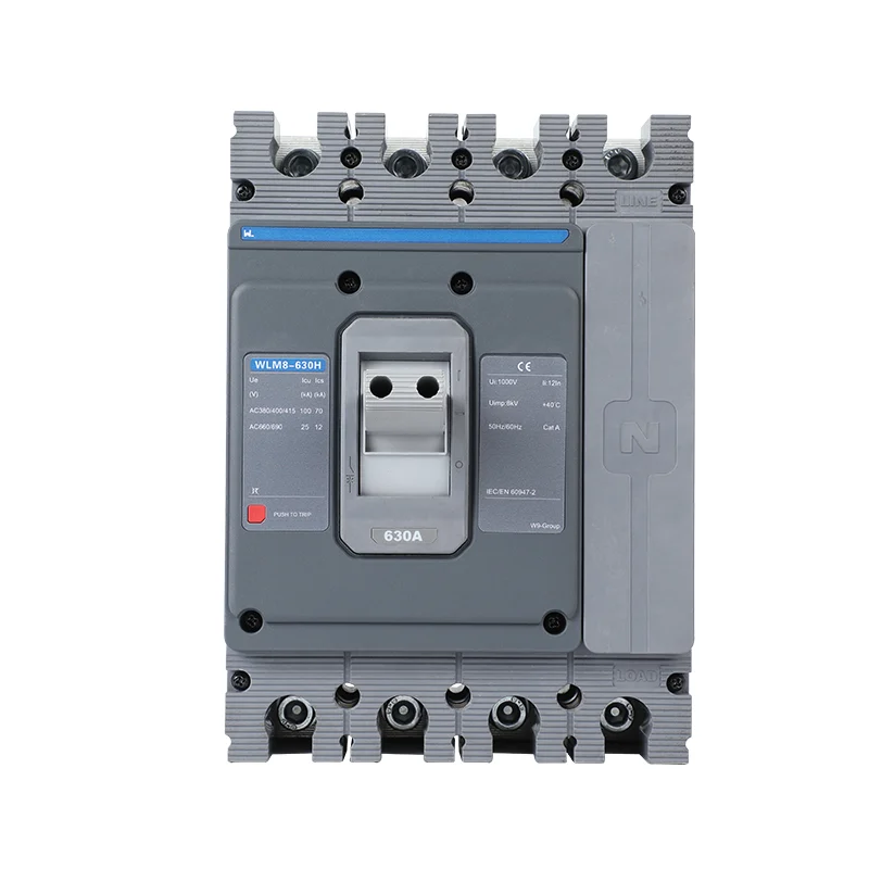
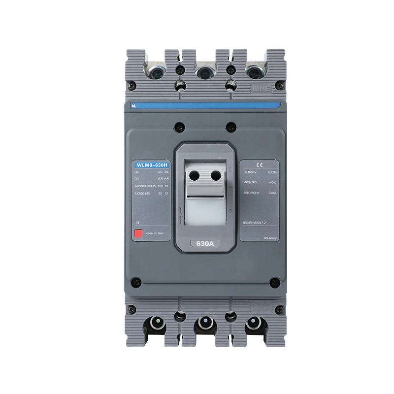
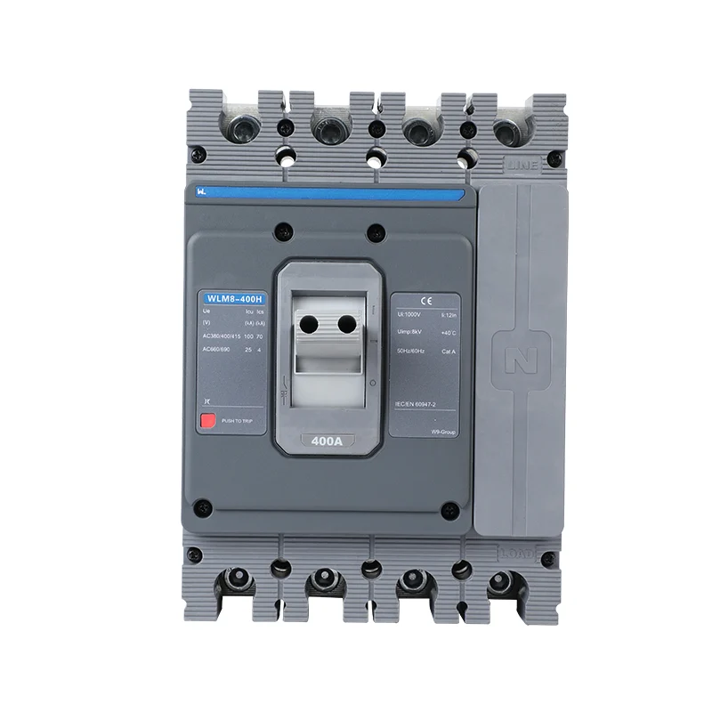
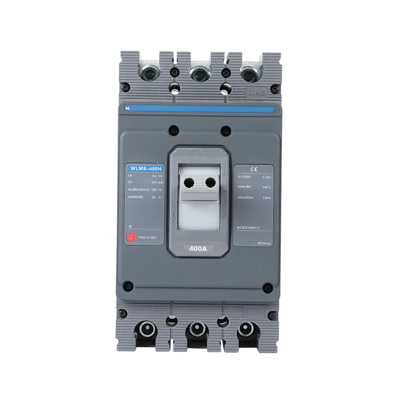





Selección electrónica de MCCB para alimentadores coordinados
A tender may require an electronic MCCB but omit the functions and settings that justified that choice. Suppliers can then return technically different offers under the same description. The price comparison looks straightforward until the engineer discovers that a required delay, ground-fault function or interface is absent from the selected version.
Respuesta rápida: electronic MCCB selection should begin with the feeder’s required protection and coordination, then work back to the complete breaker and release. Compare an electronic option with a thermal-magnetic alternative under the same voltage, load, fault and installation conditions. Require actual curve and tolerance data for any claim of improved response. Carry the selected order code and settings through purchasing, delivery inspection and commissioning. Electronic functionality adds value only when the required functions are supplied, correctly configured and supported during operation.
Start the comparison with the feeder specification
Identify the normal load, starting or energisation duty, conductor design and relevant environmental conditions. Establish the operating voltage and prospective fault current at the installation point. Include the upstream and downstream devices if coordination or continuity of service is required.
Then list the protection functions that the design needs. A general feeder may need overload and instantaneous protection with a suitable curve. Another feeder may require additional delayed or ground-fault overcurrent functions. The required functions should be stated explicitly rather than hidden inside the phrase electronic trip.
El short-circuit rating and coordination guide separates the ability to interrupt a fault from the relationship between protective devices. That distinction is essential when comparing a thermal-magnetic candidate with an electronic one.
Compare trip data under the same conditions
A useful comparison identifies pickup tolerances, time bands, current references and applicable operating conditions. Do not compare a nominal line from one brochure with a tolerance band from another and conclude that one is more accurate. Both candidates need equivalent supporting data.
Check the meaning of each adjustable value. A multiplier based on sensor rating can differ from a multiplier based on another current reference. Record the permitted range and whether other settings change with it. Electronic trip units can also have fixed or override behaviour that remains relevant even when user settings appear flexible.
The same discipline applies to the complete breaker ratings. Compare operating voltage, pole configuration, Icu and Ics where IEC ratings apply. Do not confuse insulation voltage with permissible operating voltage or an overload setting with short-circuit breaking capacity.
| Comparison item | Thermal-magnetic candidate | Electronic candidate | Acceptance question |
|---|---|---|---|
| Overload function | Declared thermal curve and adjustment | Declared long-time function and settings | Does it protect the designed conductor? |
| Starting duty | Magnetic pickup band and thermal history | Applicable pickup, delay and override data | Is legitimate starting compatible? |
| Coordination | Exact device-pair data | Exact device-pair data at selected settings | What selective range is supported? |
| Accuracy claim | Published tolerances and conditions | Published tolerances and conditions | Are the stated values comparable? |
| Service support | Matching manual and field instructions | Matching manual, test method and interfaces | Can the installed version be maintained? |
Use coordination evidence for the exact device pair
Manufacturer coordination data should identify the devices, releases, settings, voltage and relevant fault range. A result for a different frame or trip unit is not automatically transferable. Where the manufacturer declares a selective limit, use that limit and its conditions rather than describing the arrangement as selective without qualification.
Time-current curves help compare overload and delayed operation. In the high-current region, current limitation and device interaction can make tested data important. Simply choosing a larger upstream breaker or adding delay does not prove the required result.
Any delay must also be compatible with equipment withstand and the installation design. Improving continuity in one part of a system cannot be considered independently from protection elsewhere. The engineering study should state the accepted settings and conditions clearly enough that procurement and commissioning can reproduce them.
Consider an illustrative two-stage feeder with one upstream and one downstream breaker. Even this simple arrangement requires identification of both releases and the relevant fault current. Adding a third stage creates another device relationship to check; the existence of an electronic release at one stage does not validate the complete chain.
Compare the cost of a complete working configuration
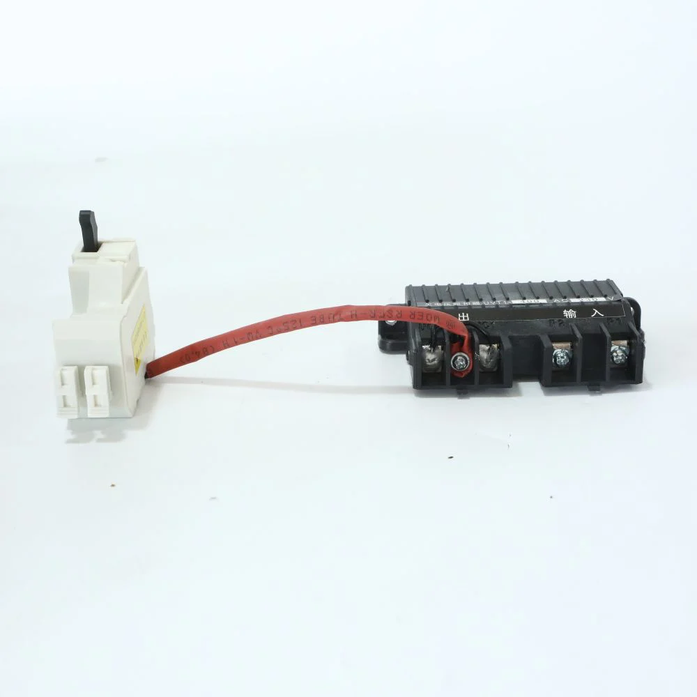
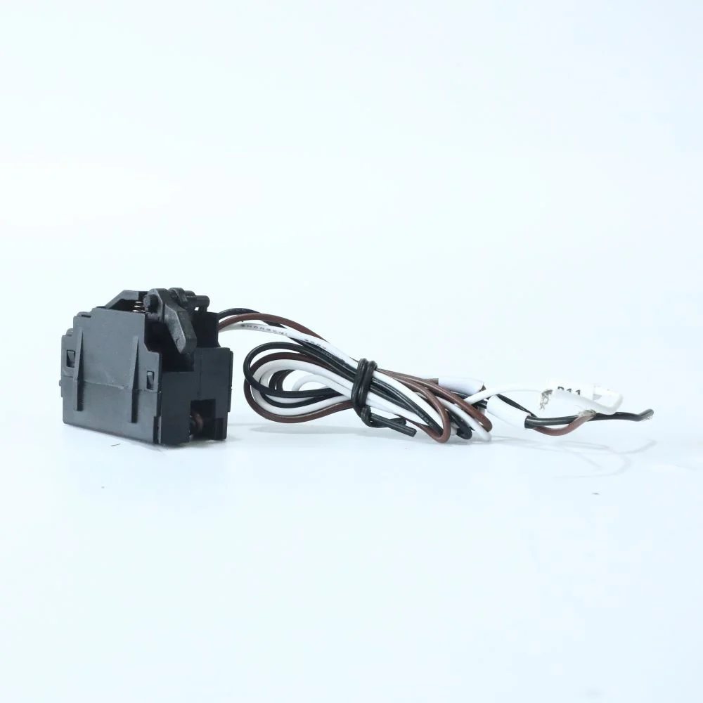
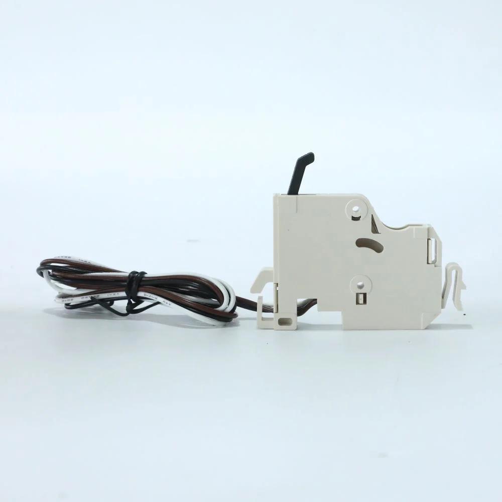
A quoted electronic breaker may need additional equipment for the requested interface, test method or indication. Confirm what is included and what is optional. Communications, metering, a display, auxiliary power and remote operation should each have an explicit requirement where needed.
Include engineering, installation, commissioning, spares and maintenance in the comparison. A thermal-magnetic option may be appropriate where its documented curve meets the duty and the site has straightforward service requirements. An electronic option may be justified by a required function that the simpler release cannot provide. Neither conclusion should be based on a universal ranking.
| Cost or delivery item | What to request | Why it affects the decision |
|---|---|---|
| Base device | Complete order code and release version | Prevents comparison of different configurations |
| Accesorios | Included and optional items separately | Exposes the complete installed cost |
| Engineering | Curves, tolerances and coordination evidence | Supports acceptance of the design |
| Entregue | Settings and applicable test procedure | Connects the delivered device to the study |
| Operation | Manuals, replacement support and change control | Preserves the protection arrangement over time |
For a project-specific cost illustration, use the same labour rates and operating assumptions for both candidates. Show uncertain items as unresolved rather than assigning invented prices. A claimed saving is not established until the proposed configuration and the avoided work are both supported.
Carry electronic MCCB settings through handover
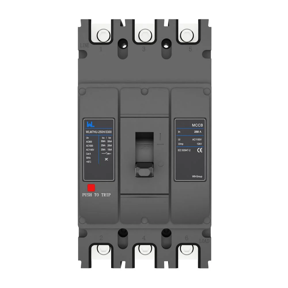
El approved order configuration should identify the frame, release, current, capacity code, poles and accessories. On delivery, compare the actual labels and release functions with that order. A visually similar device with a different suffix may not support the study’s settings.
During commissioning, use the manufacturer’s procedure and the approved setting schedule. Record settings as found and as left, the checks performed and any remaining limitations. Store the information with the feeder documentation so replacement and maintenance teams can retrieve it.
IEC 60947-2:2024 supplies the industrial product-standard context, while installation and assembly requirements remain separate. HSE guidance supports competent work and maintenance based on duty, environment and previous findings. Neither source provides a universal setting for the specific feeder.
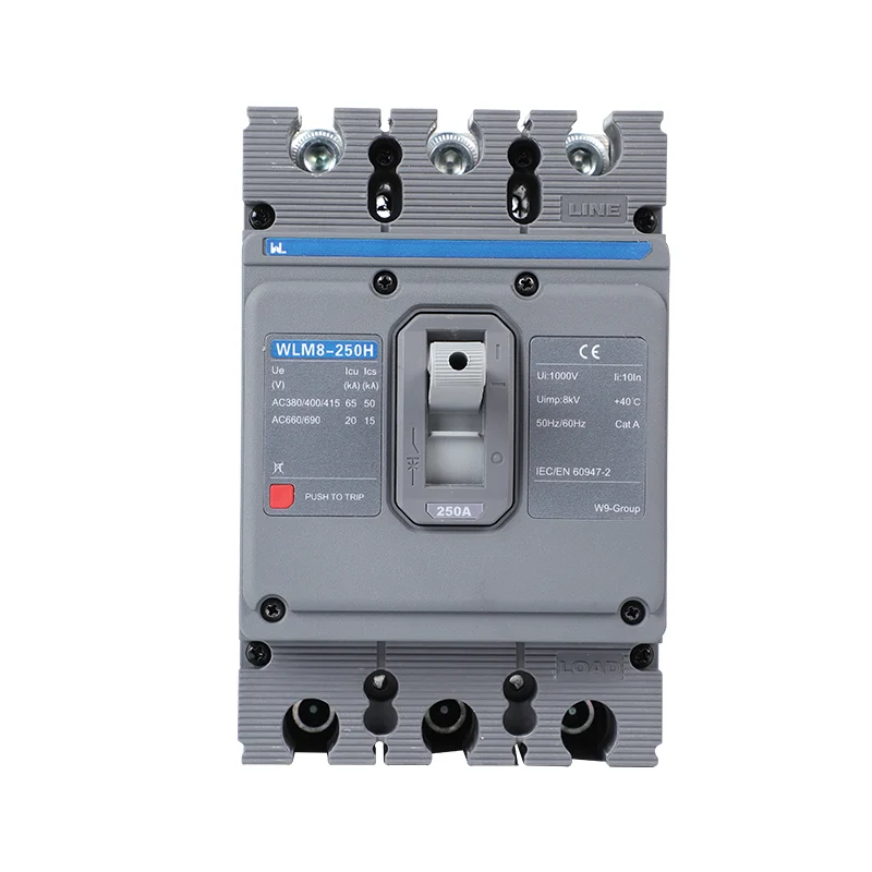
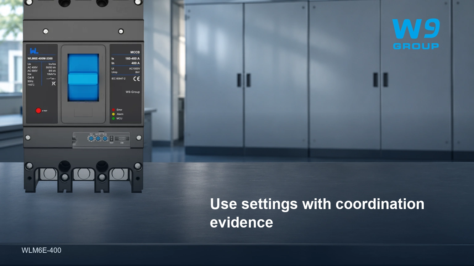
W9 Group’s WLM6E electronic MCCB can be reviewed against these requirements. Request the exact trip-unit function list, voltage-specific ratings, curves and installation documents. Confirm any ground-fault, display or communication option in the quotation.
Keep protection-setting change control in place after handover. A new load, changed supply or replacement device can alter the assumptions behind the original study. Review those changes before adjusting settings; an undocumented dial change should not become the site’s new design by default.

Electronic MCCB Selection Questions
How should a faulty electronic circuit breaker be repaired?
First identify the fault and follow the manufacturer’s service or replacement instructions through competent personnel. Do not improvise internal repairs or bypass protection to restore operation.
Can an electronic circuit-breaker IC replace an MCCB?
No direct substitution follows from that description. An IC is a component within an engineered circuit, while an MCCB is a complete protective device with declared interruption and installation characteristics.
Is an electronic MCCB equivalent to a 24 VDC protector?
Not automatically. Confirm the intended circuit, supply and complete product ratings; the two may serve entirely different application classes.
What is the total cost of an electronic MCCB?
It includes the specified breaker and accessories plus engineering, installation, commissioning and maintenance. Request a configuration-specific quotation rather than comparing unexplained price ranges.
Does the electrical symbol identify every electronic trip function?
No. Use the project drawing convention together with the device and settings schedules. The installed release version must be identifiable beyond a generic breaker symbol.
Can an industrial electronic MCCB be selected for aircraft use?
Only a separate application-specific design and approval assessment could establish suitability. Industrial ratings and an electronic release do not establish aircraft approval.
Referencias
- IEC 60947-2:2024 — circuit-breaker requirements and public scope.
- HSE HSG85 — safe electrical working practices.
- HSE — maintaining electrical equipment safety. Sources checked 2 November 2026.
The selected breaker should be traceable from the engineering study to the installed settings. Compare the W9 Group MCCB range y send the feeder specification for a documented quotation.