








What is the Best Lsig Circuit Breaker for Your Needs?
LSIG is often used to describe long-time, short-time, instantaneous and ground-fault protection in an electronic trip unit. A buyer asking for the best LSIG circuit breaker needs a settings and coordination answer, not an unsupported product ranking.
Quick answer: define each protection function, its adjustable range, delay, tolerances, sensing arrangement and coordination target. Confirm whether the model actually provides L, S, I and G, because not every electronic trip unit includes every function. Ground-fault protection is also not the same as every residual-current protection method.

LSIG Protection Functions
Long-time protection addresses sustained overload; short-time protection supports selective coordination for higher fault levels; instantaneous protection responds quickly to very high current; ground-fault protection detects the configured ground-fault condition. must be mapped to the project protection study and not copied as a generic label.

Settings and selectivity
Pickup and delay settings interact with upstream and downstream breakers. A lower pickup may protect conductors but reduce selectivity; a longer delay may improve coordination but increase withstand requirements. Record the approved setting file, adjustment authority and test method.

Ground-Fault Protection Scope
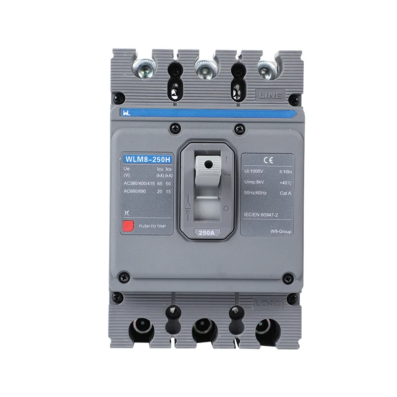
Ground-fault protection can use a sensing and trip arrangement defined by the breaker. It should not be presented as a universal substitute for residual-current protection, insulation monitoring or an earthing design. See MCCB category for the relevant product or guidance.


Define what best means for an LSIG feeder
The best fit is the release whose permitted functions and ranges meet the approved study and can be tested and maintained by the facility. Check the sensor arrangement, neutral treatment and any dependency on auxiliary power. A release with more menu options can still be unsuitable if its minimum pickup or delay does not meet the circuit duty.
| Decision | Evidence |
|---|---|
| Long-time protection | Load, conductor limit and curve |
| Short-time coordination | Downstream curves and withstand |
| Instantaneous response | Inrush and available fault current |
| Ground-fault function | Earthing and sensing diagram |
| Verification | Exact test method and setting record |
Do not assume that every electronic release includes G or that the ground-fault function supplies required additional shock protection. Obtain the exact W9 model and release manual and compare it with the intended protection objective.

LSIG Configuration Evidence
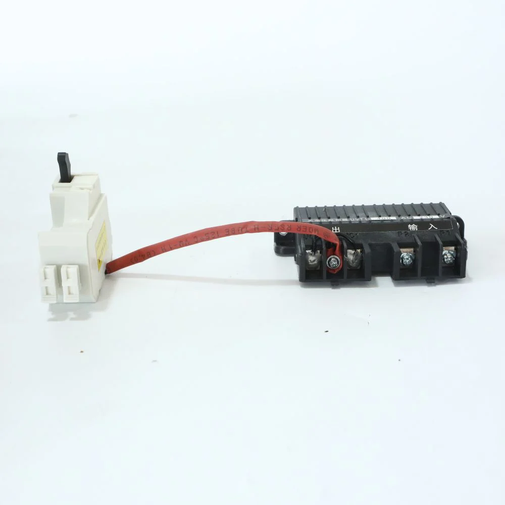
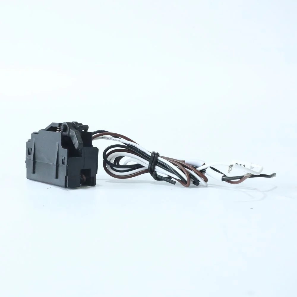
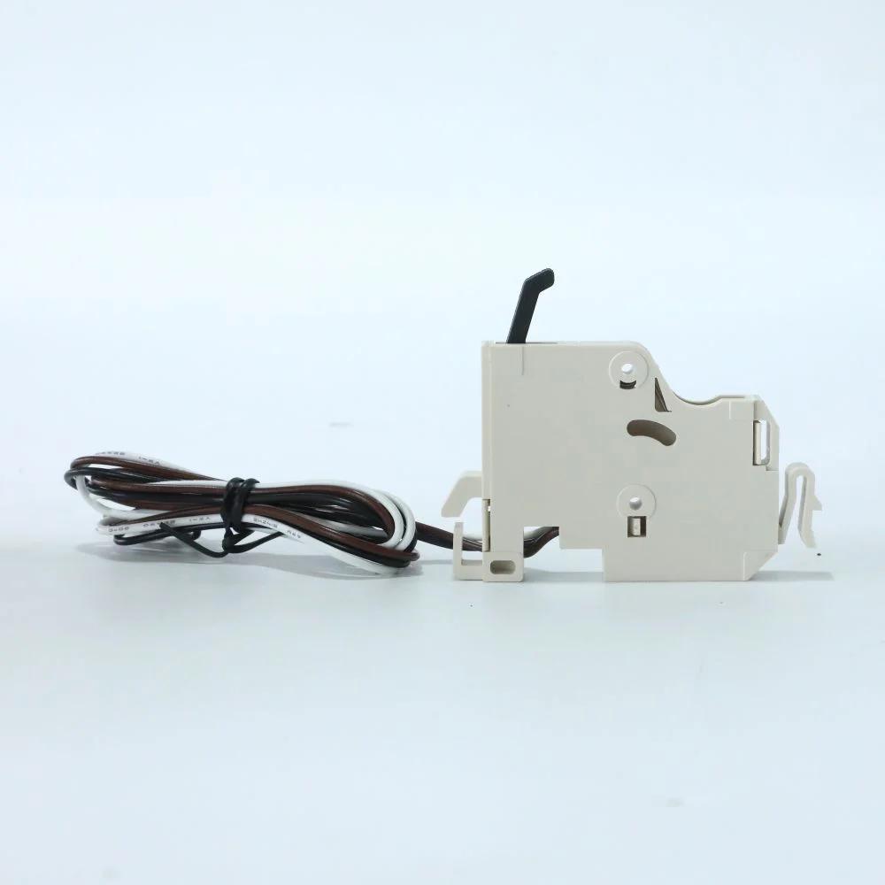
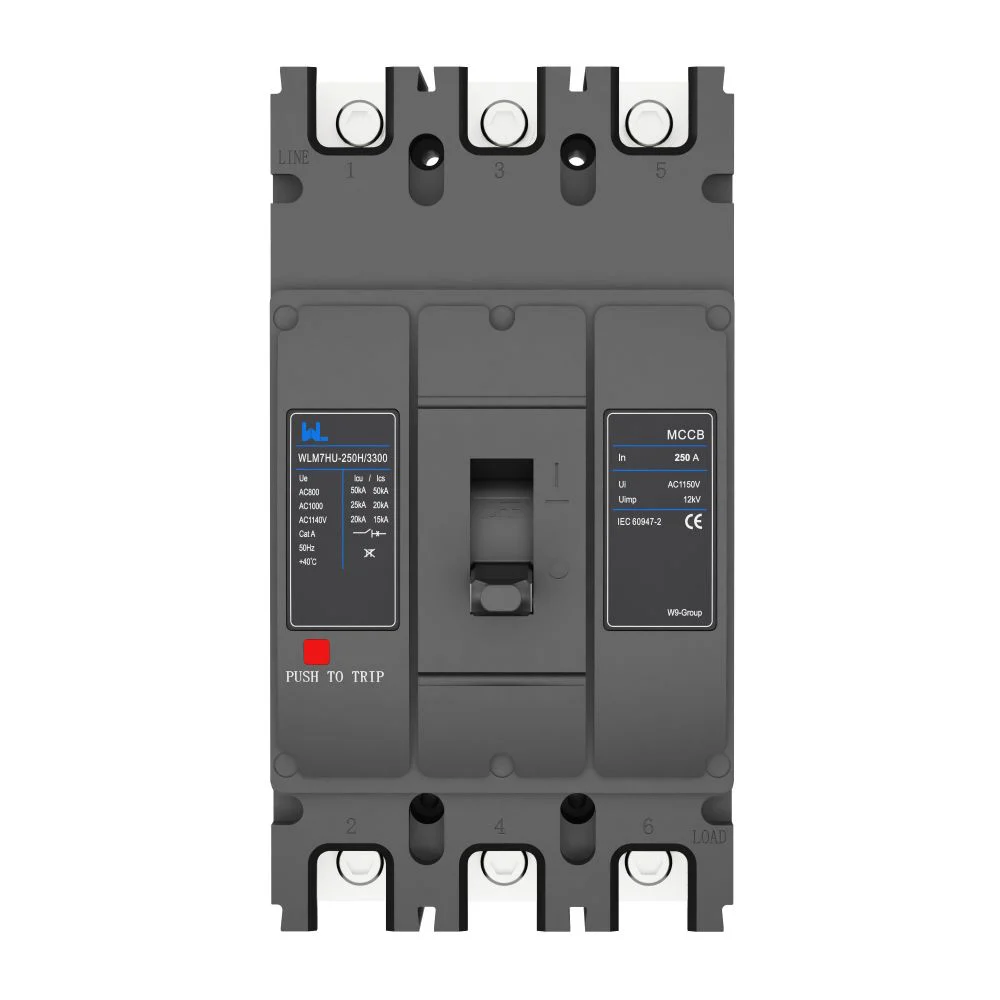
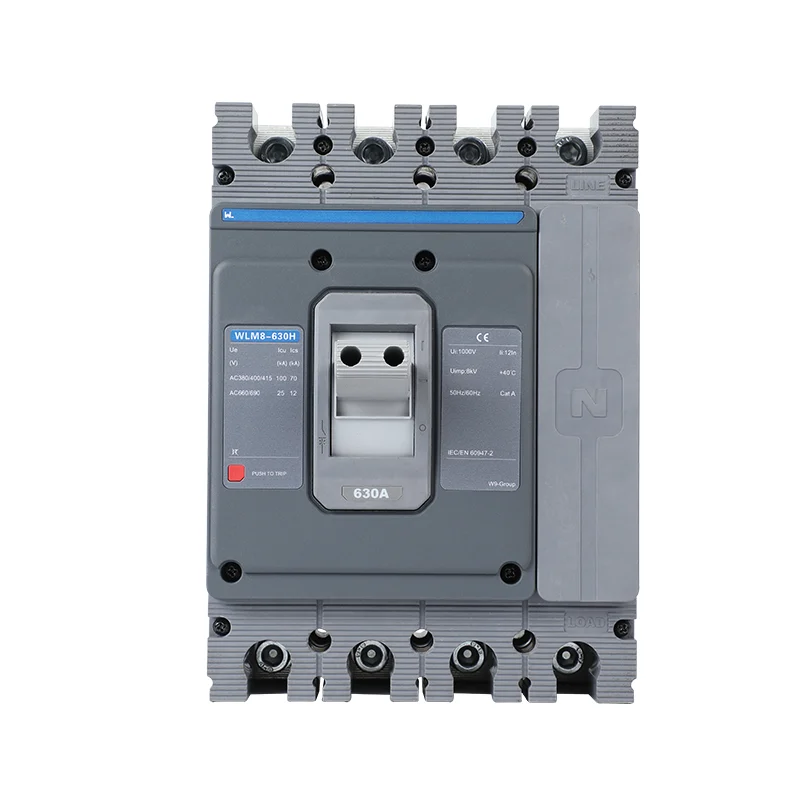
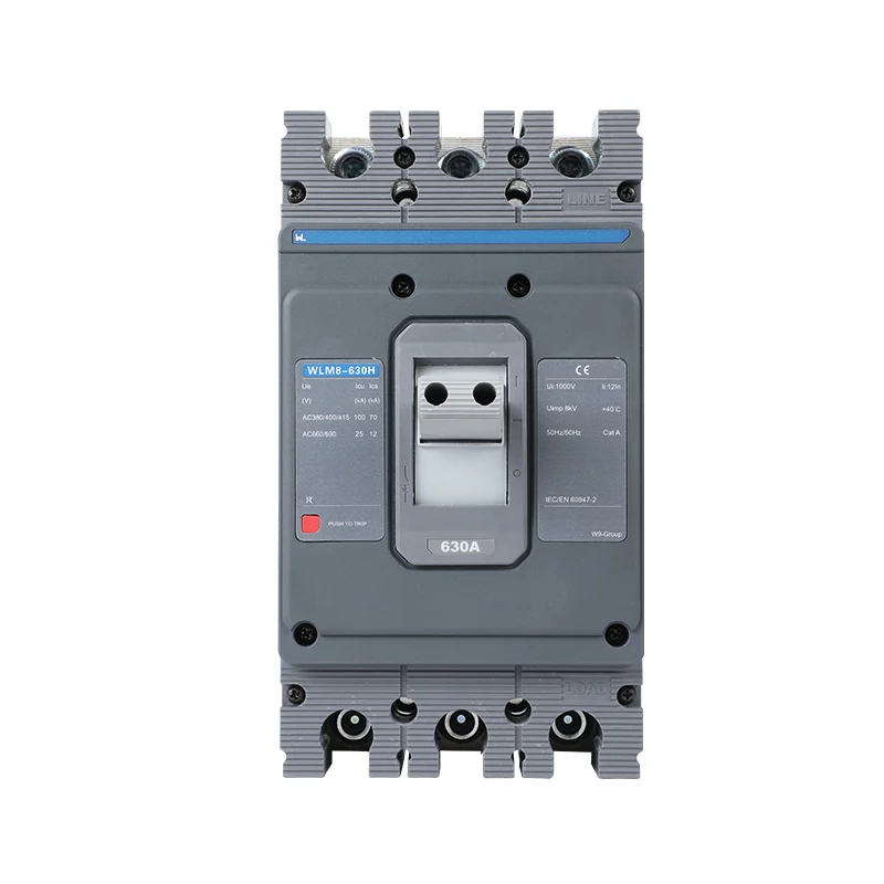
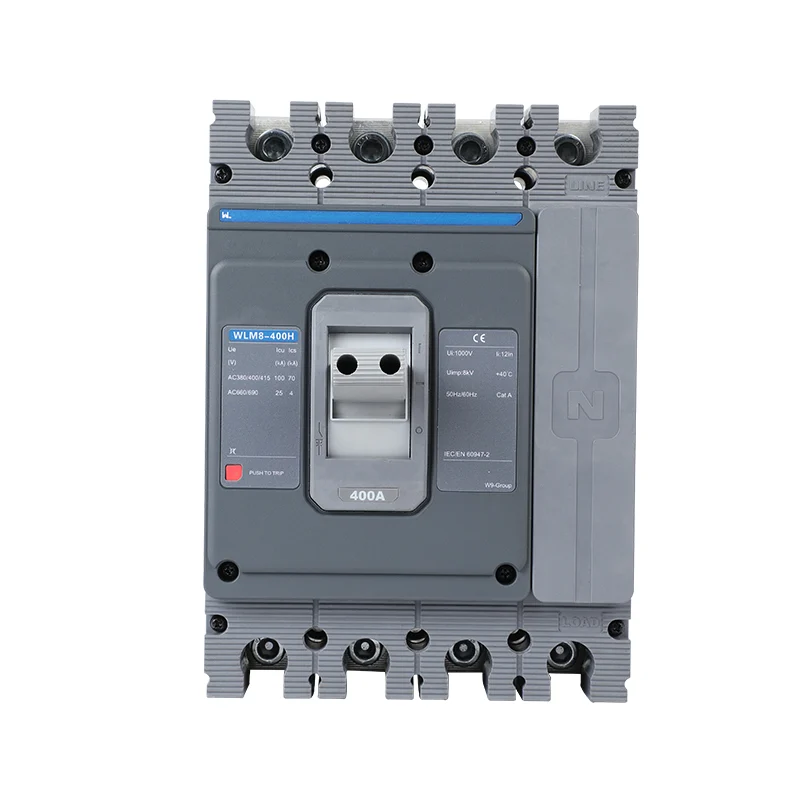
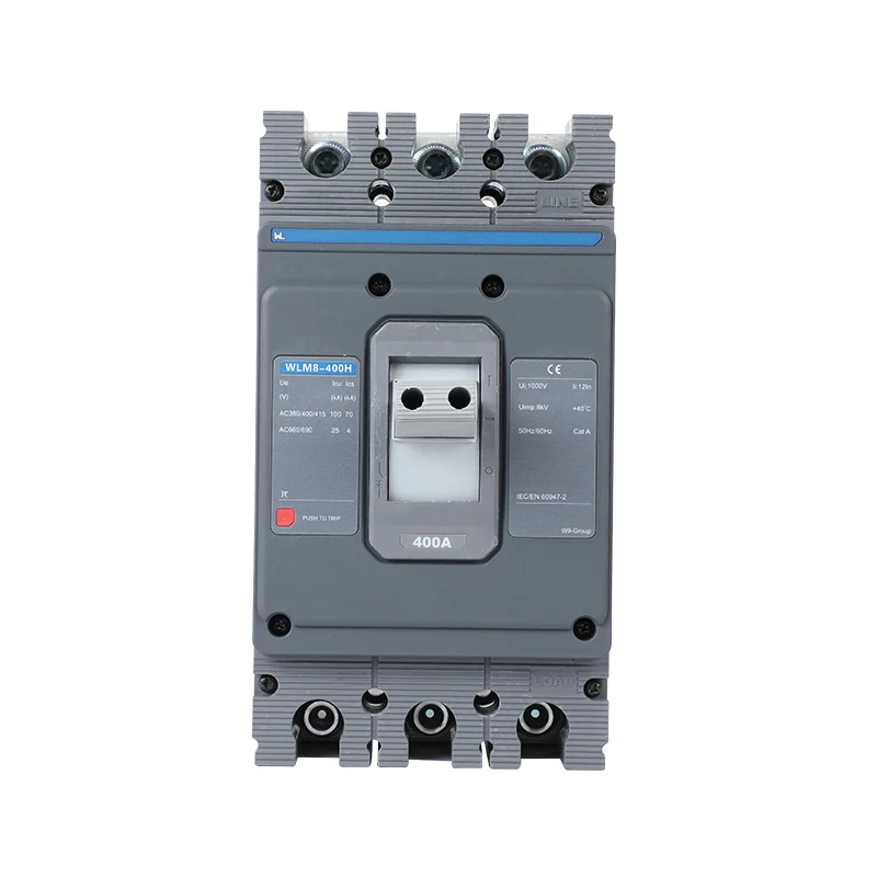
Request the exact trip-unit manual, setting table, sensor arrangement, accessory list and test documentation. W9’s electronic and LCD MCCB ranges should be evaluated by model code and rating; the category page is a starting point, not a blanket specification. See electronic MCCB information for the relevant product or guidance.

Selection checklist
List rated current, voltage, poles, fault current, coordination target, L/S/I/G ranges, ground-fault sensing, auxiliary supply, communications and commissioning records. See request LSIG documentation for the relevant product or guidance.

LSIG Selection Records
At design stage, write the electrical duty and the unresolved assumptions before choosing a catalogue number. State the system voltage, frequency, continuous current, poles, prospective fault current, load profile, ambient conditions and enclosure. This creates a common baseline for every quotation and prevents a supplier from answering a different question with a different configuration.
At quotation stage, ask for a controlled datasheet, model code, outline drawing, terminal arrangement, accessory schedule, setting range, test scope and document revision. Compare like with like: a fixed device, a withdrawable device and a device with communications are different scopes even when the headline current is similar. Record what is included, what is optional and what must be supplied by the panel builder.
At assembly and commissioning stage, confirm the physical identity, mounting, wiring, labels, torque, settings and functional checks against the approved file. If the application is outside the published product scope, stop the release and obtain engineering clarification. This evidence trail is more valuable than a generic “top” label because it lets the next engineer understand why the device was accepted.
| Project stage | Question to close | Evidence to retain |
|---|---|---|
| Design | What duty and fault level must be protected? | Load schedule and protection study |
| Quotation | Which exact model and accessories are included? | Configuration sheet and revision-controlled datasheet |
| Assembly | Does the device fit the verified board arrangement? | Drawings, wiring and assembly records |
| Commissioning | Do settings and functions match the approved design? | Test record, setting file and as-built schedule |
Keep a written boundary around every claim. A product standard is not an installation certificate; a display is not automatically a communication system; an AC rating is not a DC rating; and a supplier category page is not a project-specific approval. Where evidence is missing, turn the statement into a request for a document or a technical confirmation. That habit makes procurement faster because the unanswered items are visible before the purchase order.
Frequently asked questions
Which LSIG breaker is best for my feeder?
Select from the system study, required functions, setting ranges and installation conditions. No universal ranking applies without those inputs.
Does every electronic MCCB include all LSIG functions?
No. Confirm the exact supplied release and optional functions in its manual and order code.
Can longer delay always improve protection?
No. It may support discrimination but increases the period of fault exposure. Review withstand and fault-energy consequences.
What evidence is needed for ground-fault settings?
Use the earthing design, sensing and neutral diagram, required sensitivity and coordination study. Confirm the test procedure for that release.
References and next step
- IEC 60947-2:2024 — circuit-breaker product scope.
- IEC 61439-1:2020 — low-voltage assembly general rules.
- NFPA 70 — U.S. installation-code development and scope.
Use the following public sources to verify scope, then request the exact product documents for your project:
- IEC 60947-2:2024
- W9 MCCB category
- W9 Contact
W9 Group provides low-voltage circuit protection options for OEM, panel-builder and distribution projects; confirm the exact model, ratings, documentation and destination-market requirements before release.
To review the proposed configuration, contact W9 Group with the load schedule, available fault current and destination-market requirements.