































RCBO for EV Chargers: 10kA Differential Circuit Breaker Guide
RCBO for EV Chargers: 10kA Differential Circuit Breaker Guide
When Lena, an EV-installation contractor in Rotterdam, encountered a nuisance trip while energising a new 22 kW charge point, the protective device opened before the first vehicle handshake. The crew replaced the breaker and retested, but the same rapid trip appeared. A review of the charger’s residual-current behaviour, a shared neutral in the distribution board and the upstream RCD arrangement reversed the diagnosis: the product was not “bad”; the protection specification and wiring coordination were incomplete.
Summary: An RCBO for EV charger circuits must cover both overcurrent and residual current, with a breaking capacity suitable for the calculated prospective fault current. IEC 62955 addresses residual direct current (6 mA) detection for mode 3 EV charging, while IEC 61851-1 and IEC 60364-7-722 define EV-system and installation provisions. A 10kA RCBO is a fault-interruption rating, not a guarantee that every EV installation needs 10 kA. Confirm the charger’s built-in 6 mA DC monitor, choose Type A, Type B or another permitted arrangement accordingly, and coordinate the downstream device with upstream protection before energising.
Unlike a general socket load, EV supply equipment (EVSE) contains rectifiers, switching electronics and filters. Charging current is substantial and continuous; faults can include AC, pulsating DC or smooth DC. A differential circuit breaker (the residual-current part of an RCBO) compares current in monitored conductors and trips on imbalance, while its overcurrent release protects against overload and short circuit.
Why EV charging needs deliberate residual-current protection
Charging electronics can produce a smooth DC residual current that may saturate the sensing core of a conventional Type A device. IEC 62955 specifies requirements for residual direct current detecting devices (RDC-DDs) used with mode 3 charging equipment; many EVSE designs use 6 mA DC detection so that an upstream 30 mA Type A RCD can remain effective. The installer must verify what the particular EVSE actually provides rather than infer it from a marketing name.
Type A RCBOs detect AC sinusoidal and pulsating DC residual currents. Type B devices add sensitivity to smooth DC and mixed-frequency residual current and are often considered where 6 mA DC detection is absent or the equipment manufacturer requires it. Type F may be permitted for certain single-phase variable-speed loads, but it is not a universal EV solution. Type AC responds only to sinusoidal AC and is generally unsuitable where EVSE electronics can generate pulsating or smooth DC. This waveform choice is central to EV charging protection; follow charger instructions and local wiring rules.
How to read a 10 kA RCBO specification
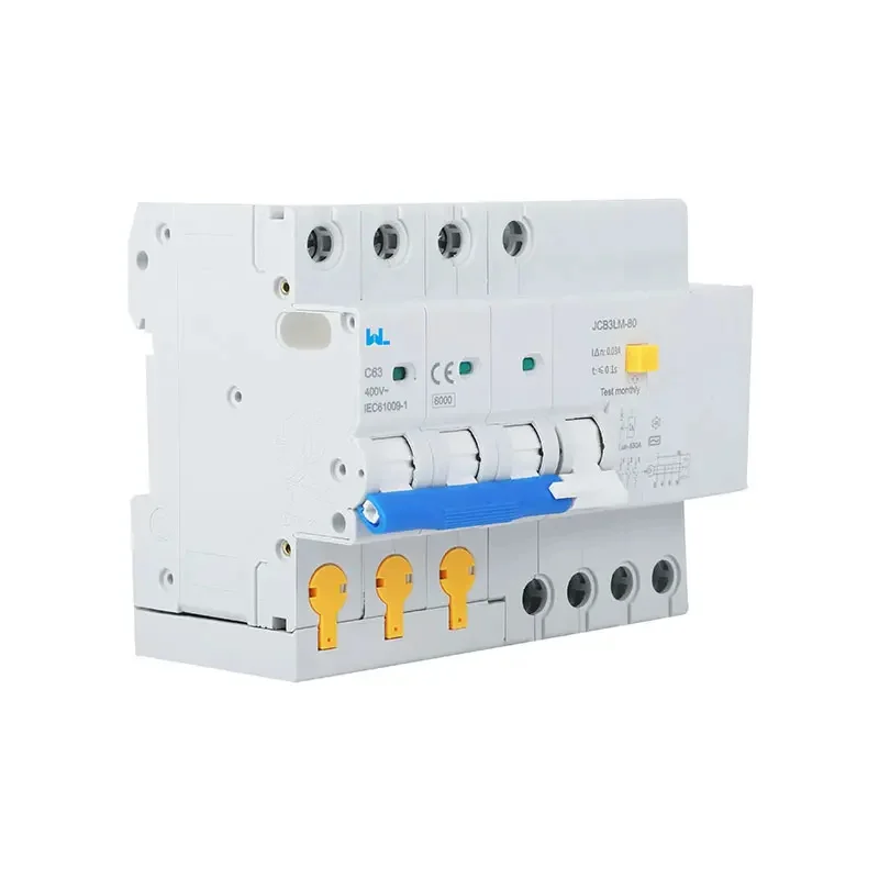
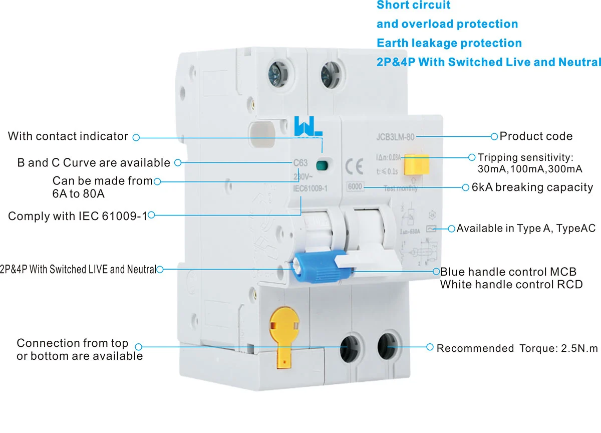
“10 kA” normally denotes rated short-circuit capacity (Icn or an equivalent designation). It describes fault current interrupt capability under specified tests; it does not describe charging power, continuous current or residual sensitivity. The W9 listing for JC3LE-EV identifies an electromagnetic, two-pole EV RCBO, a 10 kA claim and current options up to 63 A. Treat it as orientation and obtain exact datasheet, marking and conformity evidence for the supplied JCR2/JC3LE configuration.
Selection starts with design current (Ib), cable capacity (Iz), protective rating (In) and installation derating. EV charging is a long-duration load, so ambient temperature, grouped circuits, enclosure ventilation and terminal rise matter. Illustrative only: at 230 V and 32 A, apparent input power is 230 × 32 = 7.36 kVA before power factor, efficiency, diversity or site limits. Verify the EVSE nameplate, cable ampacity, voltage drop and local continuous-load rule.
| Arrangement | Detects | When it may fit | Verification point |
|---|---|---|---|
| Type A RCBO + EVSE 6 mA RDC-DD | AC and pulsating DC at the RCBO; EVSE monitors smooth DC | Common mode 3 approach where the charger manufacturer specifies it | Confirm RDC-DD compliance, test method and alarm/trip behaviour |
| Type B RCBO/RCD | AC, pulsating DC and smooth DC, subject to device scope | EVSE lacks 6 mA DC detection or requires broad waveform coverage | Check manufacturer instructions, cost, dimensions and selectivity |
| Type AC RCBO | Sinusoidal AC only | Only where a competent designer confirms no DC or pulsating component | Do not use by default for power-electronic EVSE |
Coordinate upstream and downstream protection
Place an RCBO for EV charger circuits downstream of the distribution-board main protection and check discrimination. Compare short-circuit ratings with prospective fault current at the charger, not merely at the service entrance. For residual protection, compare trip sensitivity, delay, waveform capability and the EVSE’s 6 mA DC behaviour. An upstream selective RCD helps only when manufacturer time-current data supports it; this is an EV charging protection check.
All current-carrying conductors that belong to the circuit must pass through the sensing path. A shared or borrowed neutral, neutral-to-earth contact downstream, or a line conductor bypassing the RCBO can cause nuisance trips or defeat protection. A two-pole device is normally used for a single-phase line-and-neutral circuit; three-phase EVSE requires a pole arrangement and neutral treatment specified by the equipment and installation design. Keep the EV circuit physically and electrically segregated from unrelated neutrals.
Thermal loading, installation and commissioning
EV charging can run for many hours, so verify cable ampacity after ambient, grouping, conduit and termination corrections. Tighten terminals to instructions, use the specified conductor cross-section and provide EVSE strain relief. Mount on the prescribed DIN rail, maintain clearances and label the circuit. Confirm dimensions, torque and environmental limits in the current technical file.
Commissioning combines visual inspection with instrument tests: protective-conductor continuity, polarity, insulation resistance (with EVSE electronics isolated as instructed), loop or prospective-fault values, residual operating current and trip time. Use a tester supporting the selected Type A or Type B waveform and the EVSE’s 6 mA DC function; the RCBO test button alone is insufficient. Record instrument, mode, values and remedial actions, then re-test after changes.
Selection checklist for installers and OEM buyers
- Document the EVSE: Record mode, phase arrangement, maximum current, built-in 6 mA DC detection and the manufacturer’s required RCD type.
- Calculate fault and load values: Establish design current, cable ampacity after derating, voltage drop and prospective short-circuit current at the RCBO terminals.
- Choose waveform and sensitivity: Specify Type A or Type B (and the permitted residual threshold/time characteristic) from the equipment and risk assessment; do not substitute Type AC by habit. Document the EV charging protection rationale.
- Check coordination: Confirm upstream/downstream selectivity, neutral routing, pole count, busbar compatibility and enclosure thermal capacity.
- Request evidence: Obtain the declaration, test reports, installation diagram, marking, terminal torque and destination-market approvals for the exact configuration.
- Plan service: Label the circuit, provide safe test access and schedule periodic inspection based on the manufacturer, local rules and site risk.
Zhejiang W9 Group Technology Co., Ltd., founded in 2020, supplies low-voltage protection products and offers OEM/ODM and testing support. Ask W9 to confirm the exact JCR2/JC3LE-EV model, 10 kA test basis and destination-market documentation.
| Stage | Question | Evidence to retain |
|---|---|---|
| Design | What are Ib, Iz, fault current and EVSE residual-current characteristics? | Load schedule, cable calculation and charger manual |
| Procurement | Does the exact RCBO carry the required marking and breaking-capacity rating? | Datasheet, declaration and coordination tables |
| Installation | Are poles, neutrals, torque, ventilation and segregation correct? | As-built diagram and torque/inspection record |
| Handover | Were residual, insulation and fault-loop tests completed with suitable instruments? | Signed commissioning results and maintenance interval |
Standards and market scope
IEC 62955 covers RDC-DDs for mode 3 EV charging. IEC 61851-1 sets conductive charging requirements; IEC 60364-7-722 addresses low-voltage installations supplying EVs. IEC 61009-1 is the RCBO product standard for household and similar applications. Their scopes differ, and citing one does not certify a complete installation.
For North American projects, UL 2231-1/-2 address personnel-protection systems for EV supply circuits, while UL 943 covers GFCI devices. Applicability depends on construction, supply system and listing route. State the destination market early; a similar 10kA RCBO may not be acceptable in a listed assembly.
Frequently asked questions
How do you choose an RCBO for EV charger circuits?
There is no universal answer. Type A with verified 6 mA DC detection in the EVSE is a common arrangement; Type B may be required when that function is absent or specified by the charger maker. Confirm IEC 62955-related evidence and local rules before ordering.
Is a 10kA RCBO necessary for every EV installation?
No. The 10 kA value must meet or exceed the prospective fault current at the installation point, with any permitted backup or cascading arrangement considered. A higher label does not compensate for incorrect wiring, thermal derating or poor selectivity.
Can a Type A RCBO detect the DC leakage from an EV?
Type A detects pulsating DC and AC, but smooth DC can saturate some residual-current sensors. Use a compliant 6 mA DC RDC-DD in the EVSE or select the broader device type required by the equipment documentation; never infer capability from the word “differential.”
Why does an RCBO for EV charger circuits trip after several minutes?
Delayed trips can result from cumulative leakage, thermal loading, a neutral fault, moisture or an EVSE waveform outside the device capability. Measure residual current and temperature under load, inspect connections and follow the charger’s diagnostic procedure before replacing the RCBO.
What tests should be completed before handover?
Perform visual, protective-conductor, polarity, insulation (as permitted), loop/prospective-fault, residual trip-current and trip-time tests, plus the EVSE’s 6 mA DC function where provided. Record results and repeat after alterations.
For background, see what an RCBO does and how RCBOs enhance electrical safety. Review the W9 EV RCBO listing and confirm its live datasheet.
References
- International Electrotechnical Commission: IEC 62955, IEC 61851-1, IEC 60364-7-722 and IEC 61009-1.
- UL Solutions: UL 2231-1, UL 2231-2 and UL 943 scope information.
- National Fire Protection Association: NFPA 70 context for EV supply equipment and overcurrent protection.
The dependable rule is simple: match the EVSE waveform, conductor capacity, fault level and test evidence as one protection system. That is the foundation of defensible EV charging protection. For an RCBO for EV charger, review W9’s product range and contact the team with circuit data and destination-market requirements.