































RCCB Wiring, Test-Button Checks, and Commissioning Guide
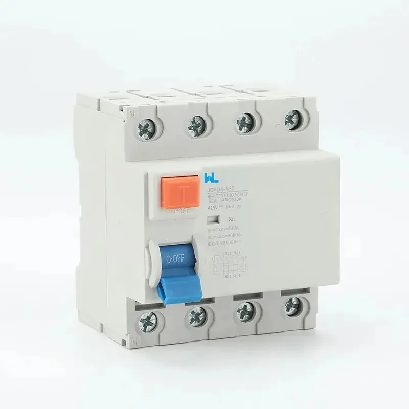
An RCCB that trips during commissioning can indicate a wiring error, a genuine insulation fault, mixed neutrals, cumulative leakage, or a device that is not coordinated with the rest of the protection system. For a panel builder or procurement engineer, the priority is to preserve the evidence and establish the protection boundary before anyone repeatedly resets the device. This guide explains how to review RCCB wiring, use the RCCB test button as a functional check, and assemble a defensible commissioning record without turning a general article into a site-specific wiring instruction.
خلاصه: An RCCB compares the current leaving through the protected live conductors with the current returning through the sensing path. Correct RCCB connection therefore depends on the selected device’s terminal diagram, pole arrangement, neutral segregation, upstream overcurrent protection, and the installation rules for the destination. The front-panel test button checks the device’s internal test circuit and trip mechanism; it does not prove insulation resistance, earth continuity, polarity, selectivity, or correct downstream wiring. Commissioning should follow the approved drawings and manufacturer instructions, be carried out by qualified personnel using an approved isolation procedure, and stop when a trip cause or wiring condition is not understood.
RCCB Wiring Verification
Begin with the single-line diagram, the exact product data sheet, and the installation instructions for the ordered configuration. An RCCB is generally a residual-current circuit-breaker without integral overcurrent protection under IEC 61008-1. The overcurrent device, short-circuit coordination, earthing arrangement, and downstream conductors therefore remain part of the design rather than optional accessories.
The sensing path is the central question. Every live conductor belonging to the protected circuit must be included as specified by the product documentation. A neutral borrowed from another circuit, a neutral-to-earth connection downstream, or a conductor routed outside the sensing arrangement can cause nuisance tripping or undermine the intended protection boundary. Do not infer terminals, line/load orientation, neutral treatment, or a two-pole/three-phase arrangement from a different model or a generic internet diagram.
| Review item | What to confirm | Evidence to retain |
|---|---|---|
| Device identity | Exact model, product category, pole count, rated current, residual-current type, and declared operating characteristics. | Controlled data sheet, order code, nameplate photograph, and revision/date. |
| Conductor path | All relevant live conductors pass through the specified sensing path; line and load sides follow the manufacturer’s diagram. | Approved schematic, panel wiring record, and visual inspection result with the circuit isolated. |
| Neutral management | Protected neutrals are segregated from other circuits and no unapproved downstream neutral-to-earth bond exists. | Neutral schedule, terminal identification, and inspection/test record. |
| Overcurrent coordination | An MCB, fuse, MCCB, or other suitable device protects the RCCB and downstream wiring where the RCCB does not provide integral overcurrent protection. | Coordination statement, protective-device schedule, and fault-duty/design record. |
| System application | Single-phase, three-phase, or four-wire use matches the selected pole arrangement and local installation rules. | One-line diagram, load schedule, and design approval. |
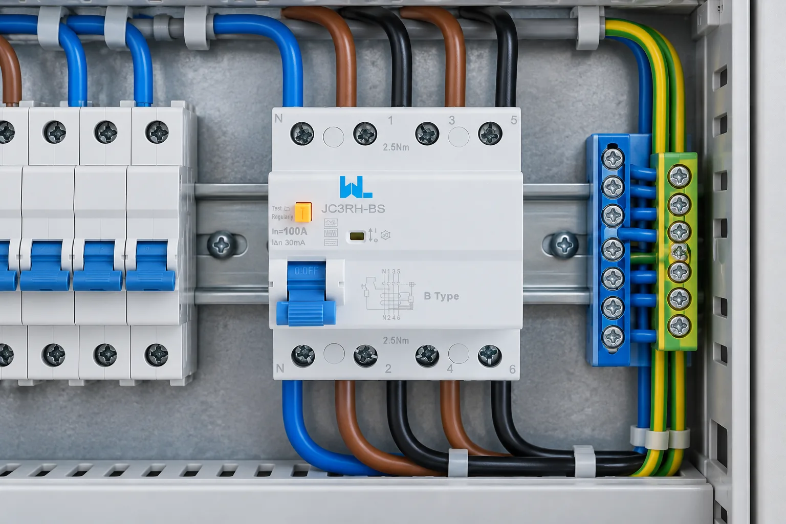
A two-pole RCCB is commonly evaluated for a single-phase line-and-neutral circuit when both conductors must be switched or isolated together. A three-phase or four-wire application may require a different pole arrangement and a documented neutral treatment. These are selection questions, not universal pinouts. The final RCCB connection must be taken from the exact device drawing and approved project design.
RCCB Test-Button Checks
The test button is a controlled functional check: it creates an internal test condition intended to make the RCCB trip. Before pressing it, confirm that the interruption is authorised, downstream equipment can safely lose supply, and the person performing the check is following the site’s isolation, access, and restoration procedure. Record the device state before the test and the time, result, and reset status afterwards.
A successful test-button operation shows that the internal test circuit and trip mechanism responded under the conditions of the test. It does not establish that every downstream conductor is routed correctly, that insulation is sound, that protective earth continuity is adequate, that the residual-current type suits electronic loads, or that the device will meet the project’s disconnection and selectivity requirements. If the button does not trip the device, do not compensate by repeated pressing or by changing wiring at random. Remove the circuit from service and escalate for the manufacturer-approved diagnostic path.
| Record field | Commissioning note |
|---|---|
| Precondition | Device identity, circuit reference, supply status, load consequence, and authorised test window. |
| Action | Operate the front-panel test control only as described in the device instructions and site procedure. |
| Expected observation | RCCB trips and indicates the open/tripped state appropriate to the model. |
| Restoration | Reset only after confirming the circuit is safe to re-energise and the test result is logged. |
| Boundary | Test-button success is not proof of insulation resistance, polarity, earth continuity, leakage level, or coordination. |
RCCB Commissioning Fault Diagnosis
Use the following matrix to keep fault-finding proportional to the available evidence. Measurements, isolation, and any access to live parts belong to competent personnel using the applicable local procedure and approved instruments. A general article cannot specify a safe test voltage, terminal sequence, or reset permission for every installation.
| Symptom | Check | Action | Stop and escalate when |
|---|---|---|---|
| Test button does not trip | Confirm the device is energised as required by its instructions, correctly identified, and not visibly damaged. | Keep the circuit out of service and request the approved diagnostic or replacement review. | The supply condition, device status, or cause of non-operation cannot be verified. |
| Trips immediately after energisation | Review the approved diagram for mixed neutrals, downstream neutral-to-earth contact, conductor routing, and load leakage. | Isolate under site procedure, document the trip indication, and test the suspected circuit through the authorised commissioning plan. | A fault remains energised, insulation damage is suspected, or repeated reset would expose people or equipment. |
| Trips only when one load starts | Check the load manufacturer’s leakage information, switching sequence, filters, drives, and cumulative leakage. | Compare the selected RCCB type and coordination with the design record; do not increase the residual-current setting without engineering approval. | The load waveform or protection requirement is unknown, or a setting change would alter the approved protection philosophy. |
| Trips after several circuits are connected | Check circuit grouping, neutral segregation, cumulative leakage, and the sequence of reconnection. | Reconnect only through the documented commissioning plan and record each circuit’s result. | The fault cannot be isolated to a circuit or the panel drawing no longer matches the installation. |
| Will not reset after a trip | Confirm the handle position, supply condition, downstream fault status, and any mechanical interlock or accessory indication. | Leave the circuit isolated while a qualified person follows the product troubleshooting instructions. | There is heat, smell, visible damage, an unexplained control signal, or a high-energy fault history. |
RCCB Commissioning and Handover Requirements
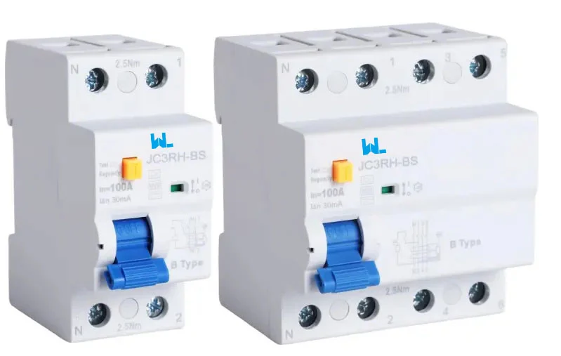
IEC 61008-1 is the principal product-standard reference for residual-current circuit-breakers without integral overcurrent protection. It does not replace the installation standard, local electrical code, authority requirements, switchboard assembly requirements, or the project protection study. If the device is an RCBO with integral overcurrent protection, the relevant product category and standard must be checked instead. The exact edition and destination-market requirements should be confirmed before procurement or approval.
Separate product evidence from installation evidence. A data sheet or declaration may identify the product category; it does not prove that the installed wiring, earthing, clearances, settings, or coordination are correct. Keep the final record limited to checks actually performed and results supported by approved instruments and procedures.
| Evidence group | Minimum record | Owner or reviewer |
|---|---|---|
| Design and identity | Approved one-line diagram, circuit reference, exact RCCB model/order code, pole arrangement, and revision-controlled data sheet. | Design engineer and panel builder. |
| Wiring verification | Signed inspection of conductor path, neutral segregation, protective-device arrangement, labels, terminals, and enclosure condition. | Qualified installer or commissioning engineer. |
| Functional check | RCCB test-button result, trip/reset observation, date, instrument or procedure reference, and any abnormal observation. | Commissioning engineer. |
| Protection verification | Applicable insulation, continuity, polarity, leakage, or disconnection checks required by the project and local rules, with actual results. | Test engineer or authorised inspector. |
| Handover pack | Final drawings, instructions, settings or coordination record, defect closure, operating limitations, and maintenance/test interval assigned by the responsible authority. | Project manager, owner, or authority having jurisdiction. |
- Define the duty: record system voltage and frequency, circuit type, earthing arrangement, load behaviour, expected leakage, ambient conditions, and destination-market rules.
- Specify the RCCB: confirm the exact product category, poles, rated current, residual-current type and operating characteristics, terminals, and environmental limitations from the current technical file.
- Draw the boundary: show the live conductors in the sensing path, neutral segregation, associated overcurrent device, upstream residual-current devices, and downstream circuits.
- Plan commissioning: define who may isolate, inspect, test, reset, and approve restoration; include the test-button check and the additional verification required by local rules.
- Close the evidence: record deviations, unresolved trips, instrument references, drawing revisions, operating limitations, and the person accepting handover.
W9 Group supplies low-voltage circuit-protection options for OEM, panel-builder, and distribution projects. Review the W9 Group RCCB category for the relevant product family, then request the exact model documents for the project. For application questions, use حمایت فنی or provide the approved drawing and duty information through the W9 Group contact page. The existing RCCB electrical-safety overview is useful for background context; it does not replace the selected device’s instructions or local installation rules.
سوالات متداول
What should an RCCB wiring diagram show?
It should show the supply and load sides, every relevant live conductor in the sensing path, neutral segregation, the associated overcurrent protective device, earthing arrangement, pole configuration, and the downstream circuits inside the protection boundary. The terminal arrangement and any line/load restrictions must come from the exact manufacturer’s diagram, not a generic illustration.
What is the difference between an MCCB and an RCCB?
An MCCB is primarily selected for overload and short-circuit protection. An RCCB responds to residual-current imbalance and normally requires coordinated overcurrent protection. They can be used together, while an RCBO may combine residual-current and overcurrent functions in one device where the design calls for it.
What is the difference between RCD and RCCB?
RCD is often used as a broad term for residual-current devices. RCCB identifies a particular residual-current circuit-breaker category, commonly without integral overcurrent protection. Terminology varies by market, so the applicable product standard, declared function, pole arrangement, and data sheet should control the specification.
How much does an RCCB cost, and what is the total cost?
There is no responsible universal price. Total cost depends on the exact product, poles, residual-current type, upstream protection, panel changes, wiring and testing, documentation, logistics, and the cost of investigating nuisance trips. Compare configuration-specific quotations and installed scope rather than a nominal unit price.
When is a 2-pole RCCB used?
A 2-pole RCCB is commonly evaluated for a single-phase line-and-neutral circuit when both conductors must be switched or isolated together. The correct use still depends on the device design, neutral rules, upstream protection, and local installation requirements. Confirm the exact connection diagram before installation.
Can an RCCB be used on a three-phase circuit?
It may be suitable when the selected RCCB has the required pole arrangement and the design includes all relevant live conductors, neutral treatment, overcurrent coordination, and residual-current characteristics for the load. Three-phase application is not established by the label alone; obtain the manufacturer’s diagram and project approval.
The commissioning objective is not simply to make an RCCB reset. It is to show that the selected device, sensing path, complementary overcurrent protection, test-button result, installation checks, and handover documents all describe the same protected circuit. When the evidence conflicts, leave the circuit in the safe state and resolve the design or installation issue before energisation.